|
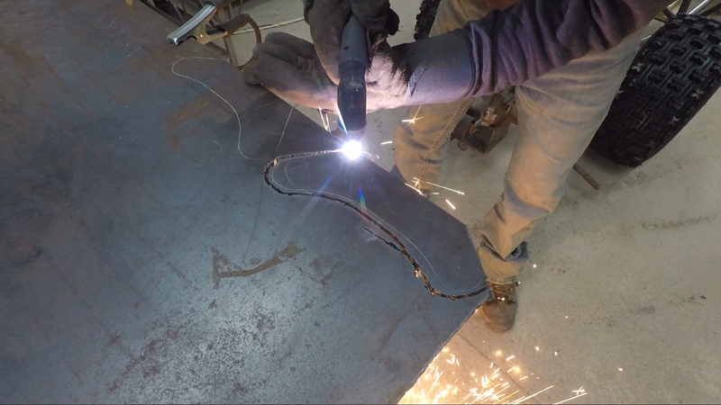
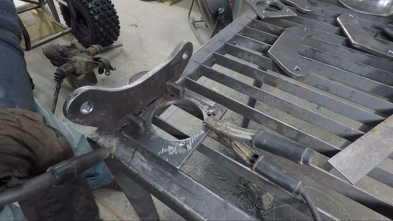
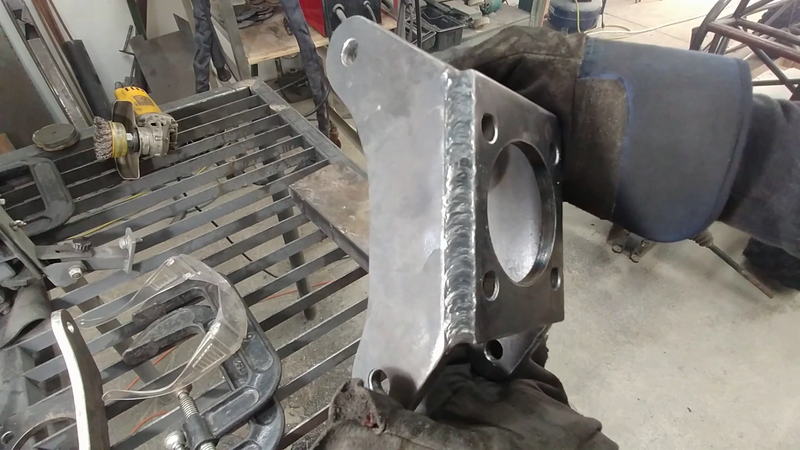
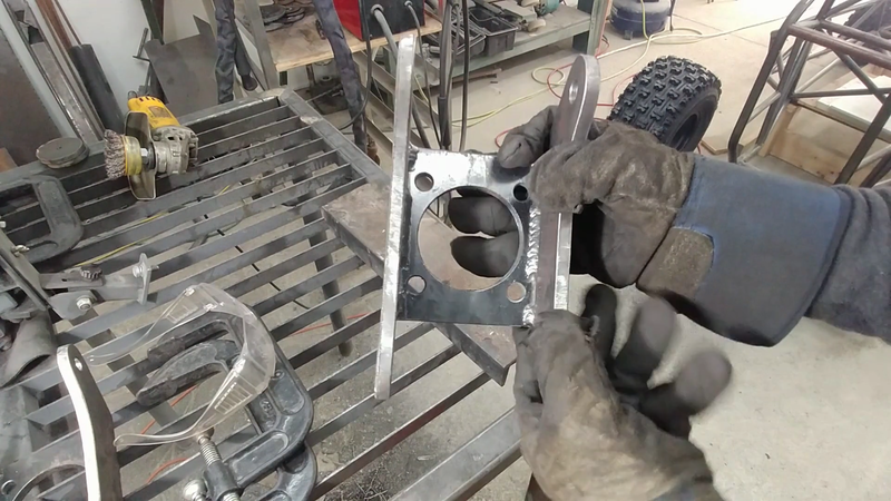
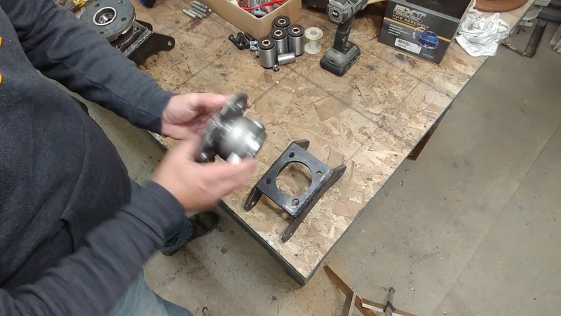
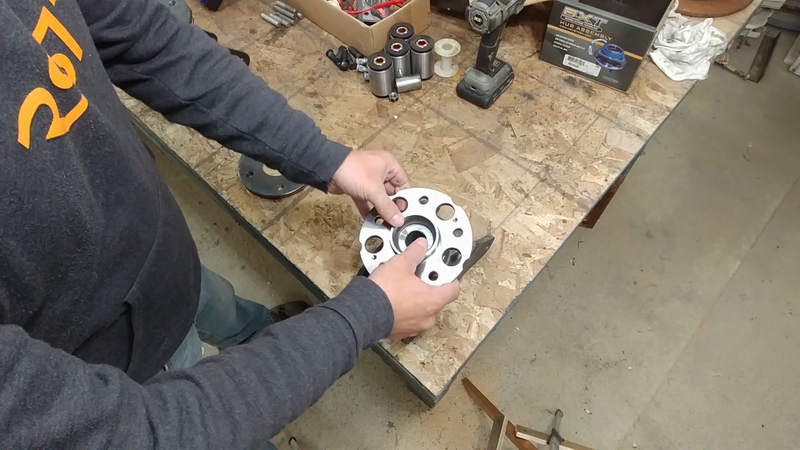
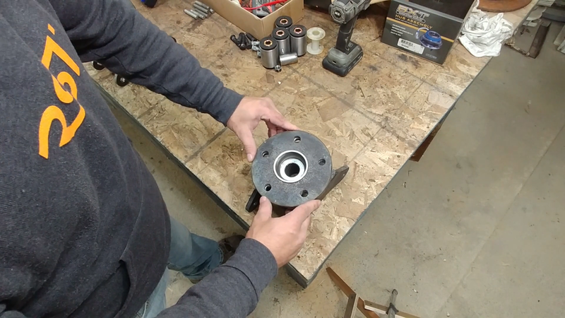
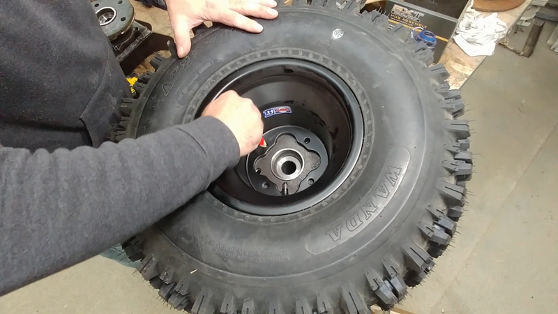
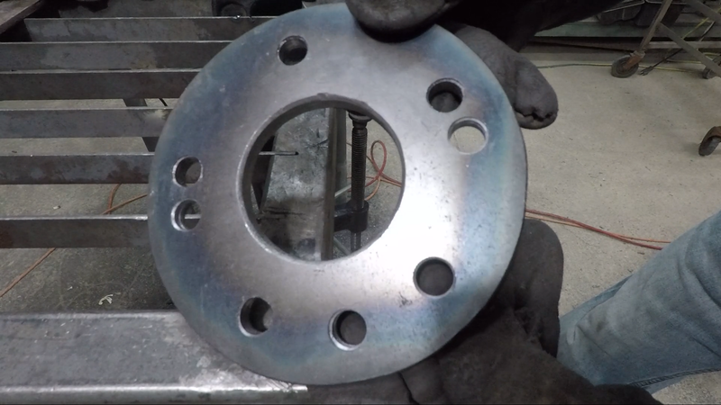
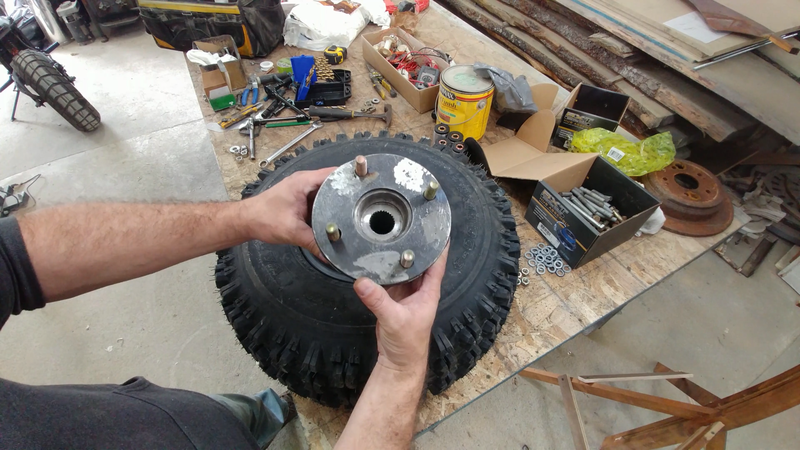
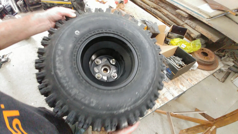
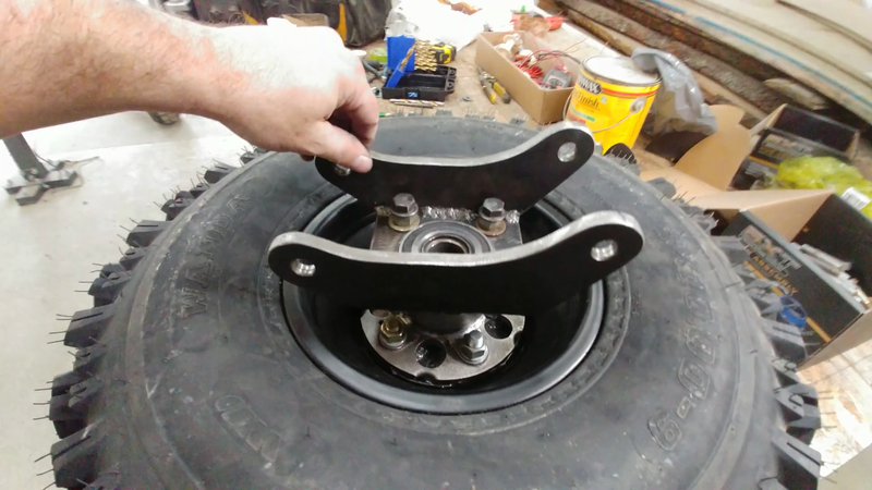
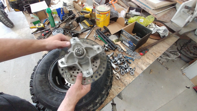
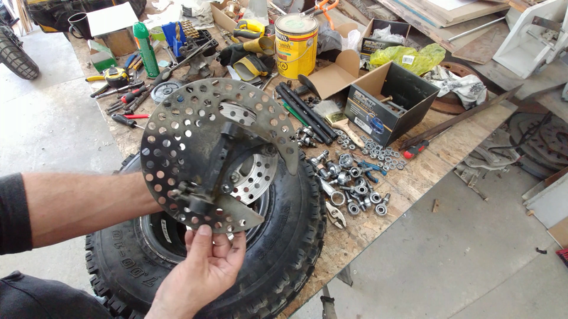
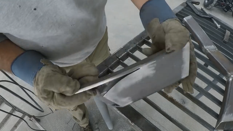
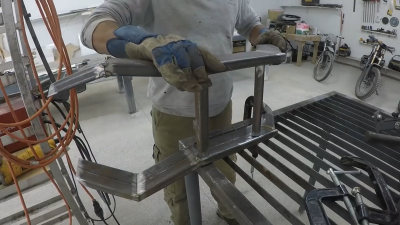
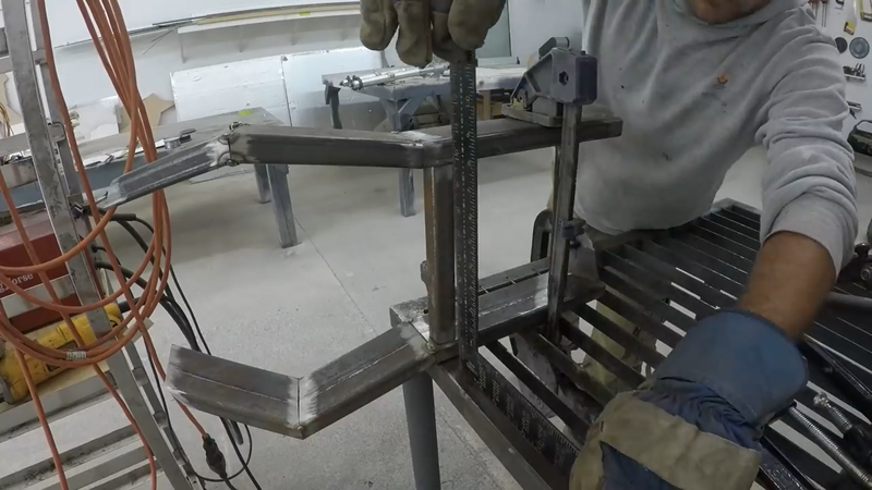
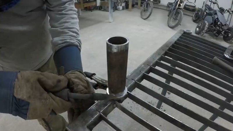
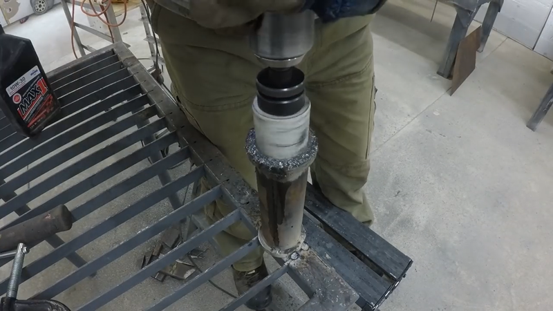
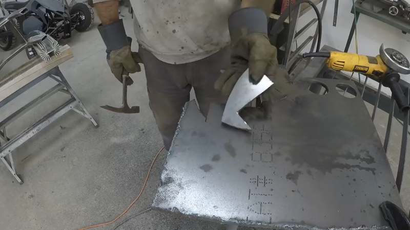
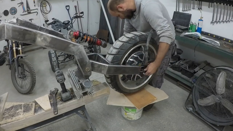
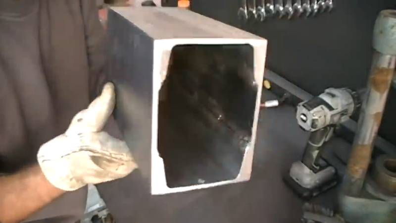
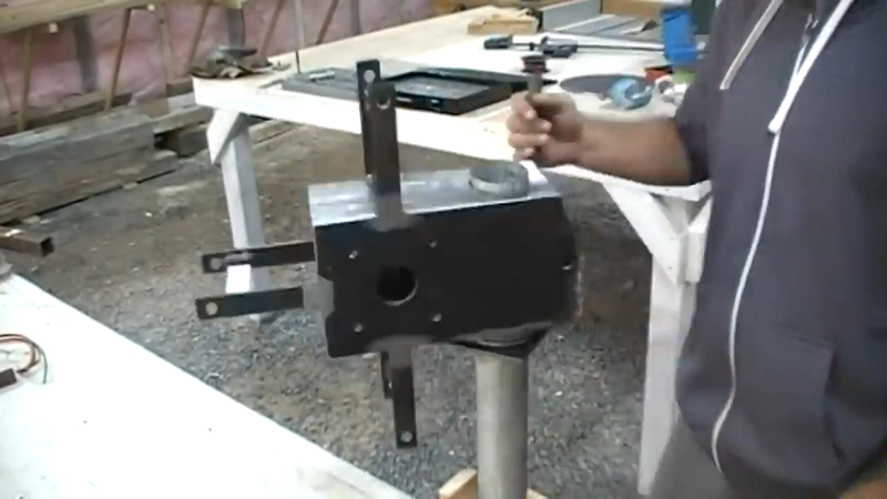
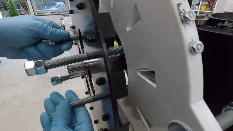
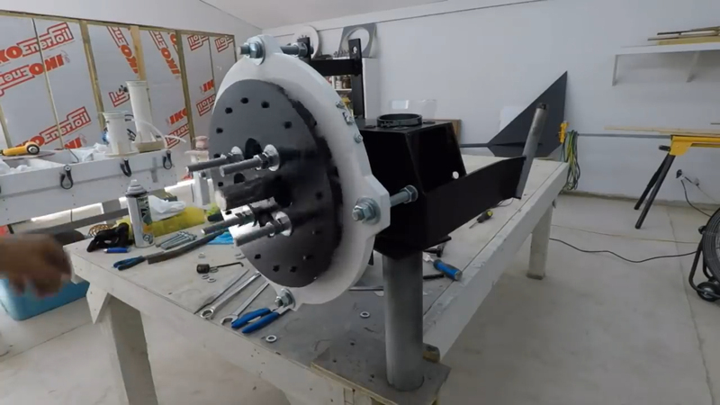
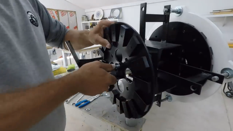
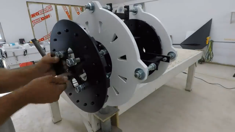
I began this stage of the build by fabricating some custom rear axle housings out of 3/8" steel plate to couple with the Honda CR-V wheel hubs/bearings and axles that will be installed later. I'm using these because I've chosen to install a CR-V rear differential as well (fitted with a limited slip conversion kit), so the drive components need to match up. Unfortunately, the CR-V wheel hubs are 5 bolt and don't match up with the 4 bolt 9" atv wheels that I'm using, so I had to make hub adapters to bolt up with them. The wheel hubs fit perfectly inside the wheel rims, so I used the bolt holes in the rims as a pattern to trace their location onto the new hub adapters and drilled them out.
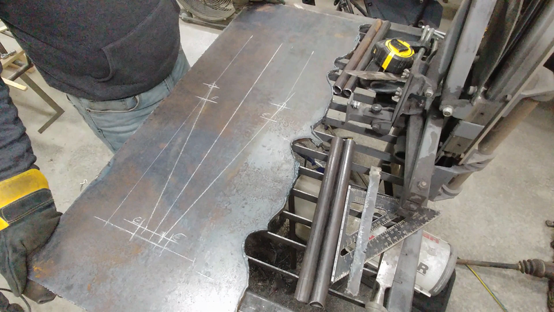
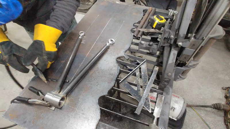
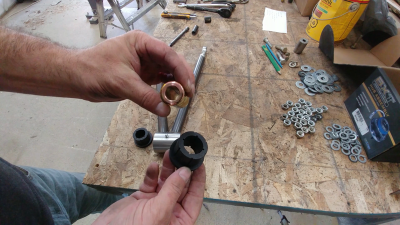
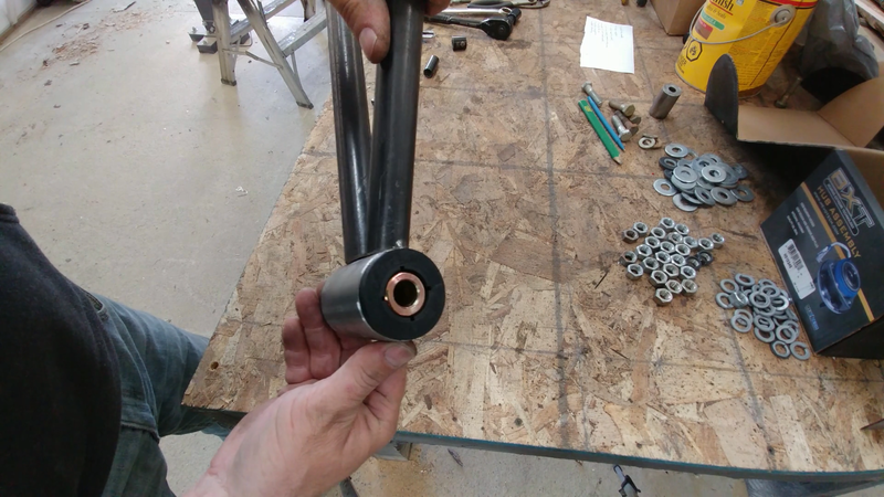
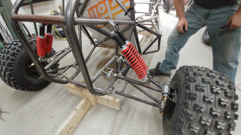
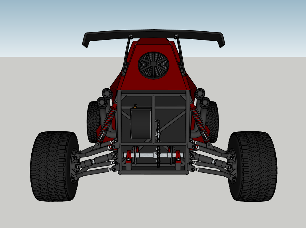
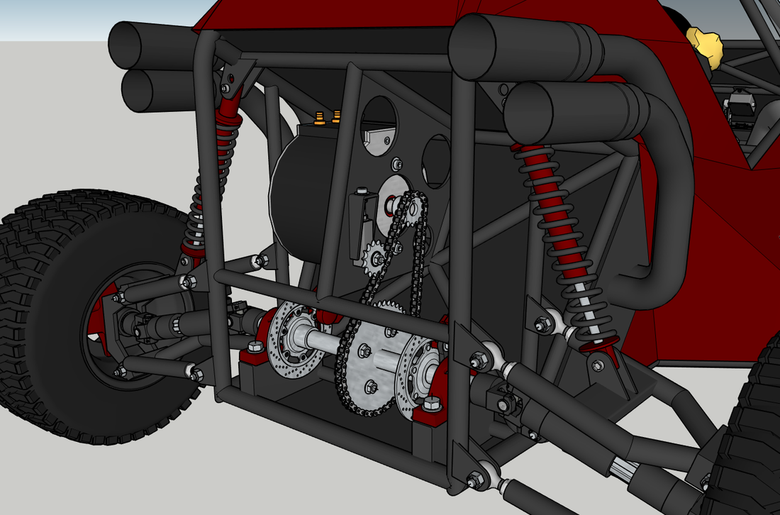
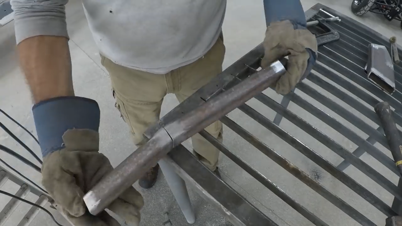
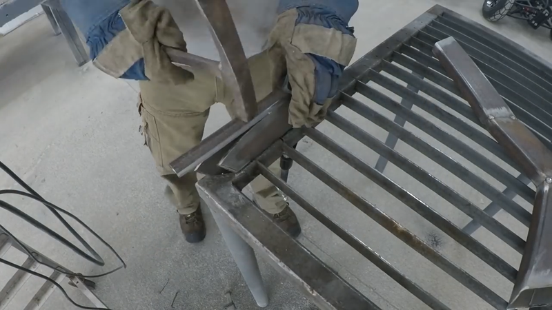
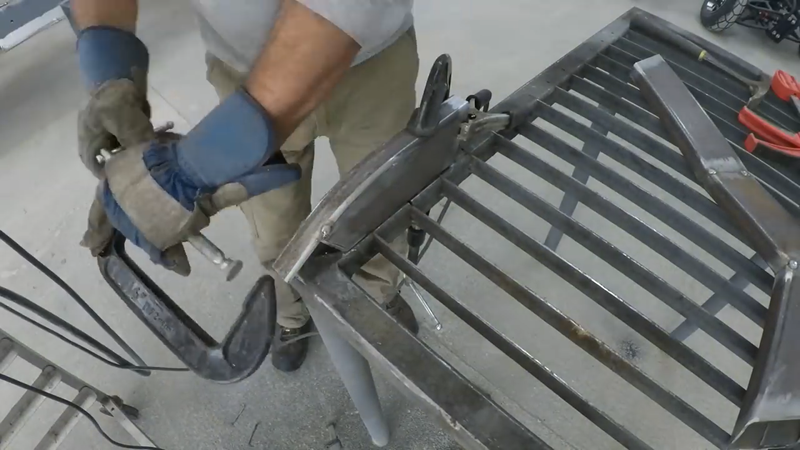
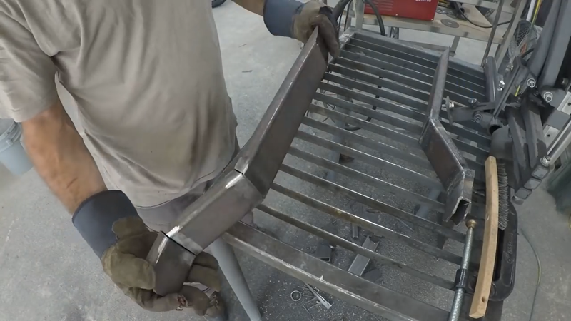
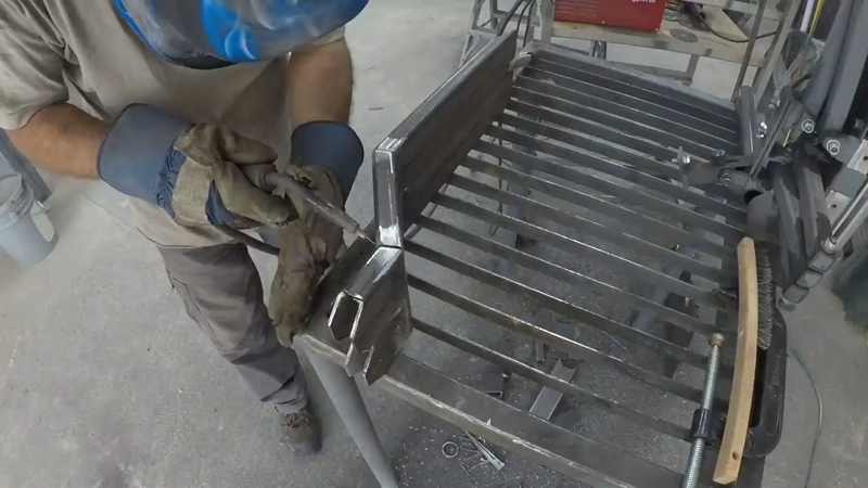
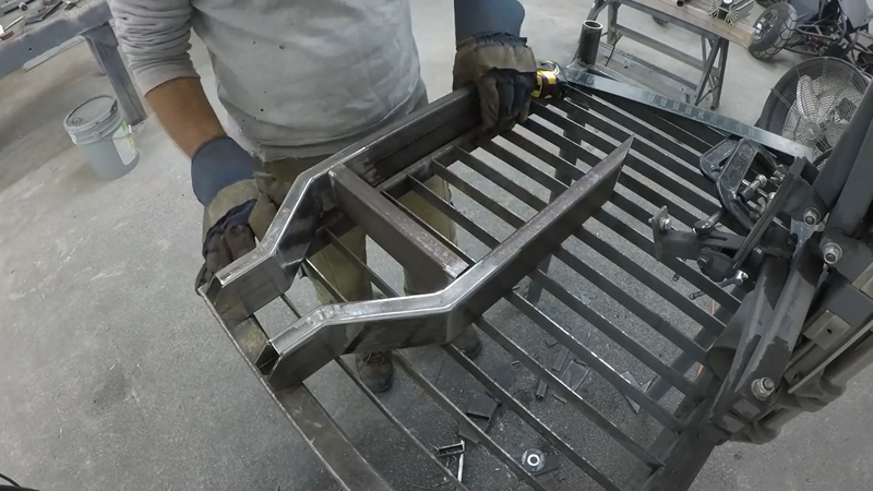
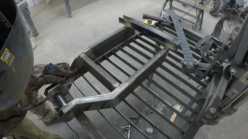
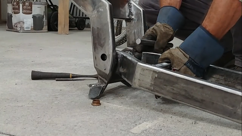
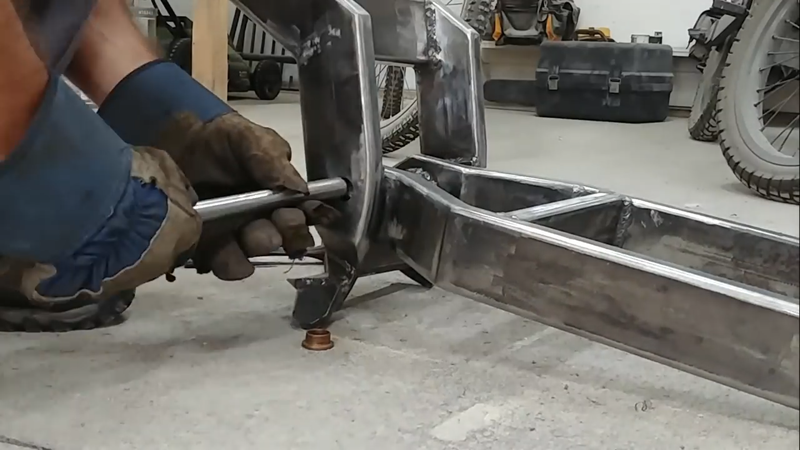
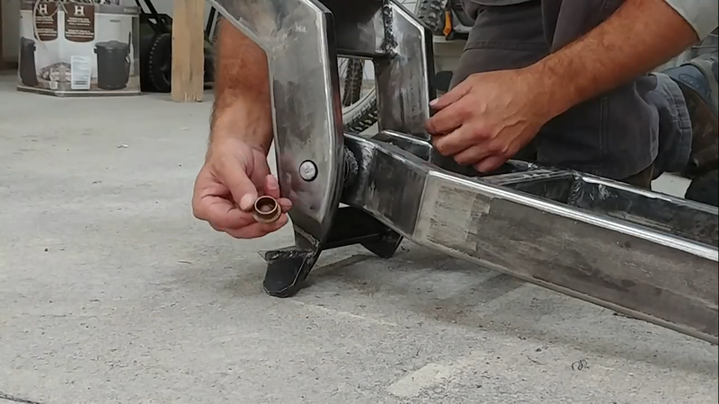
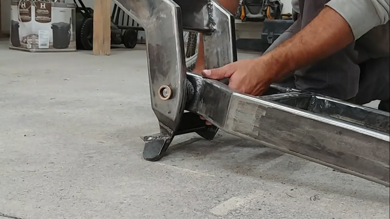
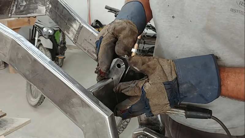
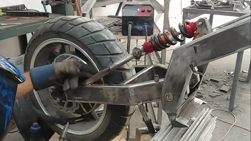
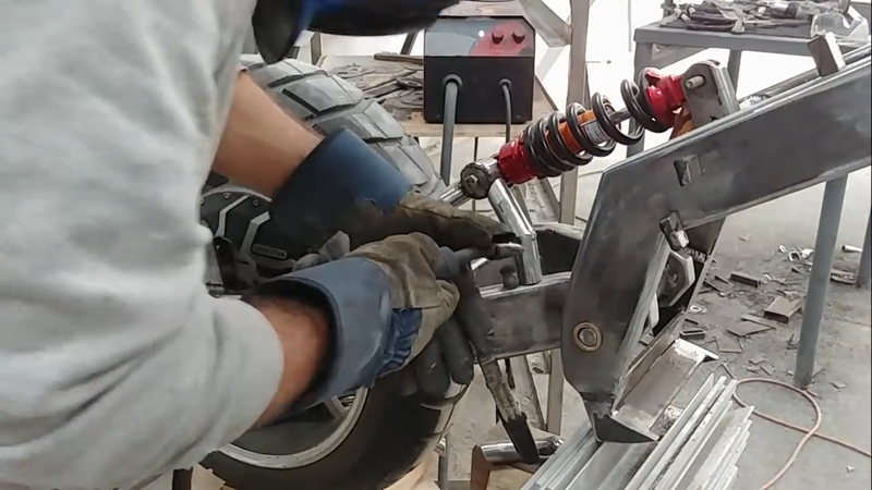
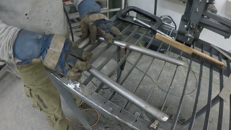
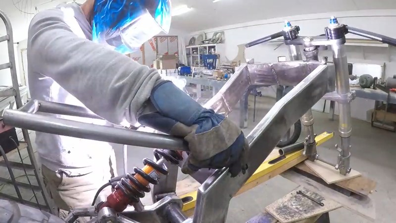
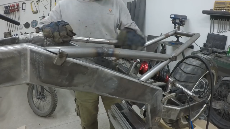
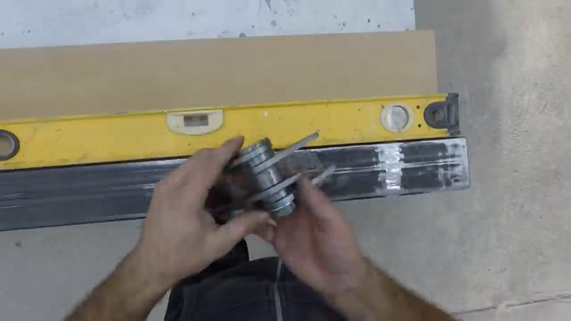
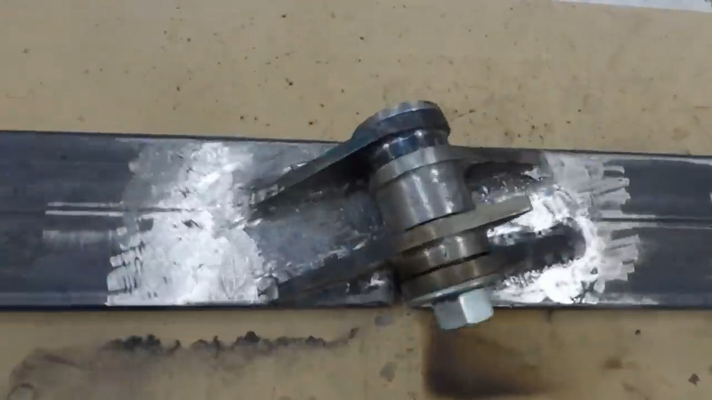
After the rear axle housings and detachable hub adapters were made, I then built the control arms for the rear double wishbone suspension using 1"x0.12" DOM tubing. These were designed with a specific geometry that will adjust the camber of the wheels when the shocks are compressed to increase anti-roll stability. I used 1/2" heavy duty heim joints to connect the arm ends to their mounts on the chassis, and weld-on polyurethane/steel bushings to connect the arms to the axle housings. Two 14" 400 lbs coil-over shocks where then fitted to each side.
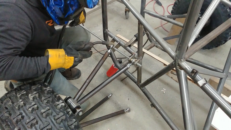
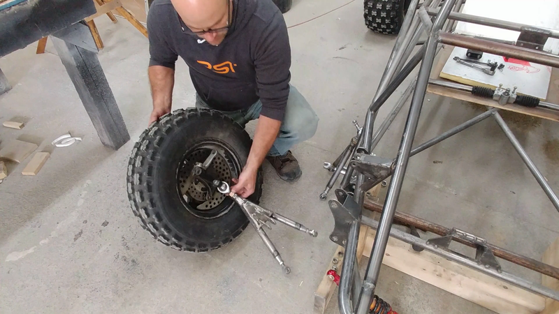
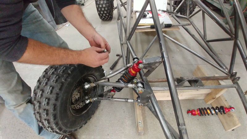
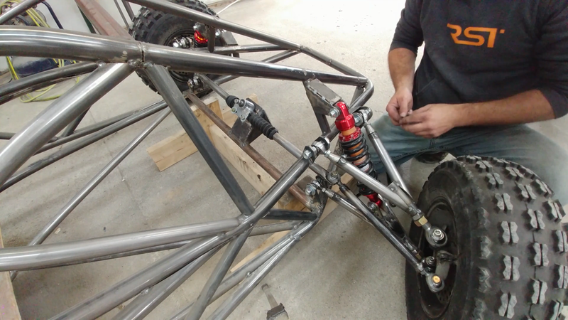
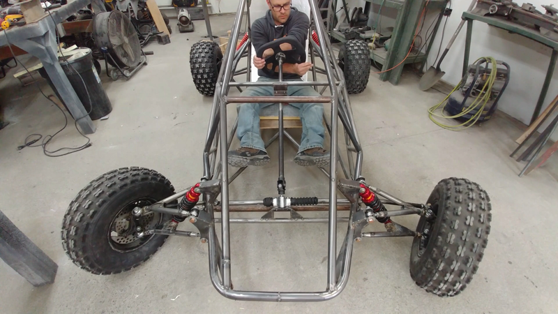
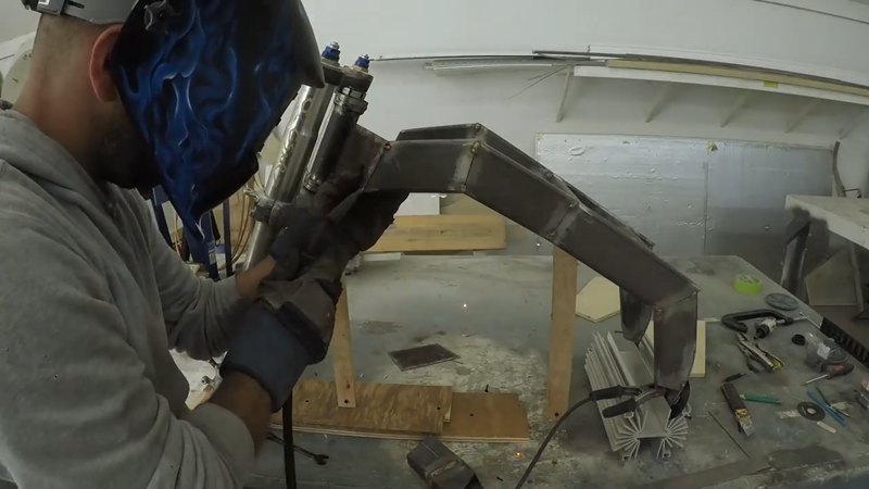
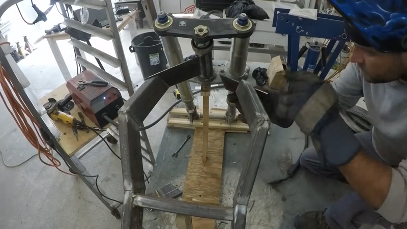
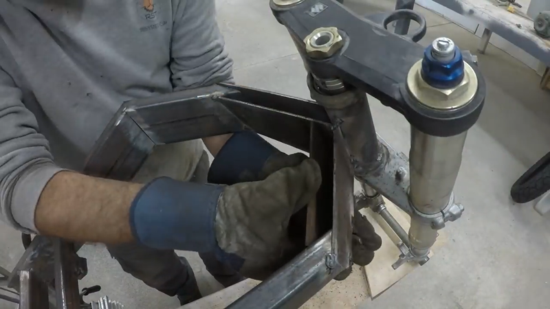
The front suspension was tackled next. The front of the chassis is low and wide so the control arms needed to be quite a bit shorter, and I had to be careful to allow enough room for the 11" 800 lb shocks to travel between the upper arms because they needed to be mounted to the lower arms due to the height constraint. I used heim joints to attach these arms to the chassis as well, but used ball joints to attach the arms to the steering knuckles, which were recycled from an old Yamaha Banshee atv.
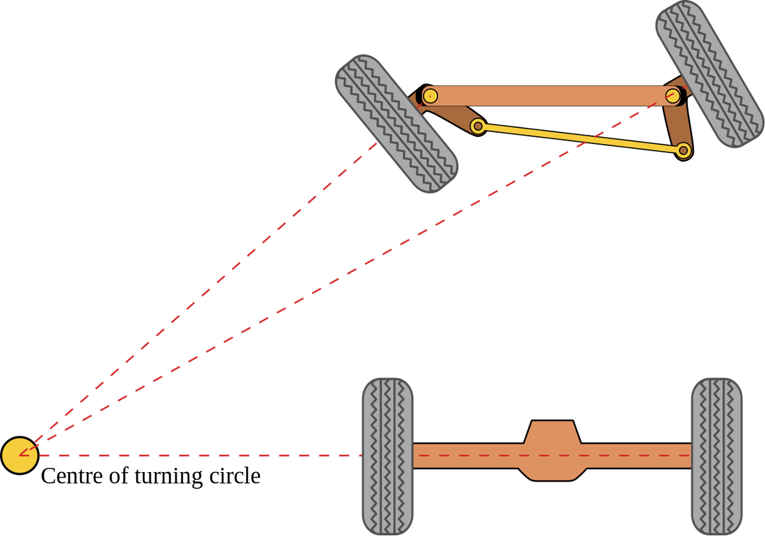
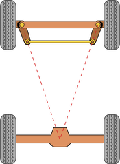
The only modification that I had to make to the knuckles was adjusting the angle of the steering arms relative to the rear axle to achieve proper Ackermann steering geometry. The steering arms need to point at the center of the rear axle to create a geometry that causes one wheel to turn more than the other when cornering. This compensates for the different turn radii that each wheel travels around a corner; the outside wheel will travel around a large radius than the inside wheel, so the angle of the outside wheel should be less than the inside wheel to minimize tire wear. Because the crosskart has a longer wheelbase than the Banshee that the steering knuckles came from, the Ackermann geometry would have been off if the arms weren't adjusted accordingly.
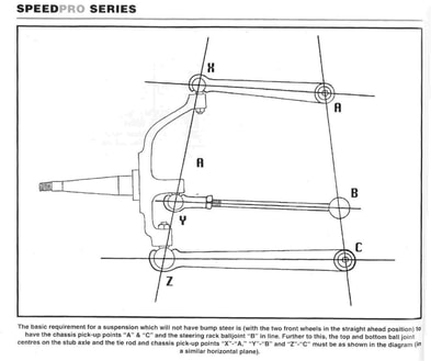
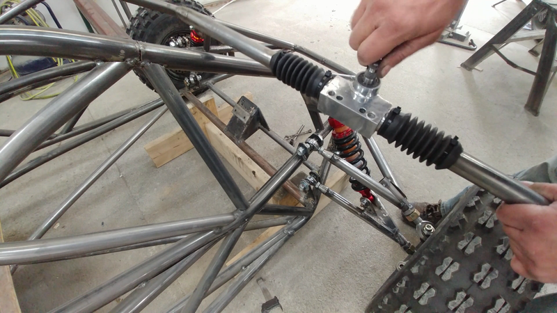
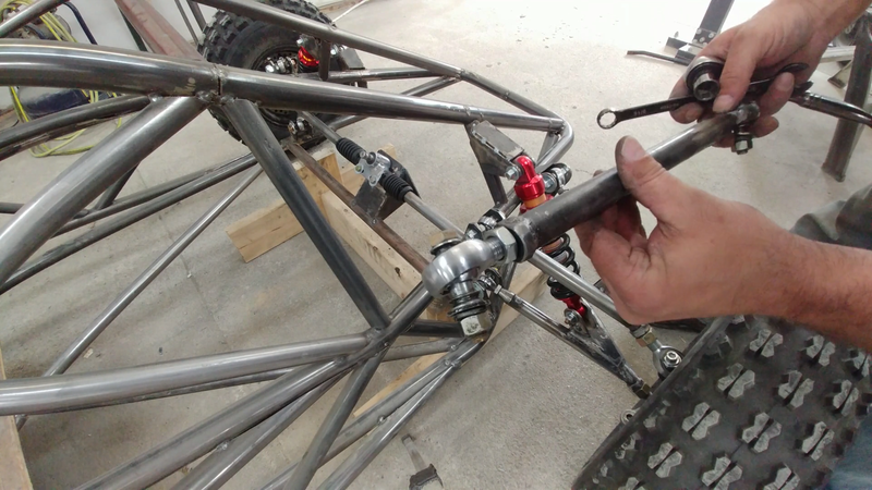
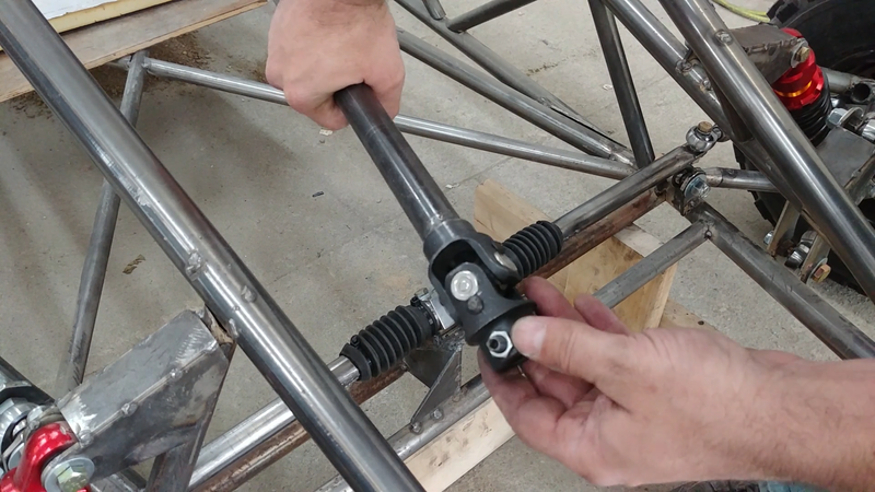
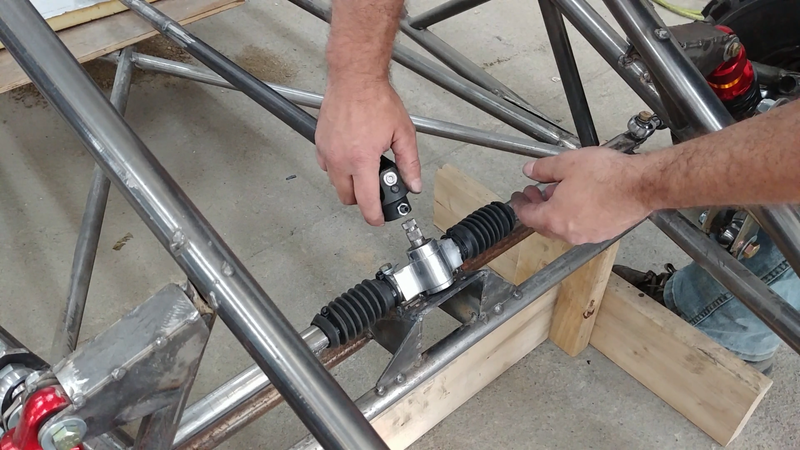
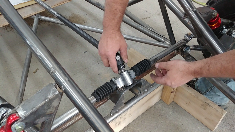
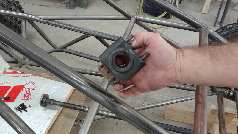
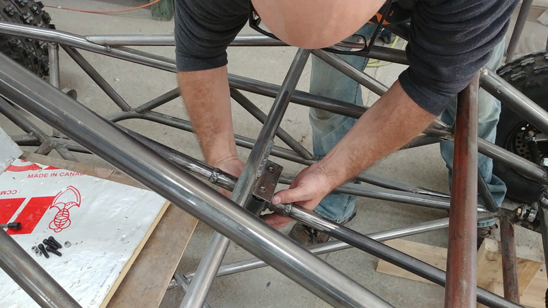
I then installed the steering rack, column, and tie rods. The tie rods are positioned at a certain height and angle relative to the control arms to minimize bump steer. Bump steer is the tendency of the tie rods to push or pull on the steering knuckle when the suspension is travelling up or down, causing the wheels to turn (or toe out) slightly, which affects handling and tire wear. If a tie rod or tie rod end is too high, too low, too short or too long for the suspension geometry, then bump steer will be increased. Simply put, to minimize or eliminate the effect, the control arm and tie rods need to be parallel with each other, and the chassis pick-up points and rod ends need to line up as the image below shows.
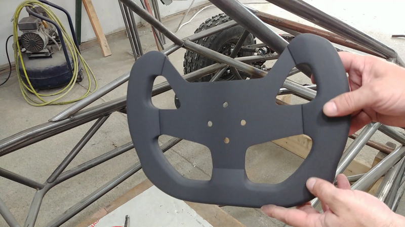
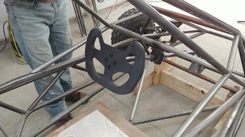
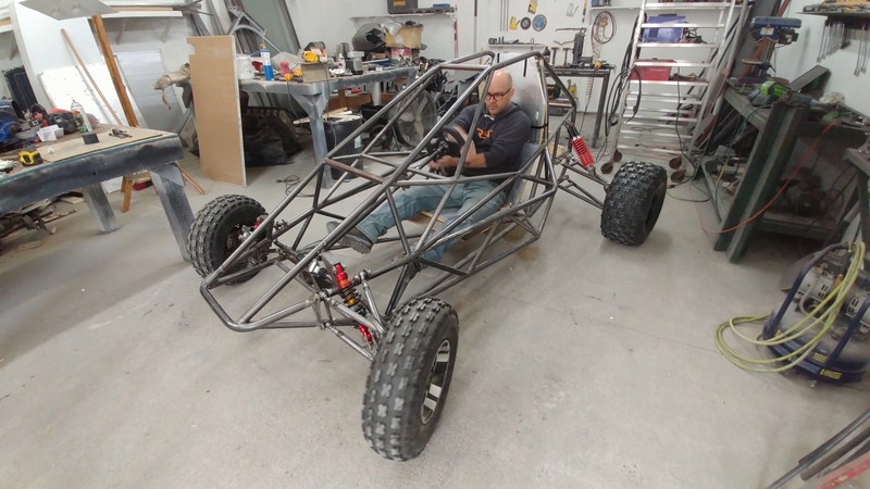
I then made a custom steering wheel. It's currently bolted to the column, but I'm going to add a quick release mechanism before painting to easily remove the steering wheel when I need to get in and out of the kart. You can check out how I made the custom steering wheel in the next post.
1 Comment
In this video I begin building the 55 kw off road electric crosskart buggy. Crosskarts are basically large, powerful off road go-karts built for racing on dirt and snow/ice tracks. I won't be racing this machine, so it's being built with more aggressive tires and a higher than normal ground clearance for ripping around in the trails.
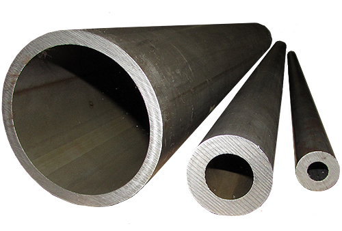
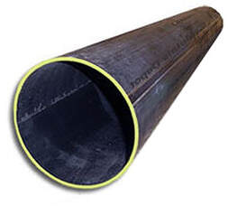
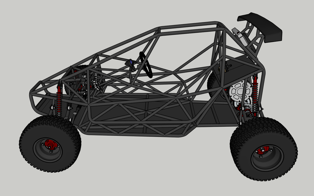
The chassis is made with 1.25" and 1" diameter x 0.12" thick wall DOM steel tubing. It can also be made with the same size HREW tubing, which is similar to DOM in dimension but has a welded seam and is more affordable. DOM is basically welded tubing like HREW that's been worked over a mandrel and ground and polished to precision inside and out so there's no welded seam to deal with when it's finished. DOM is slightly stronger than HREW, but not necessarily required for chassis building unless race regulations call for it.
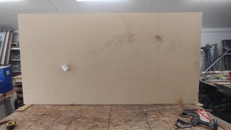
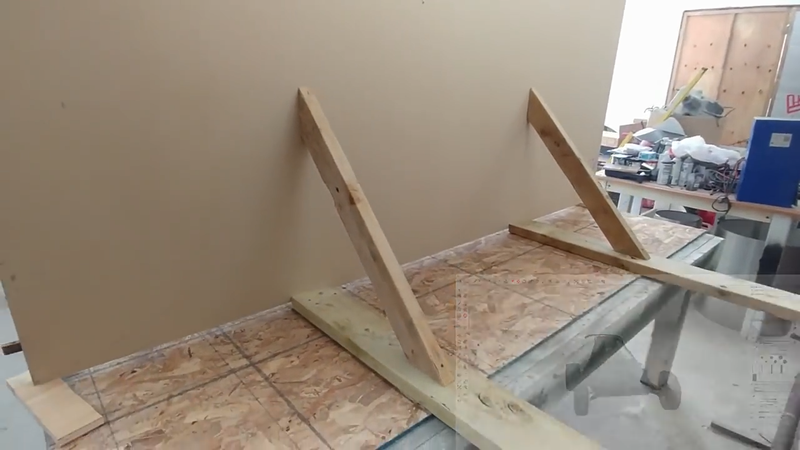
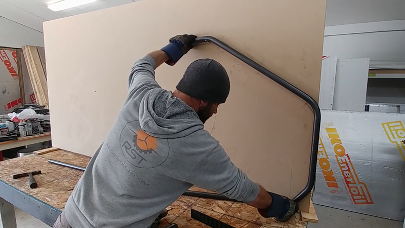
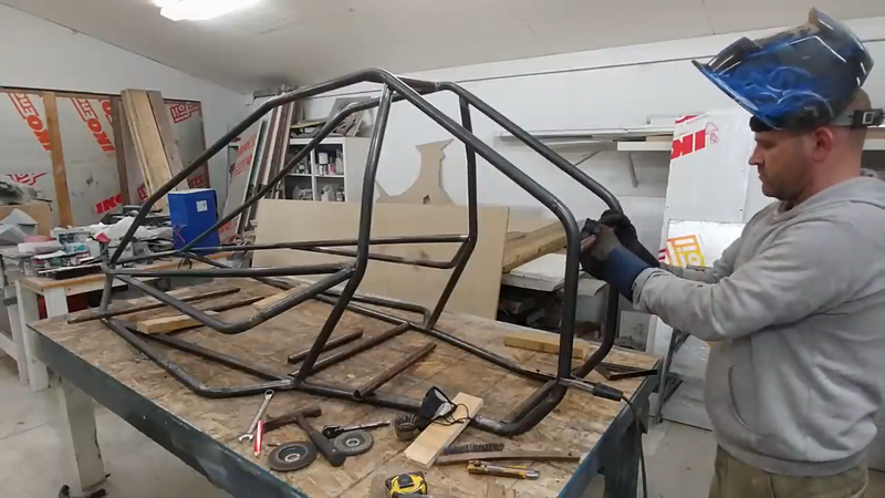
I first begin the build by laying out the bottom and side profiles of the chassis on a level workbench and a sheet of MDF that was attached at a right angle to the bench with 2x4 wood braces and screws. The reference lines drawn represent the center of the tubing, and make it easier to measure, mark, and fit each piece. The chassis was built in two halves that were later joined with crossmembers.
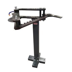
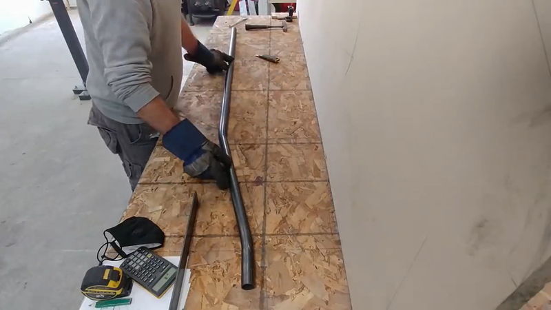
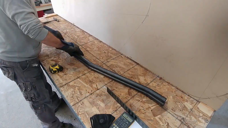
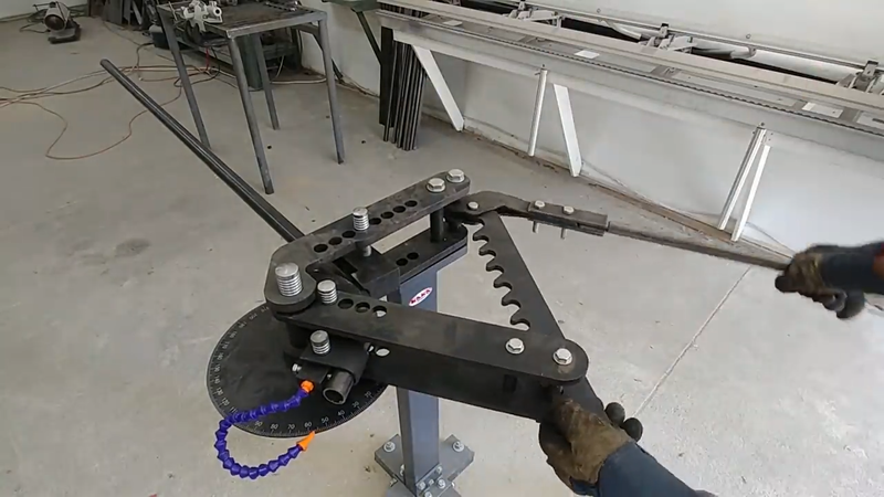
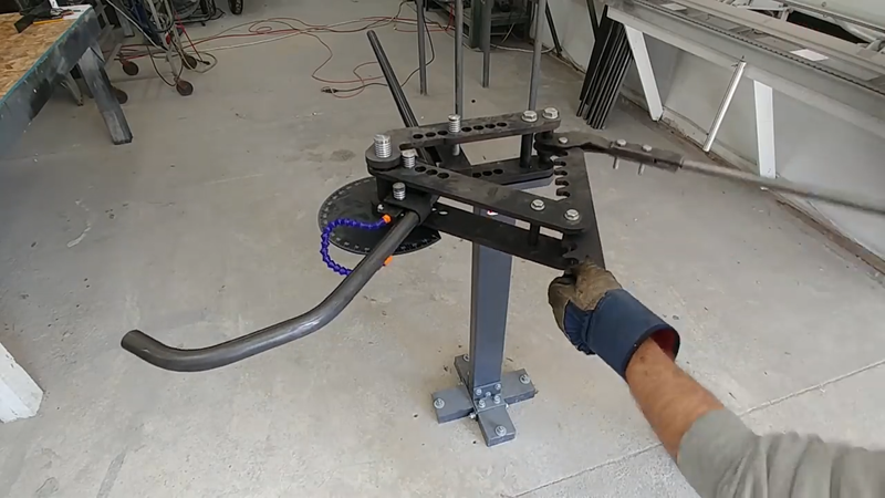
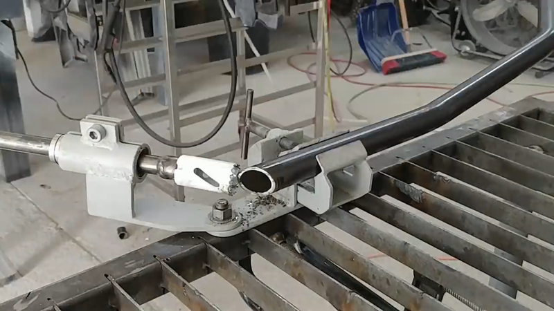
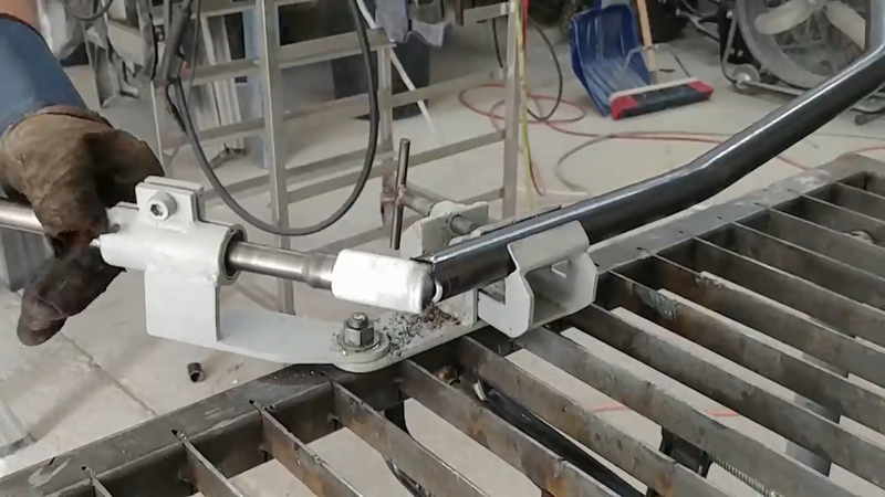
I used my TB-3 rotary draw bender from Kaka Industrial to bend the tubing. It's a bit pricy for a manual tool and might be a bit too much for the avg DIY'er to invest in, but if you're into this kind of stuff and plan on building more than one tube chassis in the future, then forget about miters - this is the tool for you. It works great, and I'm really happy to have it in the shop. This bender saved me a lot of work.
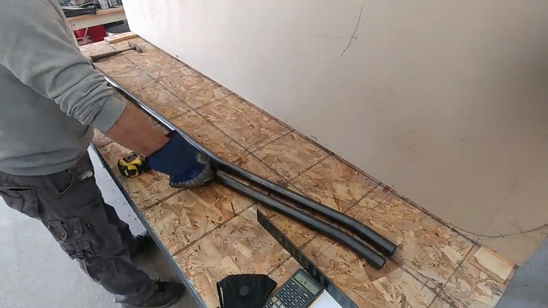
To avoid making mistakes, I bent each piece for both sides of the chassis and placed them next to each other on the layout lines to ensure they match in length, bend angle, etc.
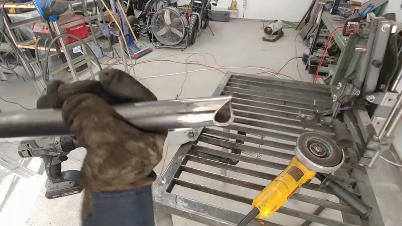
When necessary, I used my DIY tube notcher to notch the ends of the tubing where it needs to marry with another piece. The tube notcher saves a lot of work compared to using an angle grinder and it makes clean cuts that fit tightly with no gaps to save more time and $ when welding later. When I was satisfied with the fitment of each piece, they were tack welded in place.
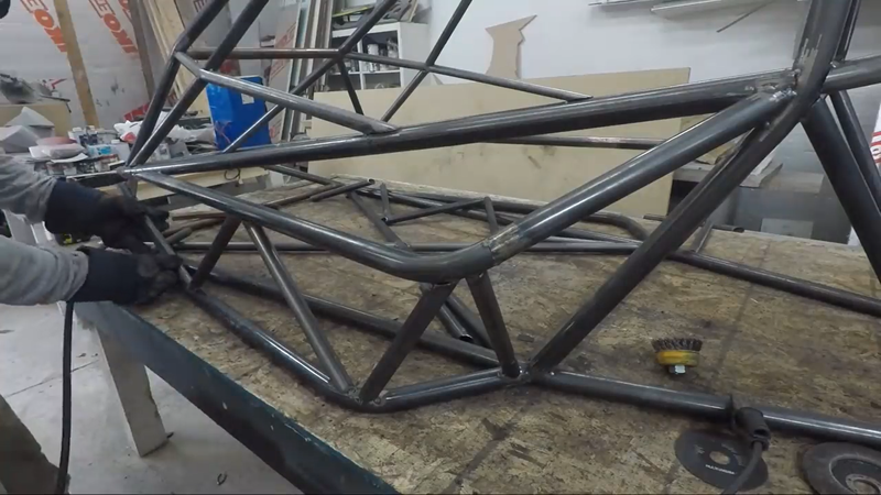
When the two halves of the chassis were finished, I removed the upright plywood from the bench and set up the halves so they were lined up with each other and spaced the right distance apart, then cut and welded the crossmembers between them. When the crossmembers were in place, I moved on to the diagonal bracing. The bracing went in the bottom, sides and back of the chassis. Its purpose is to form a truss assembly in these areas so they can support a load at any point and transfer it to the suspension, similar to how the roof trusses in a home are designed to carry and transfer a snow load from the middle of the roof toward the exterior load bearing walls.
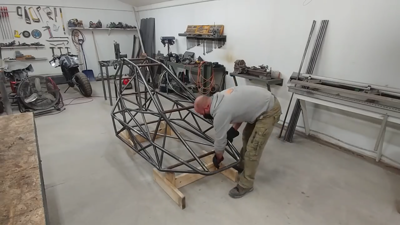
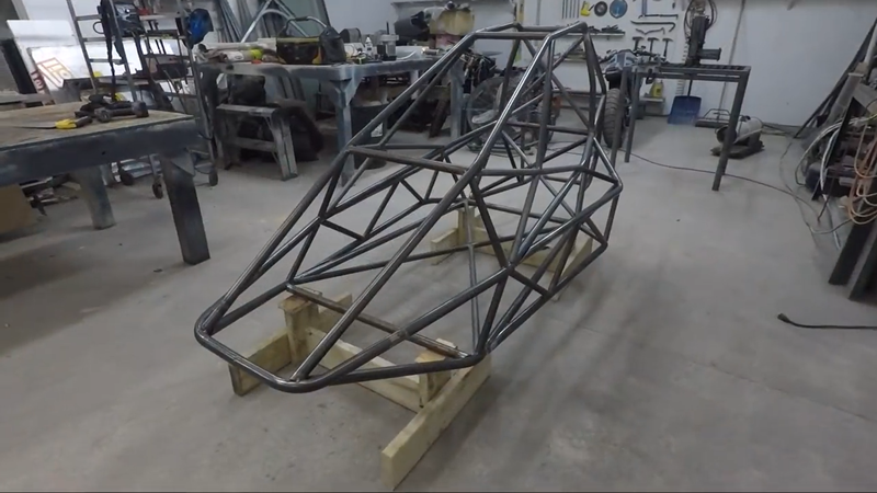
Once the halves were joined and the bracing was installed, I built a couple of wooden stands to set the chassis on at the desired (unloaded) ride height to prep for the suspension build. You can read more about that in the next post.
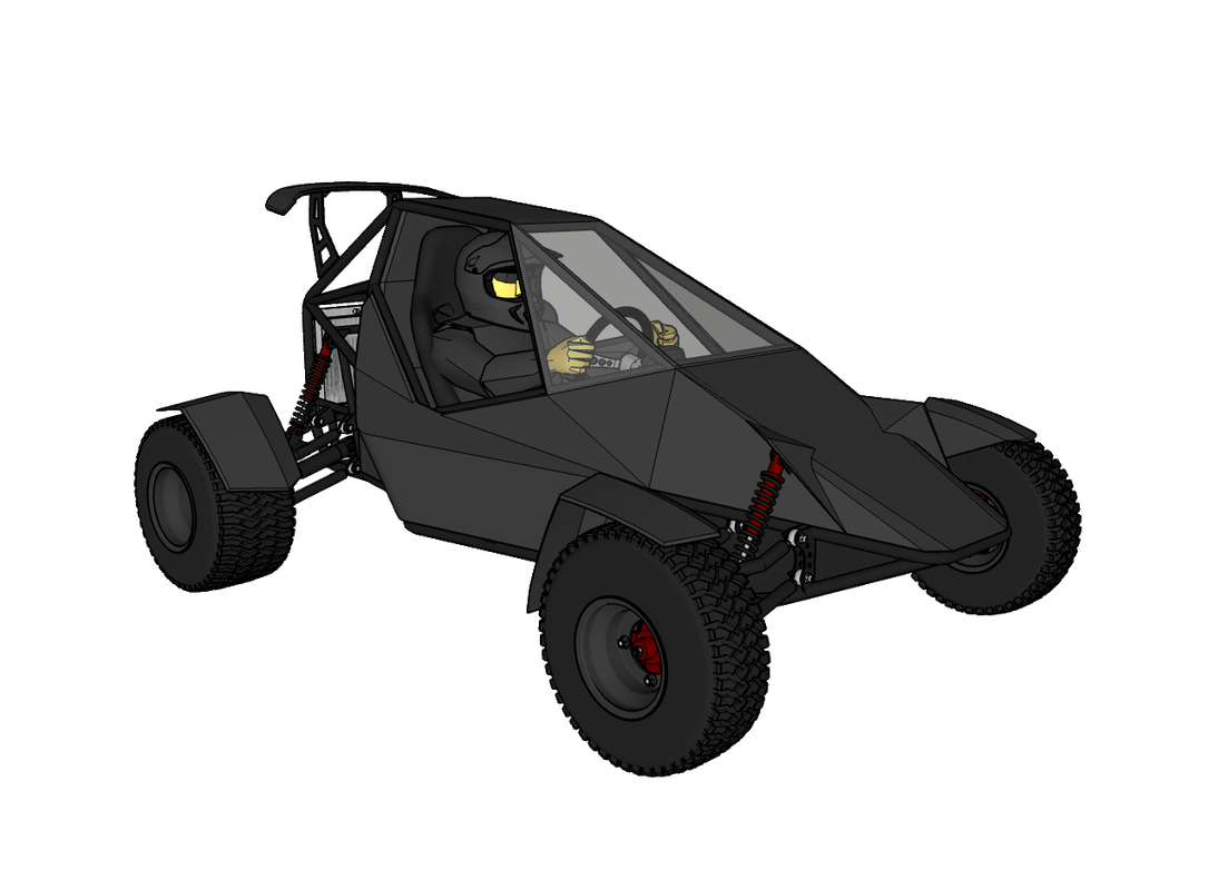
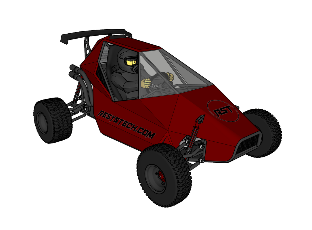
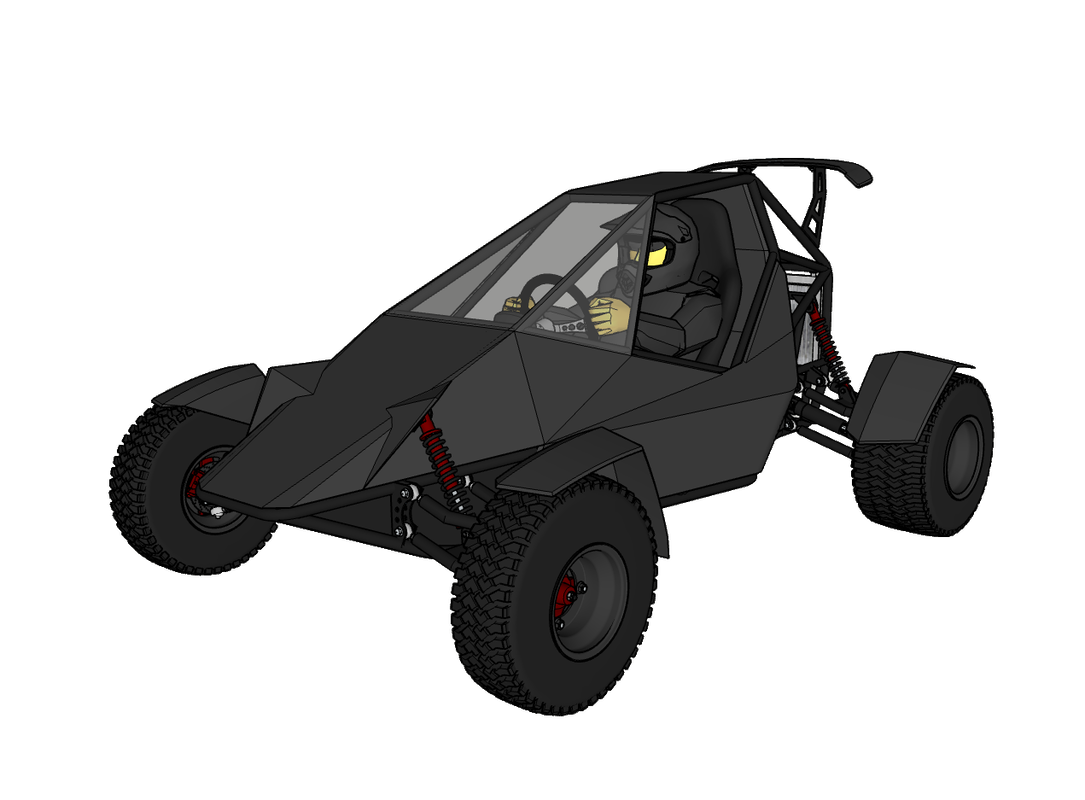
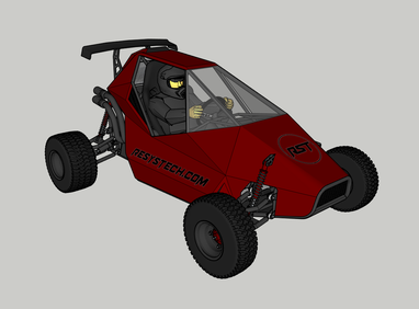
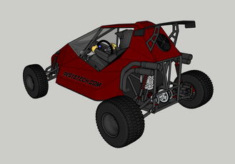
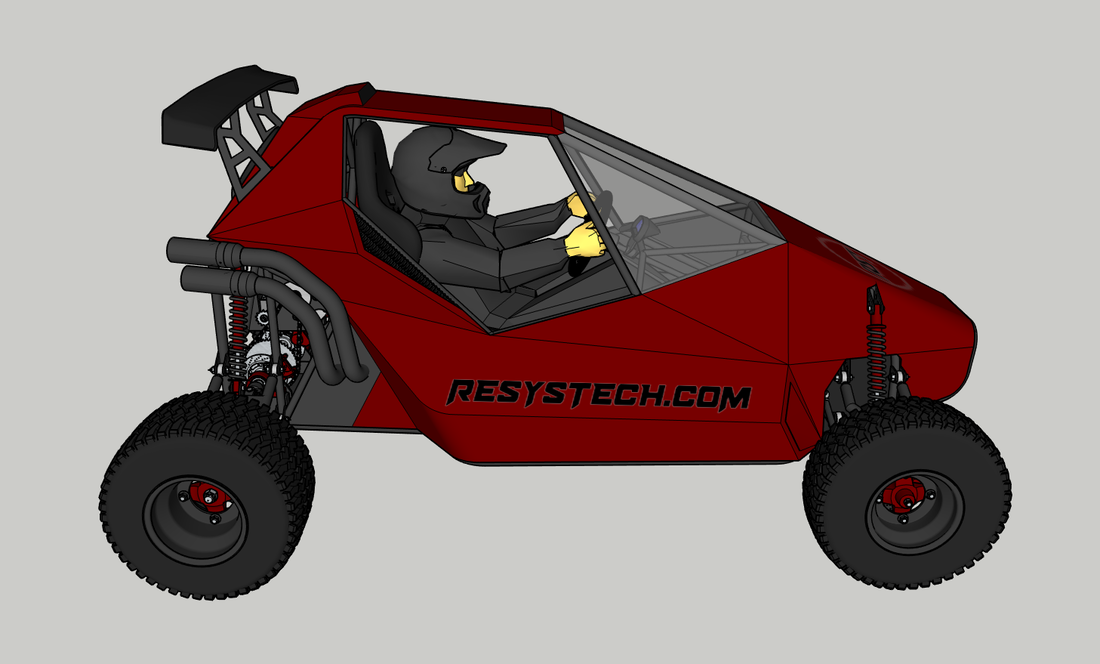
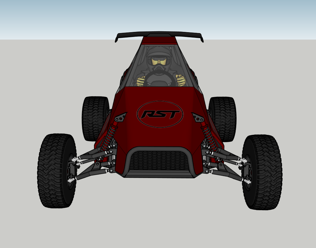
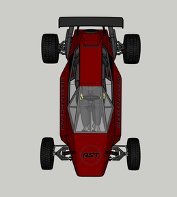
As per usual, I decided to change things up at the last minute. The more I looked at the original plan, the more I disliked it. It's too goofy looking, for one. The new design is sleeker and more aggressive.
The original is overcomplicated. The battery or specifically the battery box involves a lot of work, its position would make it a PITA to service later and raised the overall height and center of gravity, which increases roll potential, weight and the material needed to build it. The forced air TMS would also be an unnecessary feature that made me uncomfortable. Forced air cooling directly through the cells works fine in a controlled environment like a house or workshop, but with the constant humidity changes outside, I prefer to hermetically seal the battery. Given that it's dramatically oversized for the job, I highly doubt it will experience any heat build up issues when used.
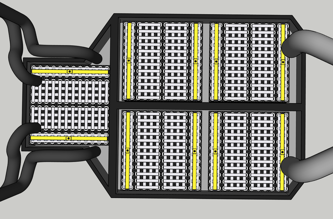
Instead of multiple modules being located below the seat, I split the battery into two modules with a 24P15S configuration on either side of the seat which will be connected in series to form 24P30S and have a single external BMS. This allowed me to lower the seat ~5" and subsequently the overall height of the kart without affecting the 11" of ground clearance below, which also lowers the CG and spreads more weight over a wider area to help with cornering stability.
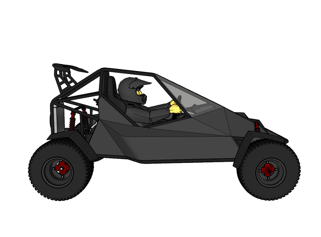
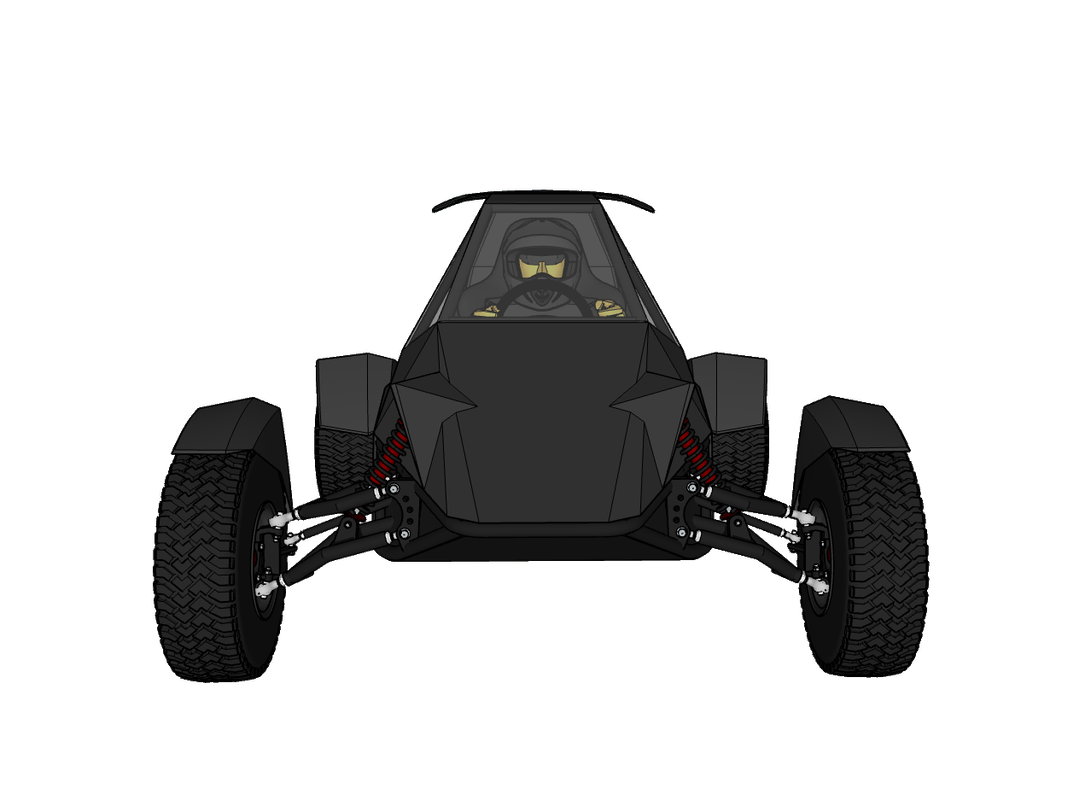
The cabin was also narrowed and the TMS input in the blunt front end was removed and the front reshaped with a portion of the bottom angled up for better ground clearance and aerodynamics. I also added cowls over the front upper shock mounts and wheel fenders. These changes helped to lower the curb weight by ~100 lbs.
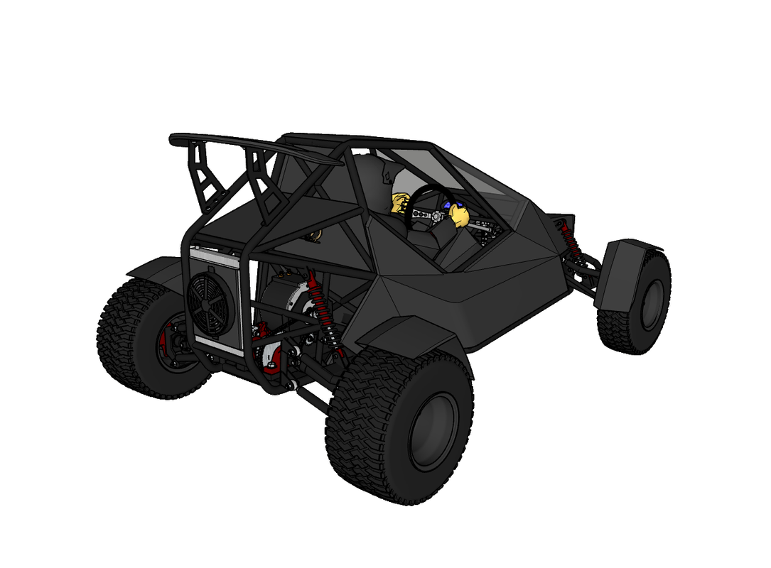
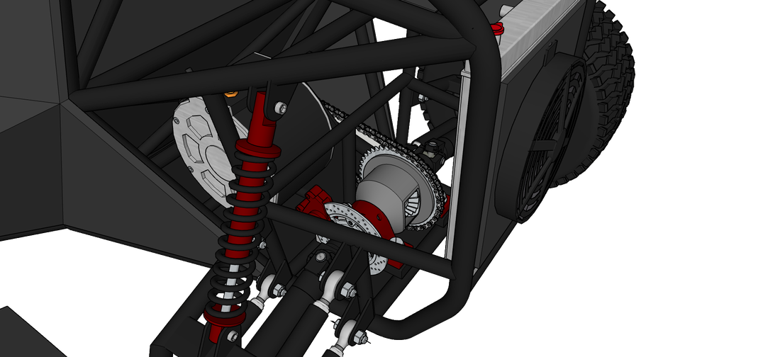
The last major change is in the drive train. The solid rear axle is being replaced with a 5" open differential from an '06 Honda CRV. An open diff isn't ideal, but I'll be installing an aftermarket limited slip kit as well to convert it to a LSD. This will eliminate any understeering that would have otherwise happened with the solid rear axle because the wheels need to travel at different speeds when cornering to compensate for following different radii. A solid rear axle works fine in the dirt where one of the tires can easily spin to keep up with the other, but it's harder to do on the pavement and will result in faster tire wear and/or a trip into the ditch. The LSD allows the wheels to spin freely of each other, but will lock up the axles as if they're one solid unit if one of the wheels begins to spin and lose traction. This will make it ideal for driving safely on pavement but also for tearing up the dirt in the trail = a win win.
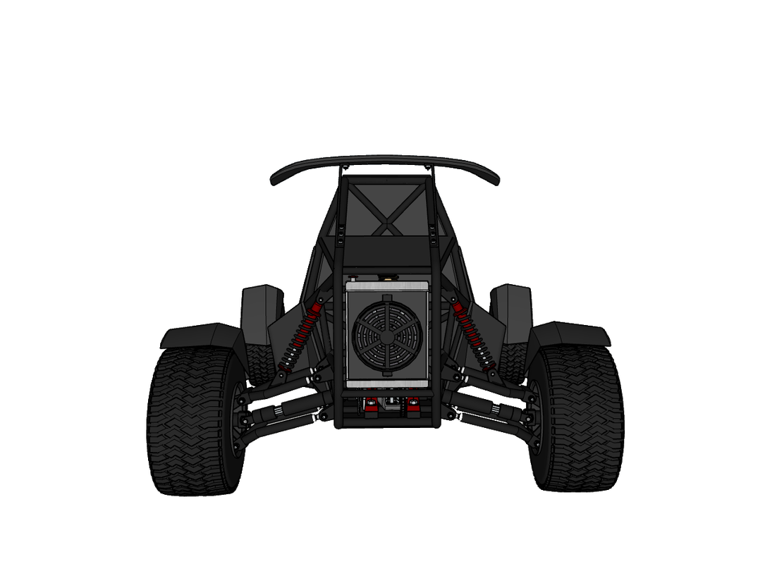
The LSD will be chain driven. The drawing shows the gear set with a sprocket in place of the large drive gear that would otherwise couple with a drive shaft. I omitted the housing in the drawing for the sake of seeing inside better, but the gears will need to be enclosed so they can be constantly lubricated without making a mess everywhere. I might change this configuration when the differential arrives and I can get better measurements to see what my options are and how I can modify the housing as needed.
I have to give a shout-out to Brian at XS Motorworks for figuring out this 'poor mans' LSD hack for DIY crosskarts and buggies. He's also building a crosskart atm, which is a little hybrid monster that he plans on racing against his friend. Check out his channel: https://www.youtube.com/channel/UCF6hn52lSuoXzIYnwLOUw9Q That's it for now. The tubing was delayed at customs for a couple weeks but arrived the other day. Just waiting for the new rotary draw tube bender to be delivered tomorrow. I'll be starting the build for sure next Monday. Updates to follow.
(click the images to enlarge)
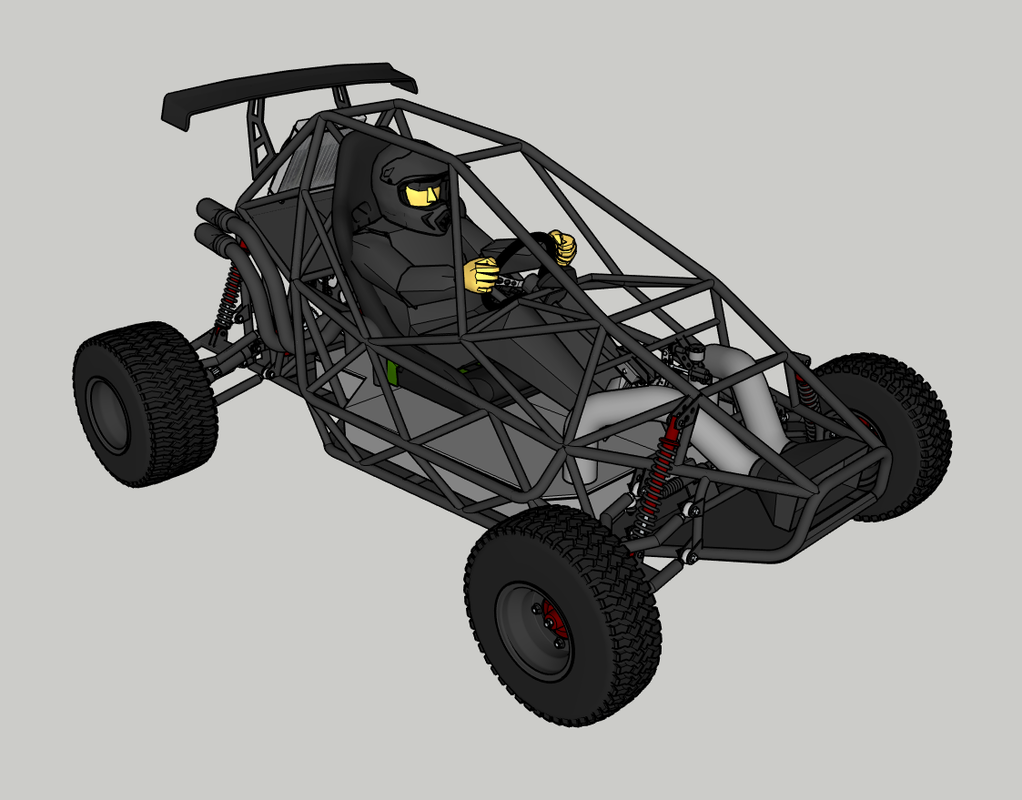
I've finished the crosskart CAD, for the most part. There are still a few things missing like the wheel fenders, coolant lines, etc, but there's enough detail for you to get a pretty good idea of what the end goal is for this project. If you haven't seen the previous posts about this crosskart, I recommend checking them out. They detail the motor, controller and battery specs (w/ source links) that will make up the 55 kW (73 hp) drive system.
The chassis will be made with 1.25" and 1" diameter x 0.12" thick wall DOM steel tubing. I incorporated a bit more bracing than most crosskarts would have because of the extra weight from the batteries and I want to make sure it's rugged enough to take a beating in the trails.
I chose independent double wishbone suspension for the front and rear wheels. The lower control arms are arched to provide more ground clearance (total 10"), and the upper arms are a bit shorter than the lower arms so they'll cause a slightly negative camber as the 15" coil-over shocks and 22" wheels travel upward and provide some added anti-roll stability when cornering. Max wheel travel for the front and back will be roughly 8", on par with most.
In the CAD you'll see that I have u-joints and telescopic PTO shafts making the connection between the rear wheels and the 1.25" dia. stainless steel solid axle mounted in the center, but I'm probably going to modify a couple of atv cv axles to use instead to help cut down on weight and increase transmission efficiency (cv axles are more efficient than standard u-joints). I'm not sure what I'm going to use for gearing yet, but it will either be 3:1 or 4:1 between the driven and drive sprockets. A 520 motorcycle chain will connect them, and 1.25" pillow blocks will bolt to the chassis and hold the axles in place. Of course, there's also a chain tensioner mounted beside the ME1616 motor to take up any slack.
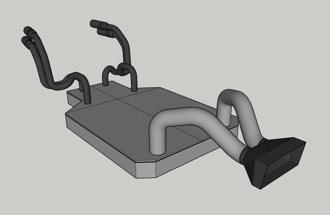
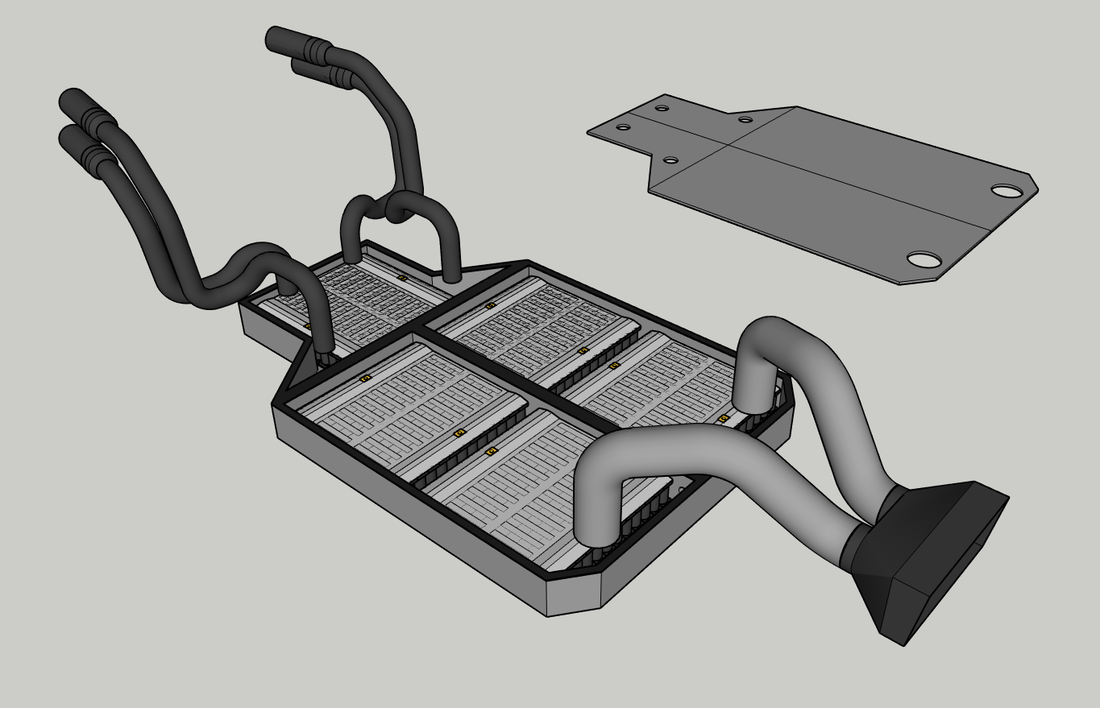
The exhaust pipes are actually just that - exhaust pipes, but for warm air being forced from the battery instead of burnt petrol fumes. As mentioned in the previous post, the battery will be overpowered for this application by more than 100A, which will cause it to operate cooler than it would if I build it to match the motor power specs. This allows me to get away with a simple forced air thermal management system for keeping the battery relatively cool.
Air will enter the system through the grill at the front of the crosskart, then travel around, between and over the cells from front to back and exit the exhaust pipes - each containing high flow inline blower fans that will turn on via a programmable digital thermostat when the temp demands to help compensate for the pressure drop in the system (caused by the drag/resistance the airstream will experience when travelling around the cells and duct cornering), and get the airflow moving faster when needed. All entry and exit points will have safeguards like drip loops to make water penetration to the battery impossible without completely submerging the crosskart in a water hole - which I would never do even if it weren't going to have an electric drive system.
I was originally going to braze together an aluminum box for the battery, but I've been considering using fiberglass panels and/or Coosa board. This would insulate the battery from the chassis and help keep me alive if anything crazy were to happen down there, and I think it would be easier to make it waterproof as well...with the exception of the TMS intake and exhaust ports, of course. I haven't brazed anything since high school over 20 years ago, so there's a pretty good chance that I would spend a lot of time chasing pin holes trying to make it watertight. But on the other hand, 90% of the box will have to be built in place due to space constraints (won't be able to get it in after the chassis' roll cage is welded in place). Either way, the cover will be bolted to the box perimeter in four pieces so that it can be removed at any time for servicing later. The seal between the covers an the box will be made with a continuous silicone gasket.
The radiator mounted on the back of the crosskart will provide cooling for the motor. Air will be forced into the radiator via the intake vents on either side of the cabin and the scoop on the roof, with help from a 12" fan. I avoided putting anything other than mechanical components in the front of the machine because I want a bit of a crumple zone there - if anything is damaged in an accident, I'd rather it just be tubing instead of other components like the rad or battery.
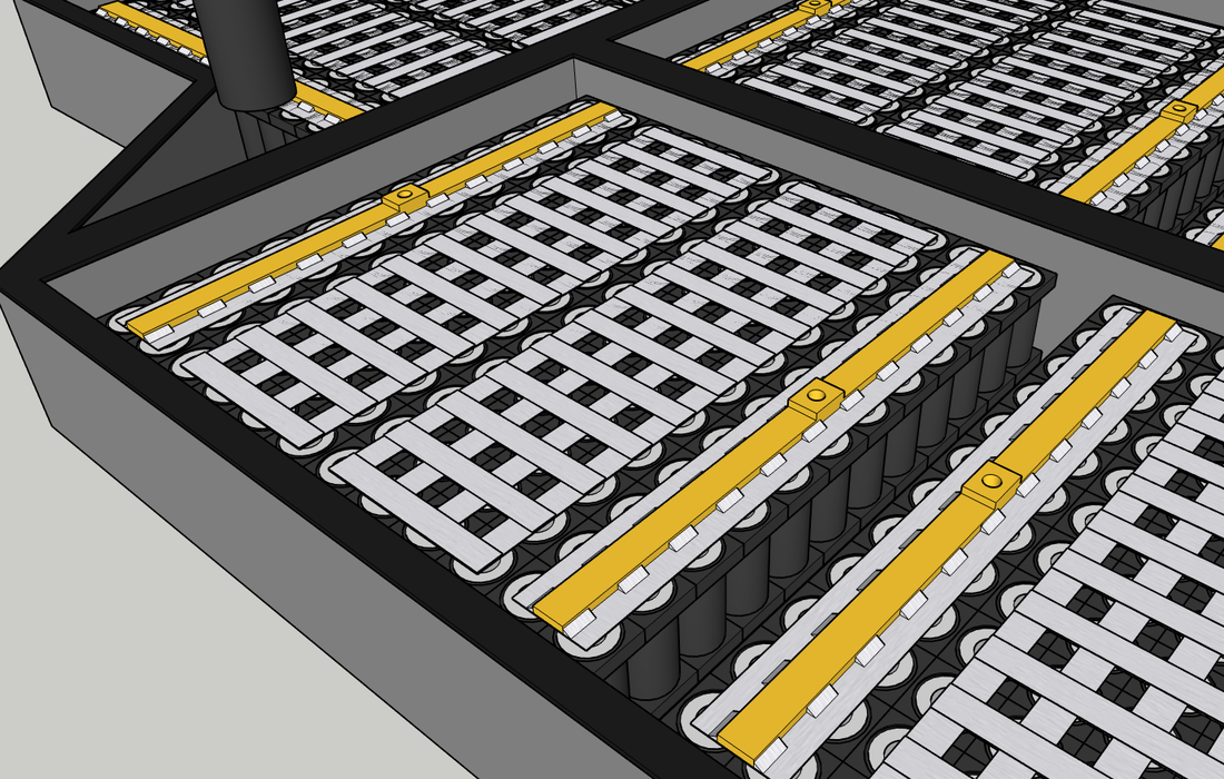
The battery will be made up of 5 series connected modules, each consisting of a 24P6S 5 Ah cell configuration to form a complete 24P30S, 120Ah/96V battery. I'll be using 0.2-0.3mm nickel strips to connect the cells, with every series connection in each module layered with enough strips to carry about 20% more current than the max continuous current that the 24P cells are capable of (ie: capable of carrying ~350-400A continuous). The first and last series connections for each module will be made with 1/4"x1" copper bus bars and nickel strips, with the copper being soldered to the nickel strips before they're spot welded to the cells to prevent overheating them with the soldering iron.
If desired, a person could incorporate two of the ME1616 motors to increase the power to 140+ hp and drive each rear wheel individually for better cornering on hard surfaces, or power the front wheels with the second motor to create a 4x4 machine, but you will need to use the more powerful 6 ah cells in the battery to handle it that load. That's it for now. As always, the plans will be available after the build has been tested. Tubing is on the way. I've got a small project to finish up for my grandparents which I might feature on the channel sometime next week to help fill in the gap between uploads. It's nothing spectacular but it is a useful device for seniors. More details on that and the crosskart build when the time comes.
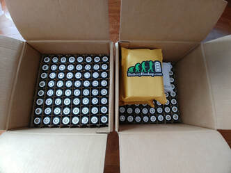
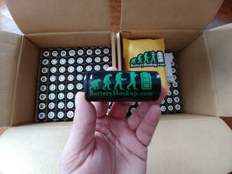
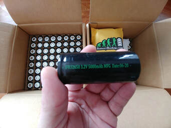
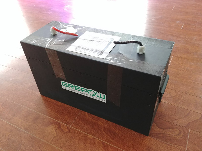
The cells for the buggy battery have arrived. I purchased these new 32650 LiFePo4 cells from batteryhookup.com for CHEAP. I don't think you're going to find a better price anywhere else. They're rated for 3.2V and 5Ah with a max continuous discharge of 15A (3C), and max pulse discharge (for 10 sec) of 50A. Max charging current is 5A (1C). They have another cell available rated for 6Ah capacity, 18A cont. discharge, 60A pulse discharge and 6A charge limit. Links for both can be found below.
As some of you already know, LiFePo4 isn't quite as energy dense as lithium ion but it is the safest type of lithium battery because it won't cause a runaway fiery explosion under your butt if a cell gets damaged somehow. This is the main reason why I use LiFePo4 in my projects when I can, aside from this type not containing cobalt.
The battery that I'm building for the buggy with these 5Ah cells will be a 24P30S configuration to produce 96V and ~11.5 kWh capacity, with a continuous discharge limit of 360A, pulse discharge of 1200A, and a charge current limit of 120A. This is well over the ME1616 motor's capability of 250A continuous and 600A pulse, so I don't expect there to be any thermal issues at all and have chosen to incorporate a simple forced air TMS into the buggy design to help the cells shed what little heat they might produce while driving.
11.5 kWh should give me around 200 km's of range per charge in the trails with regenerative braking. A person can use the 6Ah cells to get around 14 kWh in the same space if they want. But, Batteryhookup's customers have been reporting 5.5Ah+ capacity with the 5Ah rated cells while the 6Ah cells are at or just slightly above 6Ah, so in terms of cost per watt hour you'll be getting a better deal with the 5Ah cells ($0.19/wh vs $0.17/wh). I normally don't put on more than 80-100 km per trip when I go off-roading, so I opted for the more affordable cells.
The DOM tubing for the chassis will be here in a couple of weeks. I'll try to have the buggy CAD 'finished' and a few pics posted in a day or two so you can see exactly what I've got planned.
5 Ah cells: https://batteryhookup.com/products/new-battery-hookup-lifep04-32650-3-2v-5000mah-cells 6 Ah cells: https://batteryhookup.com/products/100-brand-new-lifep04-32650-3-2v-6000mah-cellsbatteryhookup.com/products/100-brand-new-lifep04-32650-3-2v-6000mah-cells
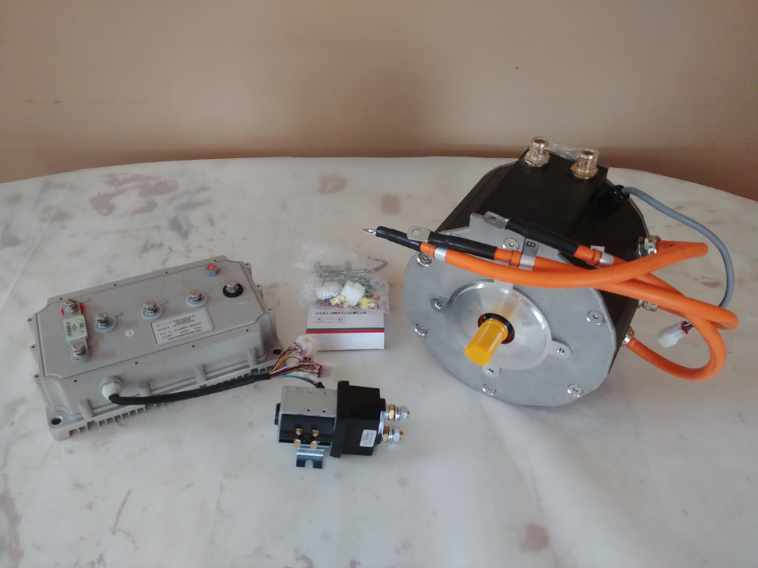
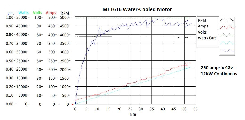
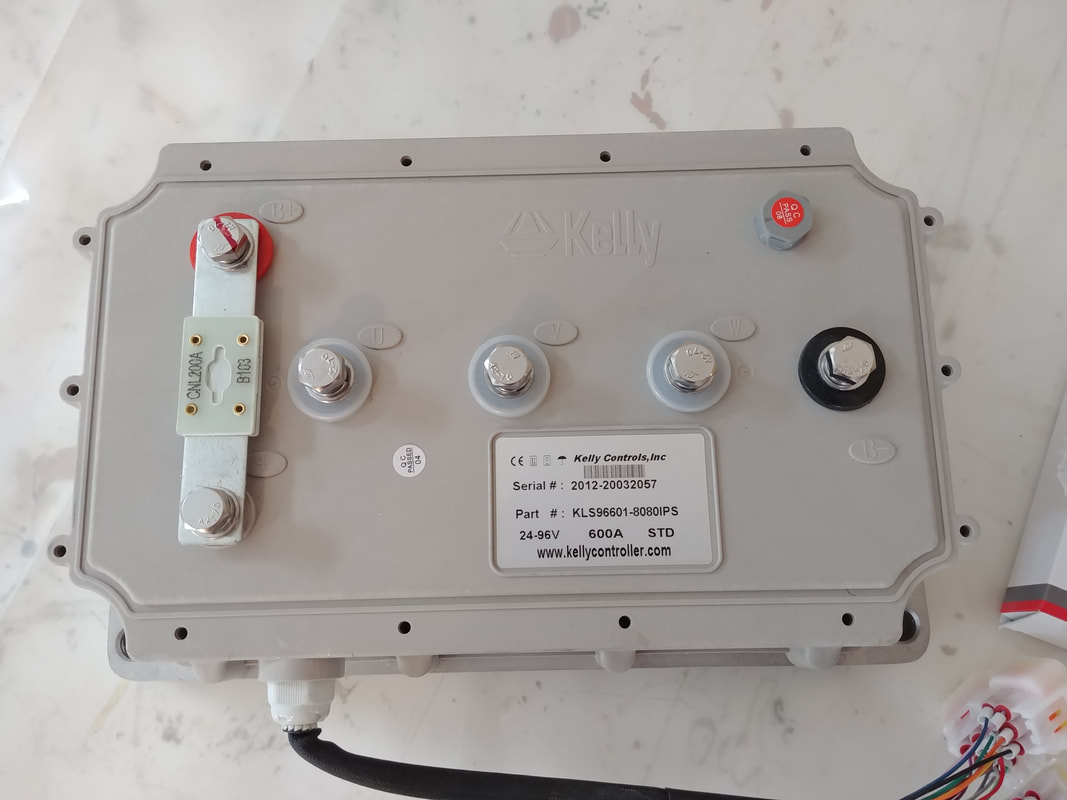
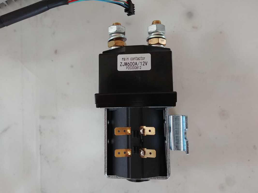
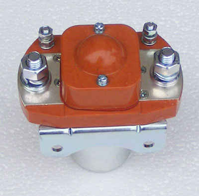
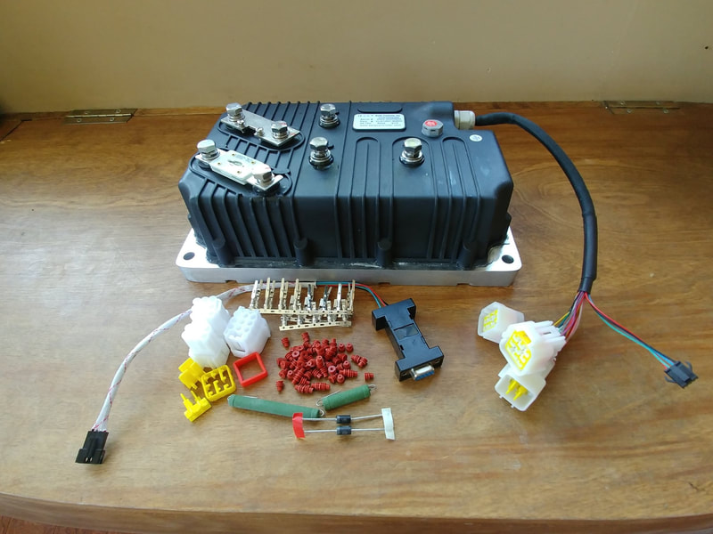
Some parts for the next EV project have arrived (I'll post pics of the model soon). Kelly Controls put this custom kit together for me, which includes a liquid cooled Motenergy ME1616 motor with a power rating of 24 kw cont/55 kw peak @ 96V (73 hp gross, see dyno chart for more power specs - will use gearing to trade some speed for torque), a KLS96601-8080IPS isolated sinusoidal wave controller, a ZJW 600A contactor and all the necessary connectors, diodes, pre-charge resistors, etc. I'll post details on the battery when the cells arrive - I'm building my own this time. If you're interested, you can contact Fany at Kelly controls for a quote for these components at sales@kellycontroller.com.
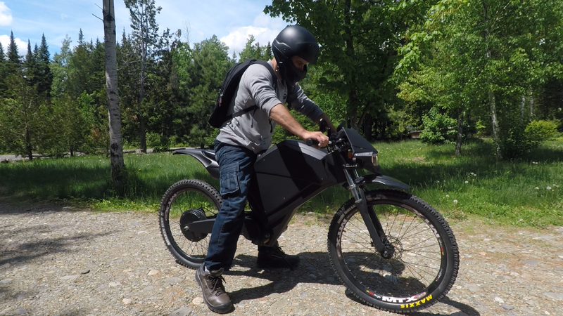
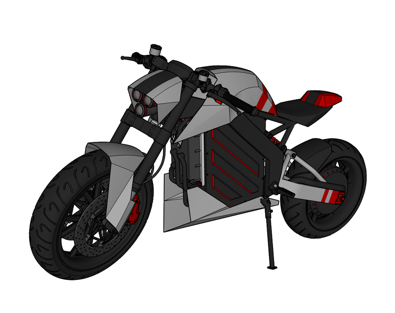
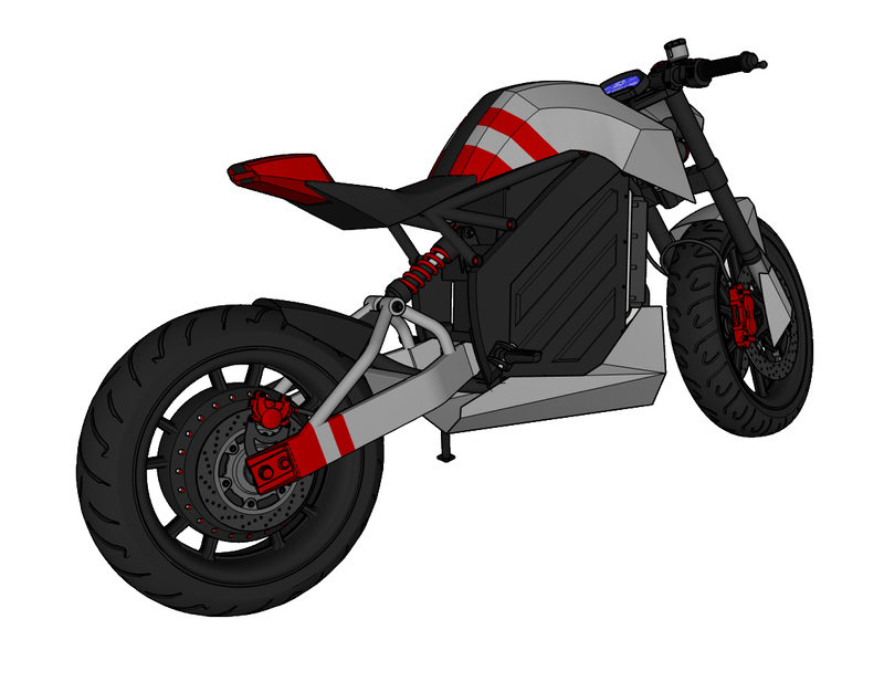
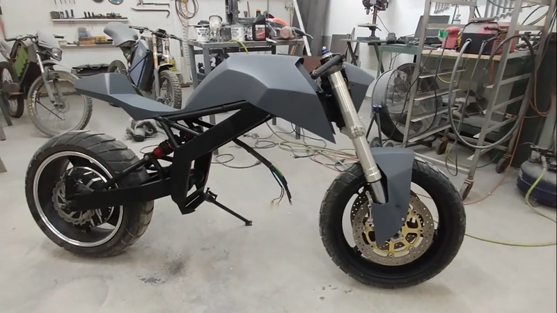
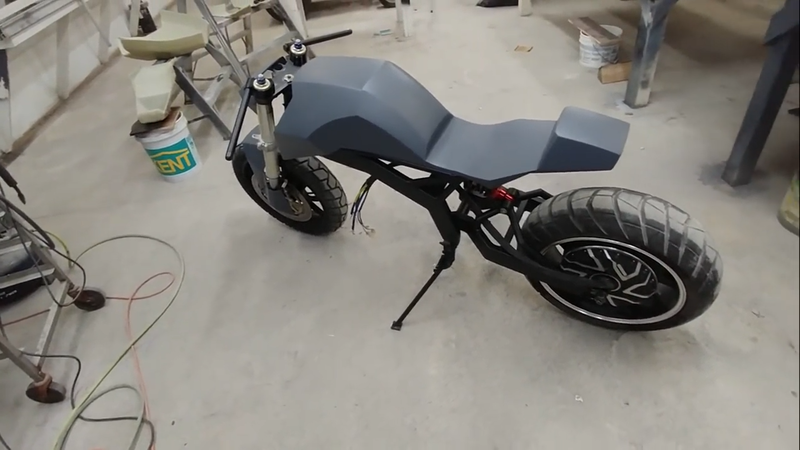
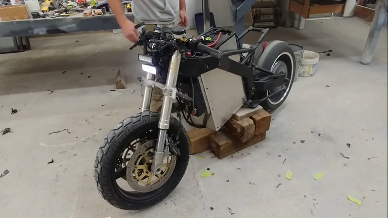
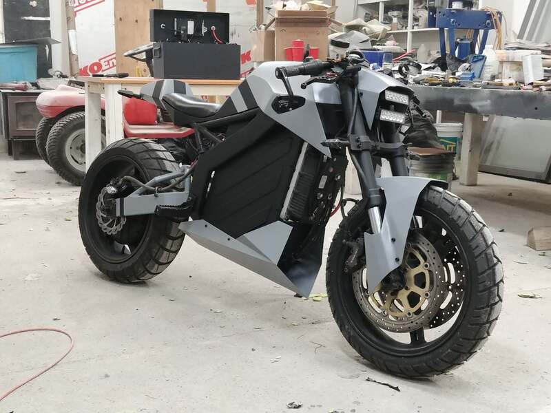
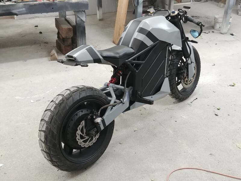
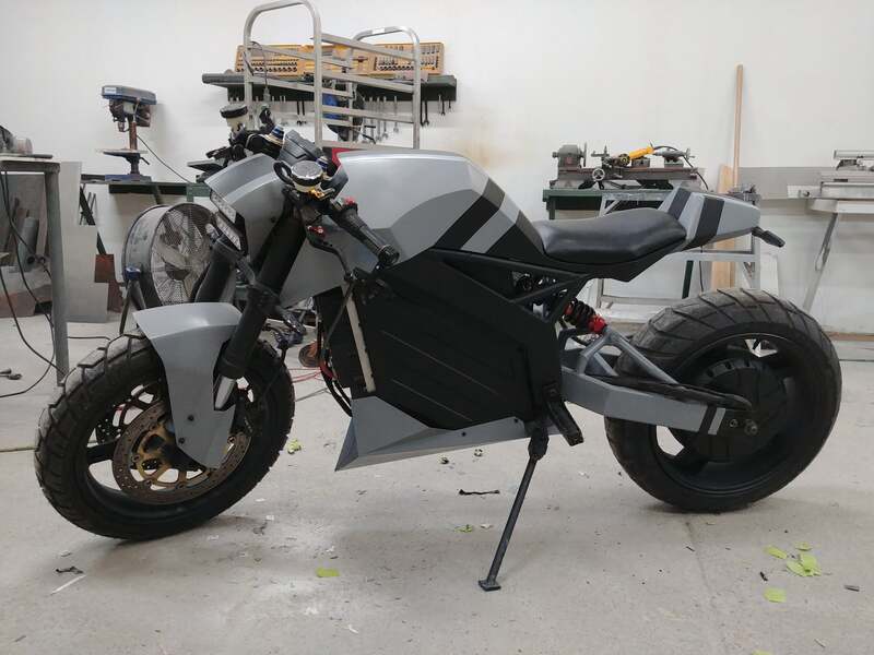
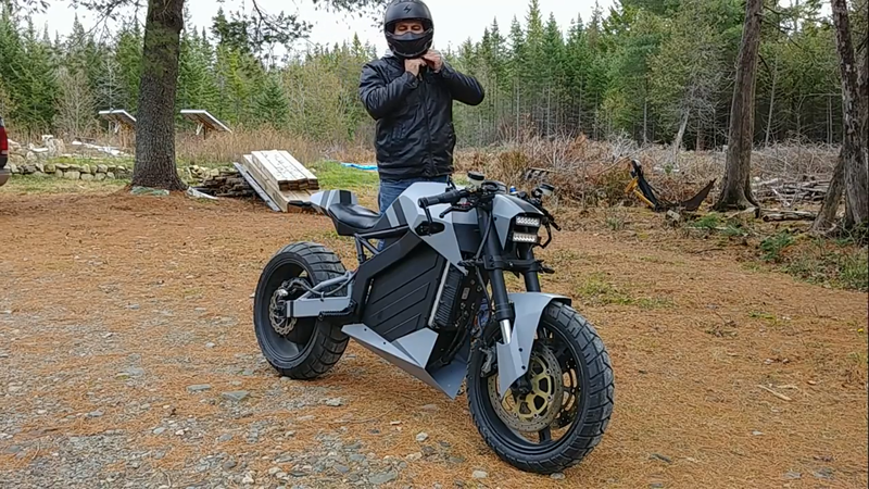
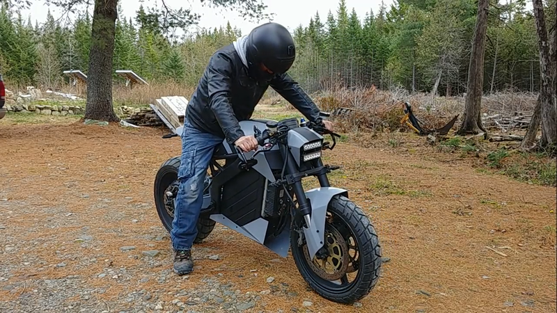
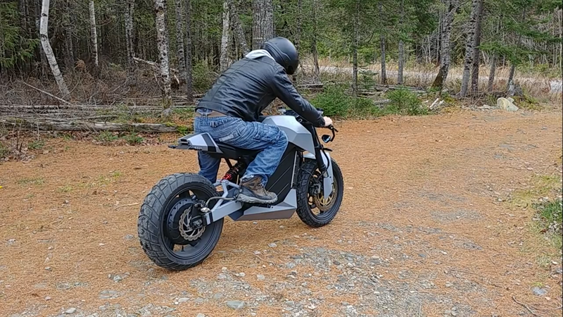
In this video I build an original custom electric motorcycle from scratch for less than HALF the price of an equally sized ZERO S (~$5000 Canadian). This aggressive looking streetfighter uses the same 24 kW (32 hp) drivetrain as the previous Cyber Trike project. Though equivalent to most 300cc street bikes in overall power, this little monster boasts a massive 250 ft-lb of max starting torque and only weighs 300 lbs. This produces a neck-snapping acceleration rate of over 8 m/s^2.
However, as force (hp or watts) = speed * torque, we can't increase the torque from a given amount of horsepower without taking from the top speed. Where the R1 lacks in torque, it makes up for with a top speed of 300 km/h (186 mph)...that's where all that extra hp goes to, and is what makes it better suited for a race track vs the street. But electric motors can generate more torque and reasonable top speed with less hp because they're much more efficient. The top speed for this electric streetfighter is 120 km/h @ 72V, and 150 km/h @ 120V, which is more than fast enough to get you a speeding ticket on any North American highway. Together with the white-knuckle torque specs, this makes for an ideal combination for a really fun street machine.
Specs:
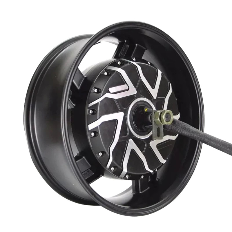
Power: 12 kw/ 24 kWp, 32 hp gross Motor: QS273 70H brushless hub motor Battery: 74V/4.3 kWh LiFePo4 Range: up to 100 km's Top speed: ~115 kph (71 mph) @ 72V, 150 kph (93 mph) @ 120V Max torque: 350 Nm (258 ft-lb) Controller: Kelly KLS72601 Wheelbase: 55" (140 cm) Rake angle: 26° Trail: 4.9" (124.5 mm) Turning radius: 72" (183 cm) Weight: 300 lb (136 kg) Front suspension travel: 5" (130 mm) Rear suspension travel: 8" (203 mm) Front tire: 120/70-17 Shinko 705 Rear tire: 180/55-17 Metzler Karoo Street
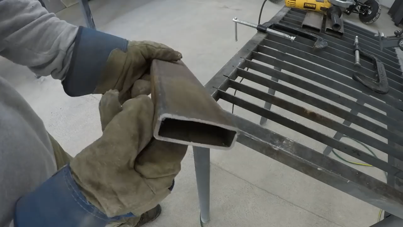
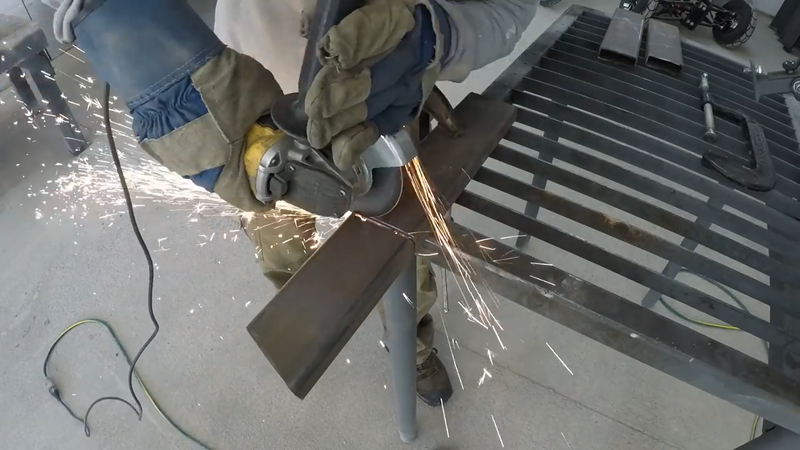
I started the build by fabricating the main frame out of 1x3x0.12" rectangular steel tubing. I didn't have a tube bender at the time, so I cut and welded mitered joints instead of bending. Where possible, I cut only three sides of the tubing and scored the fourth so that it could be bent by hand. This saves a bit of time cutting and also holds the pieces accurately in place for welding without needing complicated fixtures and clamps.
Once the pieces for each side of the main frame were cut and shaped, they were tack welded together and then the sides of the frame were temporarily connected with 1x1" crossmembers to hold them in the right position for fitting the head tube and sub frame later.
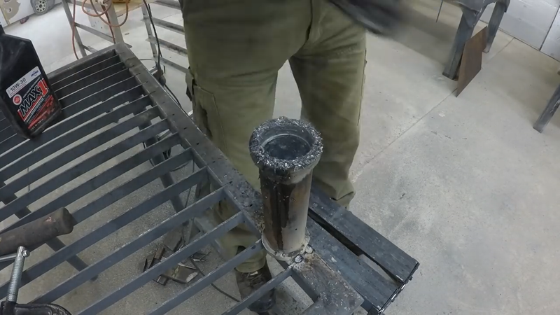
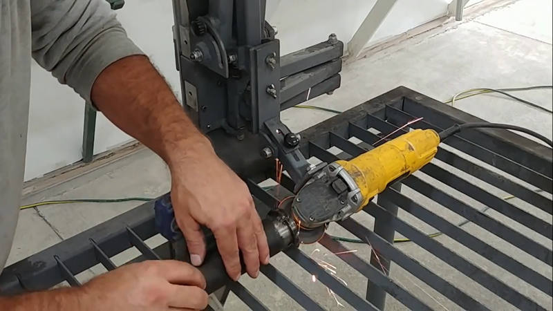
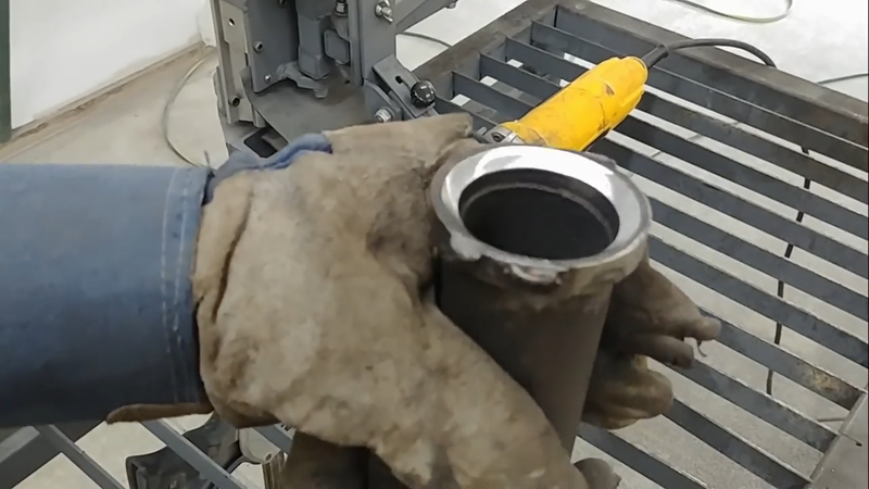
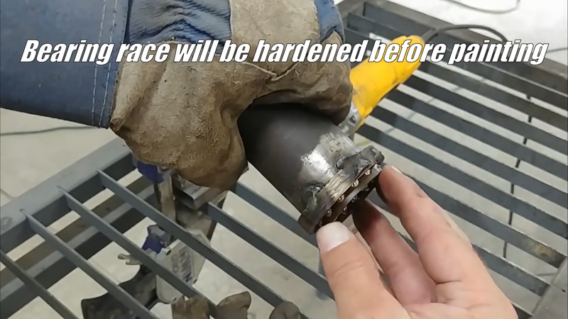
I then made the head tube from 2-1/2" DOM steel tubing. I opted to experiment with making my own bearing race cups from 3/8" high strength steel plate using a small grinding wheel on an angle grinder that's securely fixed to my modular tool guide. The DIY cups worked out pretty good after they were heat treated. However, I recommend buying replaceable race cups instead. The ones that I made will need to be removed and replaced eventually, which would be easier to do if they weren't welded in placed.
The head tube was placed onto the GSXR front forks that I chose for this build, and then I set up the main frame and forks together on a level surface to prep for connecting the head tube to the frame. The forks were set to a 26° angle from vertical to match a typical sport bike. I then connected the head tube to the frame using two pieces of trapezoidal shaped box tubing made with 1/8" mild steel plate.
Once the head tube was attached, I welded all of the joints in the main frame sequentially to avoid distorting it as the metal expanded and contracted with the heat from the welding.
Next, I cut the lower battery mounts from 3/8" mild steel plate and welded them to the frame.
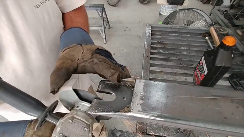
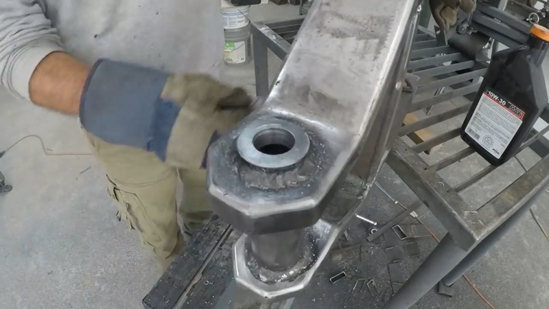
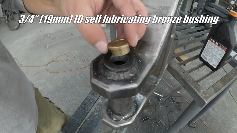
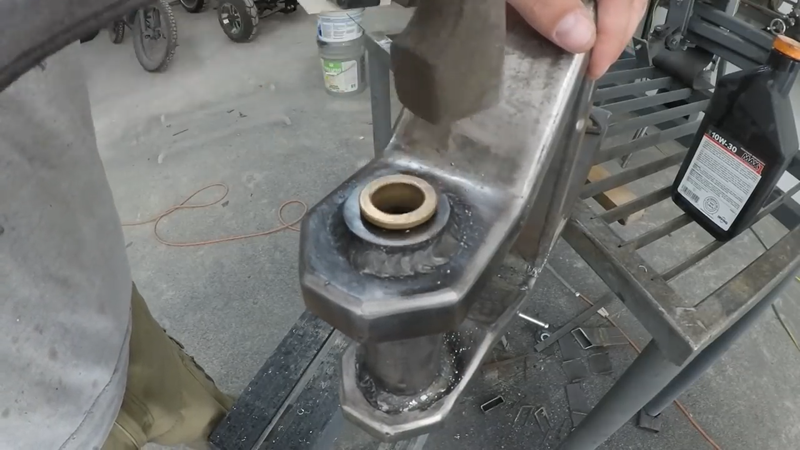
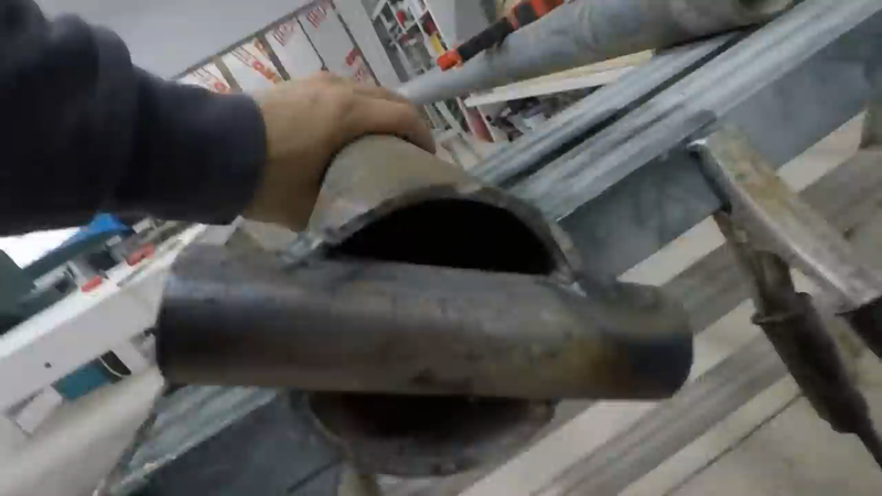
Then I made the swingarm from 1x3x0.12" steel tubing using the same mitering method that I used for the main frame. A piece of 1x3" tubing served as a crossmember to attach the two main tubes of the swingarm together at the middle, and a piece of 1-1/2" DOM tubing was welded between them at the front. The back ends of the swingarm tubing were then drilled and notched for the hub motor axle and torque arm, and the front end of the swingarm was drilled to receive 3/4" ID self lubricating bronze bushings.
I'm asked a lot why I used bushings instead of bearings, and my answer is always 'what's the difference'? A bushing is a bearing, a plain bearing, technically. Different types of bearings serve different purposes. Bushings are very strong bearings that are designed specifically for low speed, high load applications, such as on a swingarm pivot bar, or suspension linkages, and even in heavy equipment booms and boom attachments that move or rotate slowly but support a heavy load. The more popular but far more expensive ball or roller type bearings are specifically designed for high speed applications, like an axle bearing for a wheel travelling at ~1000 rpm. They generally have a lower load rating compared to bushings, however, because they're exposed to higher speeds. Of course, nothing says that you can't use a ball or roller bearing for the swingarm bar just like all the major bike manufacturers, but there's really 0 benefit to it. Both a bushing and a bearing will provide more than sufficient stability and will wear at similar rates in this application. The difference is mainly just cost, aside from the fact that the bushing will operate quieter because it's impregnated with oil to be self lubricating, which avoids the need for multiple rollers packed with grease. When you're building a custom machine on a budget, cost benefit decisions matter. When you're building a custom electric bike that has next to no engine noise, you're going to want to limit the amount of noise it makes when the suspension is travelling over bumps.
I connected the swingarm to the frame with a 3/4" stainless steel shaft, and then made the rear suspension mounting bracket for the frame and installed the rear shock absorber. I placed the shock to establish the position of its other mounting bracket on the swingarm, then cut a piece of 1-1/2" DOM tubing, capped and drilled the ends and bolted it to the 'free' end of the shock. I then cut and mitered some 1" DOM tubing and welded it as reinforcement between the swingarm and the shock mount.
After the swingarm was finished, I made the subframe for the seat using 1" DOM tubing.
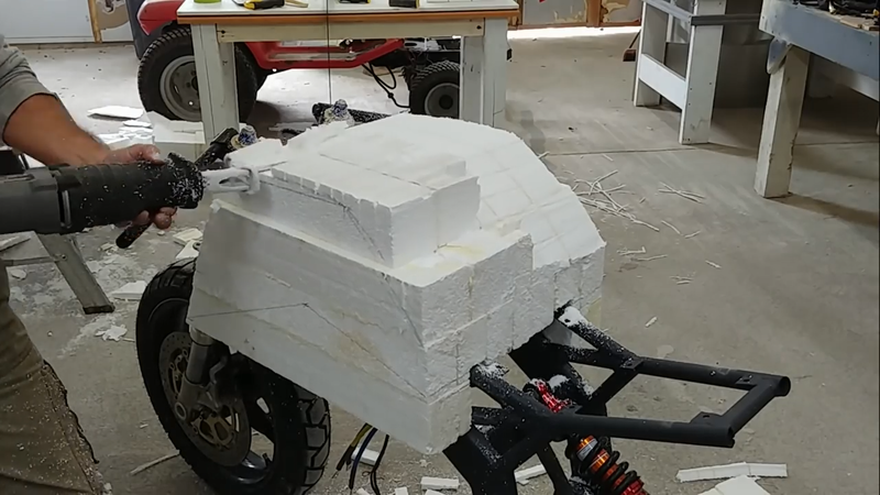
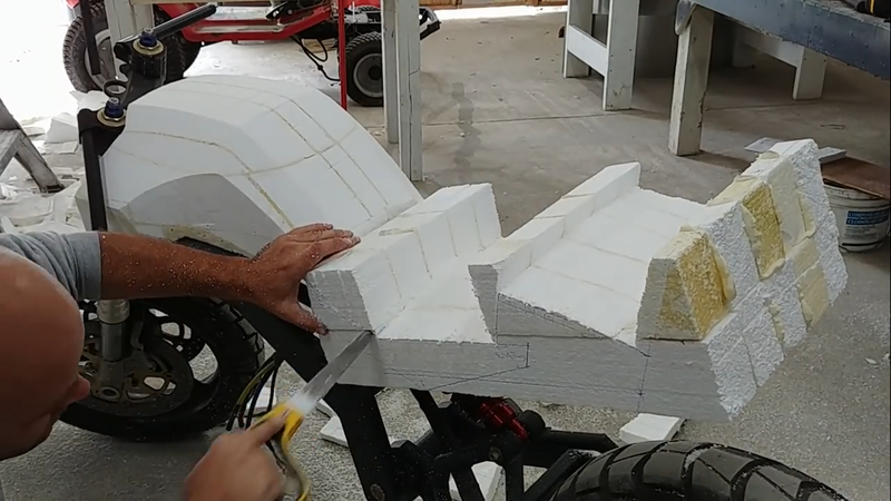
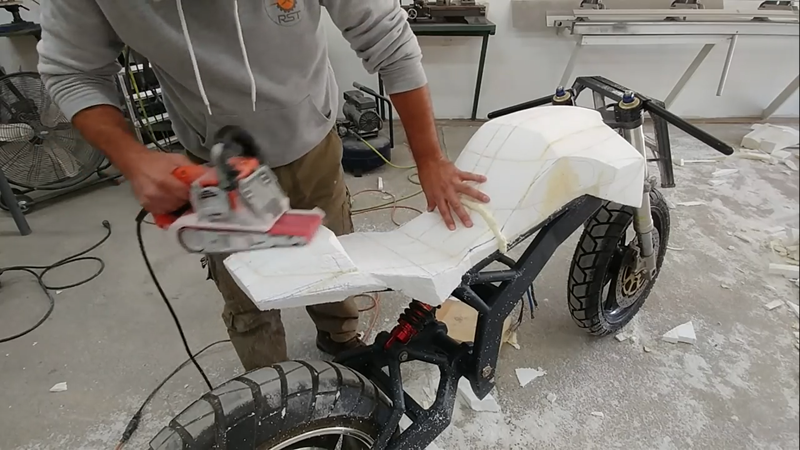
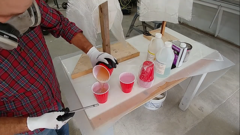
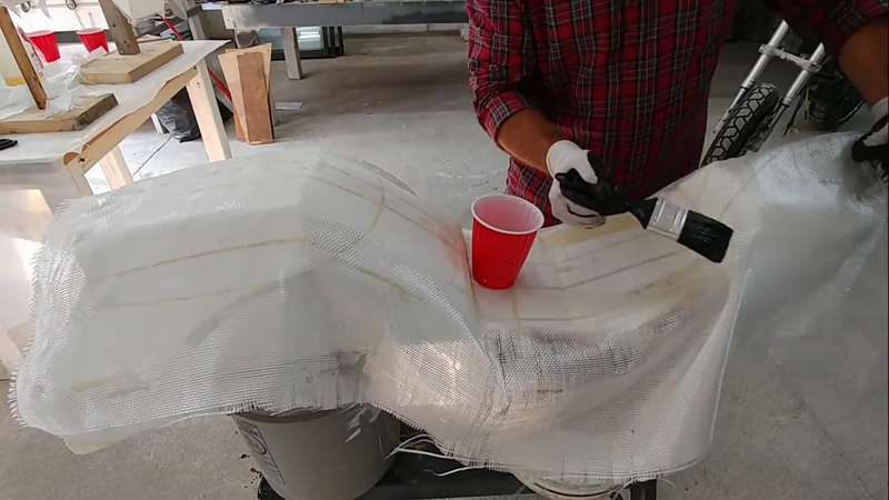
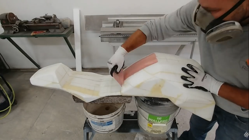
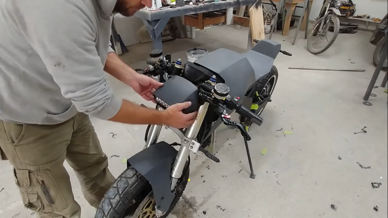
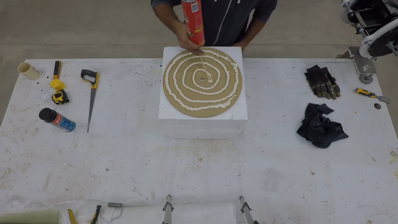
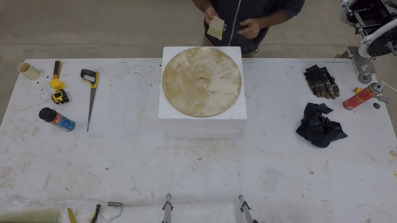
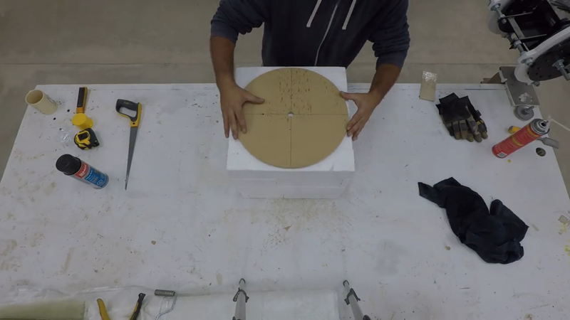
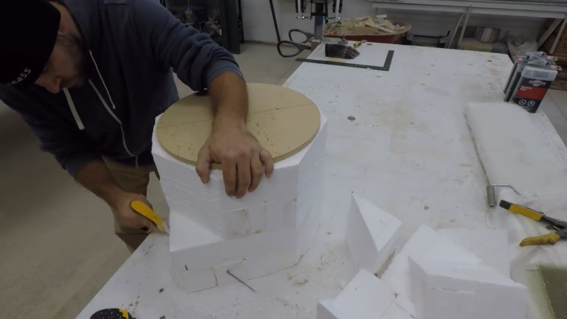
The next task was to make the fiberglass fairing. But first, I need to make a plug to make the mold to make the fairing. The fairing can be made with a 3D printer instead, but I don't own one (yet). The plug is basically just a polystyrene model of the fairing. I carved it using saws and a knife, and smoothed the surface slightly with sandpaper. Then I mixed up some laminating epoxy and brushed it onto the plug quickly before covering it with 2 layers of 10oz fiberglass cloth. It's important to point out here that epoxy was used instead of (polyurethane) resin because resin will melt polystyrene foam, which would have ruined the plug. Laminating epoxy will not damage the foam.
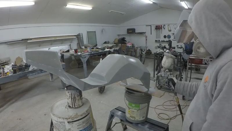
Once the epoxy had cured a day later, I sanded and smoothed the surface with epoxy filler, then painted and finished it with a lacquer finish.
I made the molds in two parts using two different materials, called 'sock and mother' molds. The 'sock' mold will be the finish mold used to cast the parts, and will be made from a flexible RTV mold silicone. The flexibility of the silicone will make demolding casts easier without damaging anything. But because the silicone sock molds are flexible, they need a strong support. This is the purpose of the 'mother' molds, which will be cast in resin and fiberglass.
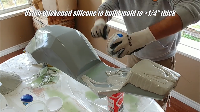
The first step was to apply a release agent to the surface of the plug. I usually just use petroleum jelly but there are commercial release agents available as well. Then I mixed up some regular RTV mold silicon and applied 2 thin coats to the plug and let it cure overnight. The next day I added a thickening agent to a new batch of silicone and applied a thick layer over the existing silicone poured onto the mold the day before. I built up the thickened layer to somewhere between 1/4-1/2" thick on the plug. Making it thicker won't hurt anything other than cost, but I recommend not making them less than 1/4" thick because large sock molds tend to get too floppy and weak if they're made too thin.
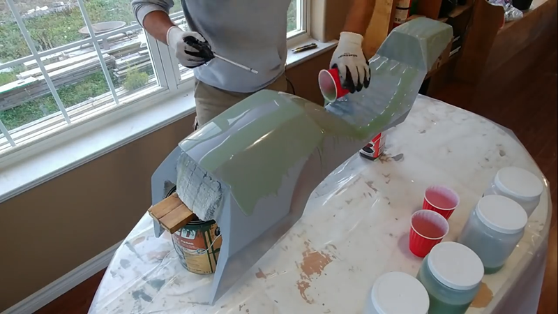
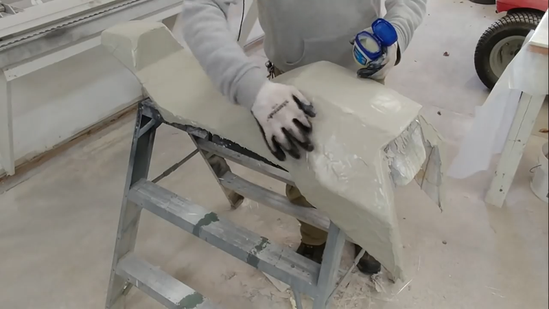
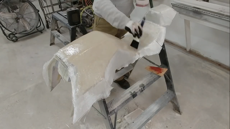
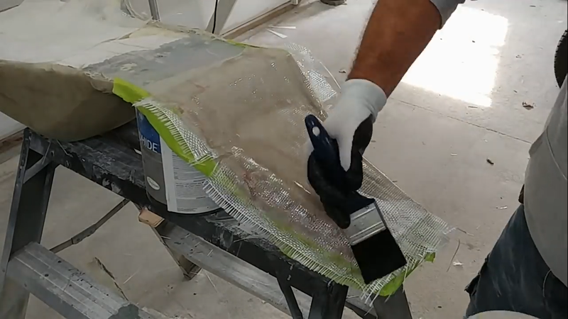
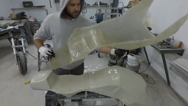
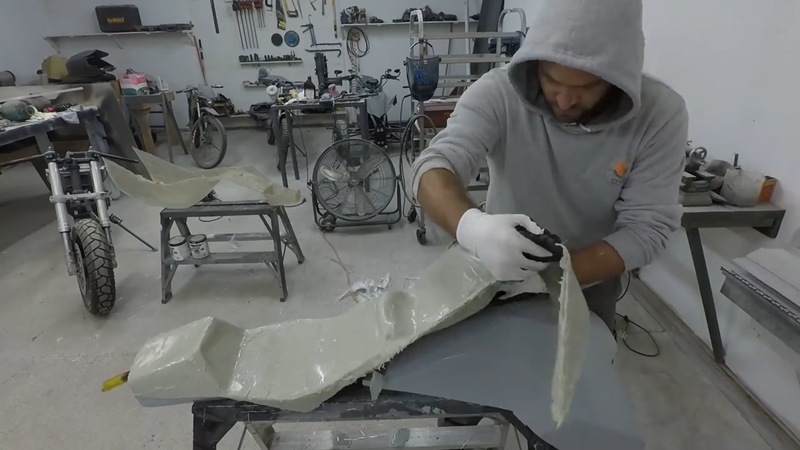
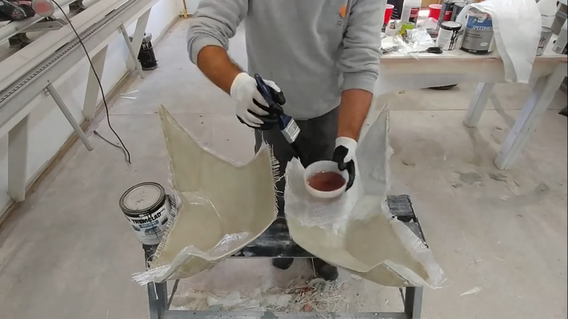
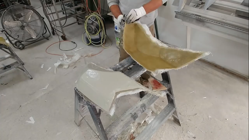
After the silicone sock molds were cured, I left them on the plugs without disturbing them, and started the mother molds by applying a layer of petroleum jelly onto the silicone, and then 4 layers of fiberglass cloth and polyester resin. I used polyester resin this time because it won't damage the silicone and it will cure much quicker than epoxy. After the fiberglass cured, I removed the molds from the plugs. The sides of the molds were quite steep, so to make casting the actual fairing parts easier and eliminate the risk of the cast collapsing on itself, I cut the molds into smaller pieces.
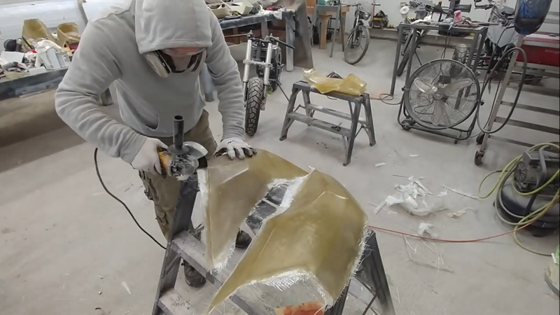
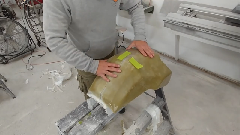
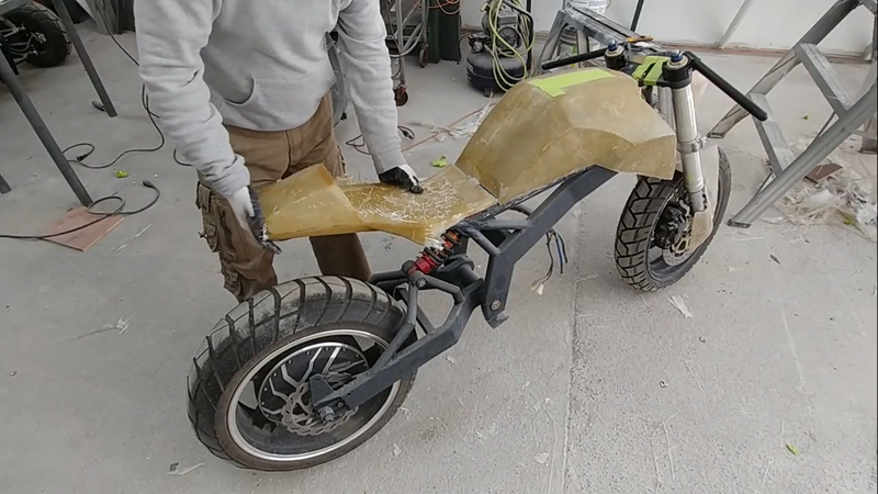
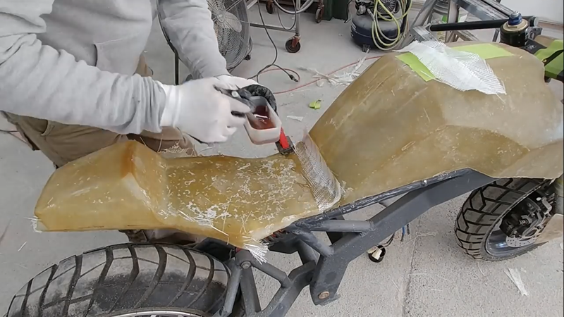
Then I applied more release agent to the sock molds inside surface and cast the fiberglass fairings. After they had cured, I demolded them, trimmed the edges with an angle grinder, and attached the fairing parts together using fiberglass strips and resin. Then I repaired any air bubbles and blemishes with polyester filler, sanded, primed and then painted them.
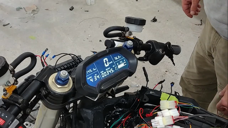
After the messy work was done, I could finally start wiring the drive system according to the schematic shown below. I used the 74V/60 ah LiPo battery that Grepow had custom built for the Cyber trike project, with a KLS72601-8080H controller from kellycontrol.com, and a QS 273-70H hub motor. I incorporated a 400A contactor to turn power on and off to the controller with a key switch, and used a 72-12VDC step down voltage converter to operate the 12V light and horn circuits.
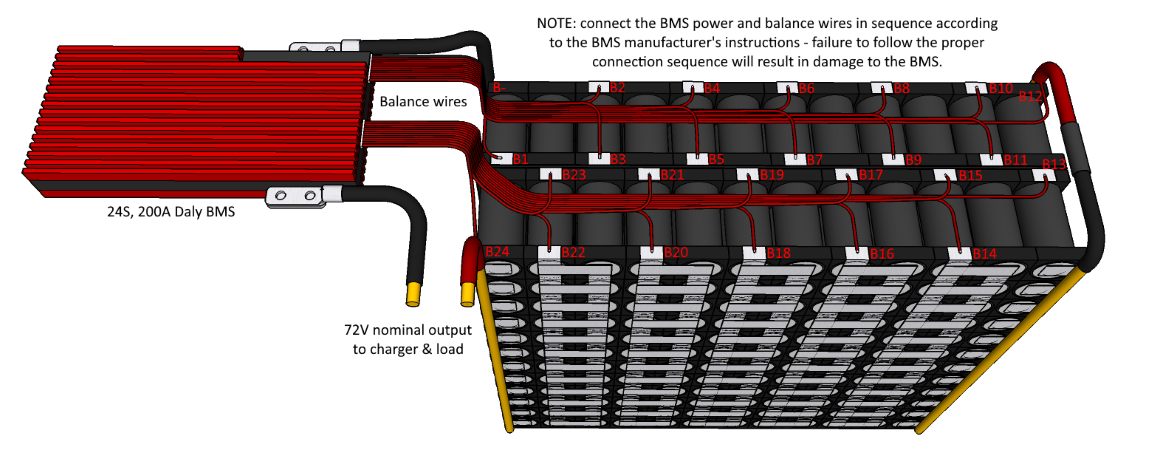
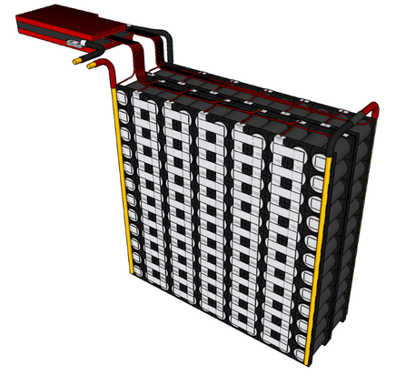
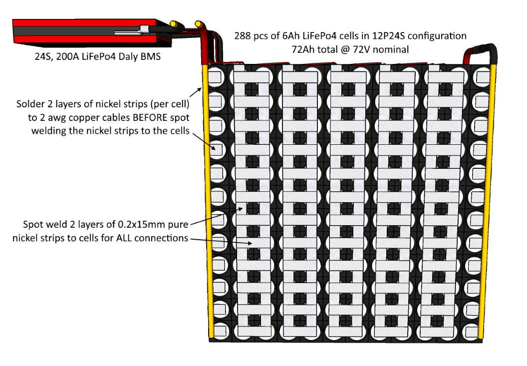
Because Grepow doesn't sell batteries directly to the general public, I recommend using 6000mAh LiFePo4 cells from batteryhookup.com to build your own battery like the one shown below that I designed to work with this bike. With a 12P24S configuration, you'll get 72Ah of capacity @ 72V, with 180A of continuous discharge current (720A peak) and a 72A (1C) max charge current (~1hr charge time with the charger listed in the BOM). A perfect match for this drive system. All of the cell to cell connections should be done with 2 layers of 0.2x15mm pure nickel strips, and the series connections between the two separate packs and the BMS should be done with 2 awg copper cable to ensure all connections can safely handle the full 180A load. Where nickel strips are connected to the copper cables, they should be soldered together first, then the nickel strips can be spot welded to the cells. If you solder after, you could risk overheating and damaging the cells with your soldering iron. This is also why you should spot weld the cell to cell connections and not solder them.
After making all the connections, I connected the controller to my PC and performed the angle identification procedure using Kelly's program (available for Android devices too). This is necessary to do in order to sync the motor with the controller. Once the procedure was finished and verified successful, I disconnected the controller form the PC and cranked the throttle to test. Everything worked fine, no problems. Time to make a seat and finish the build.
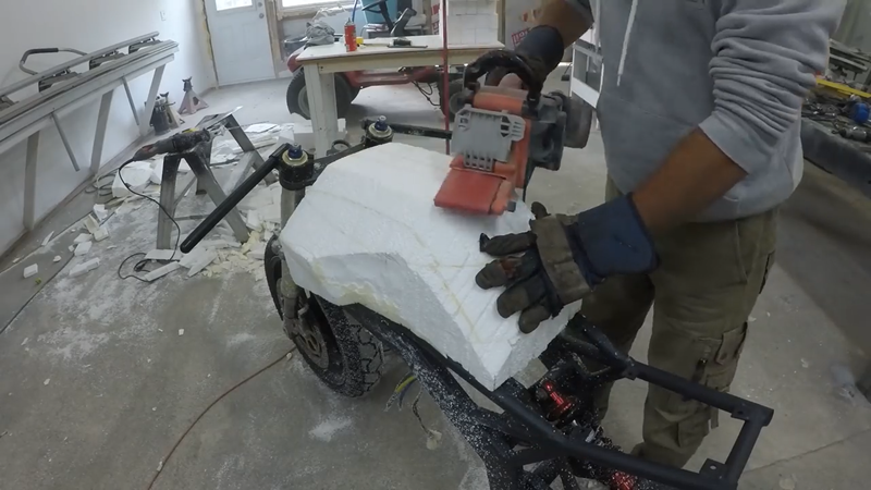
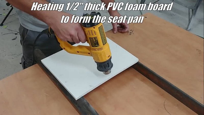
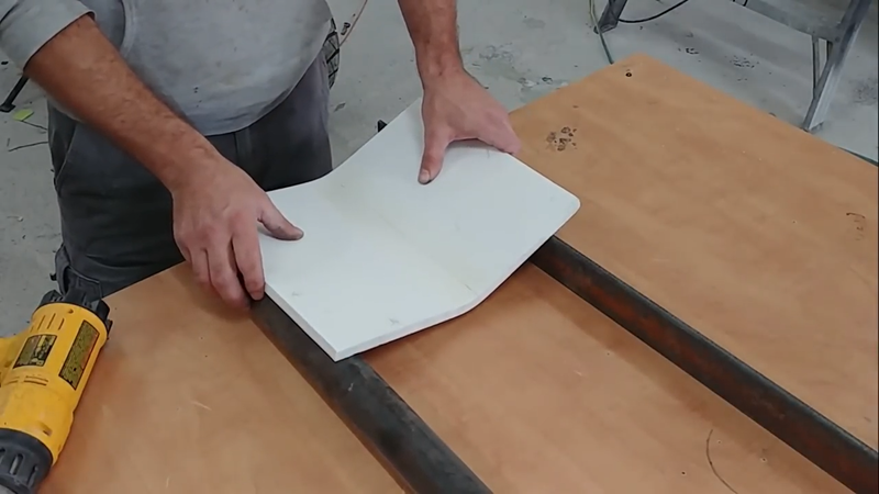
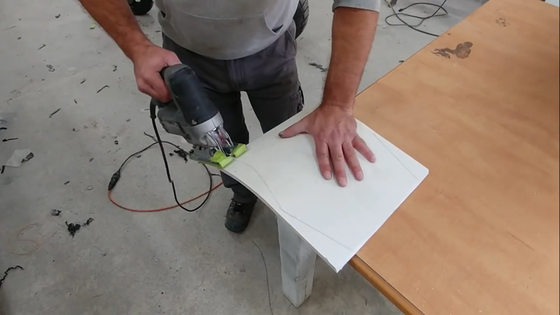
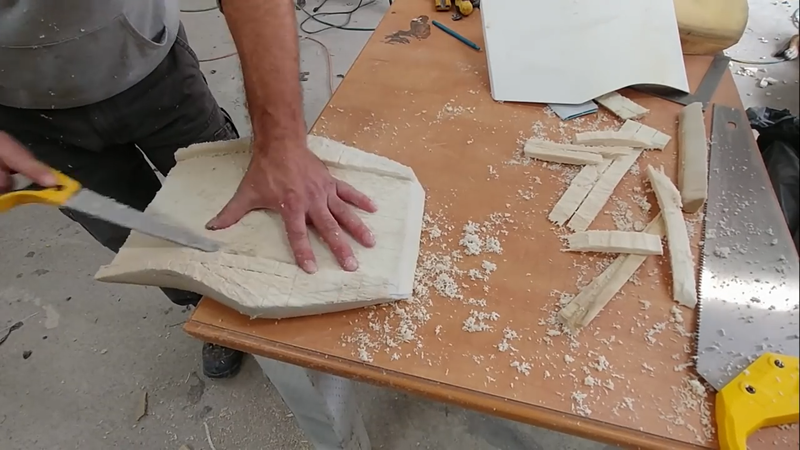
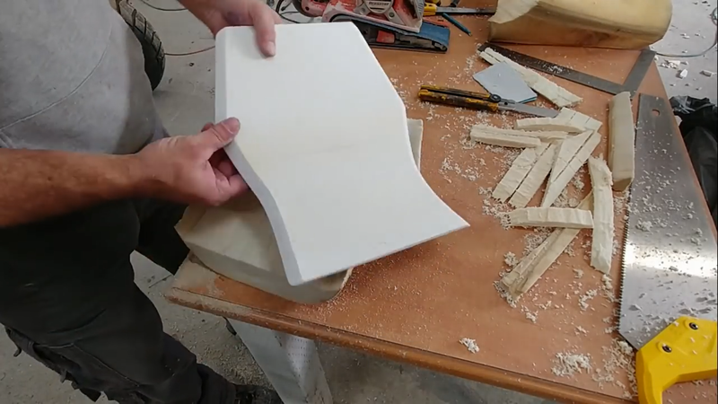
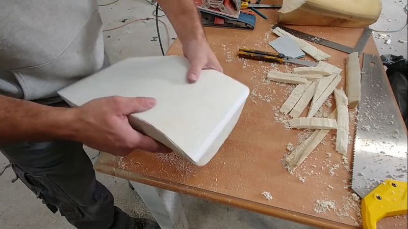
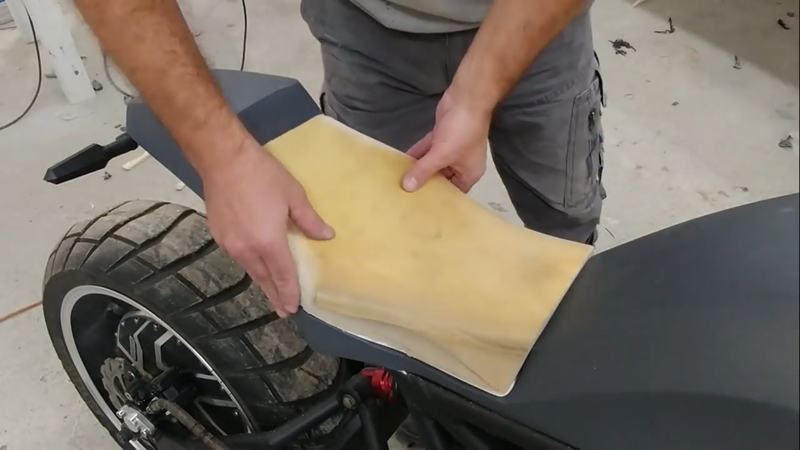
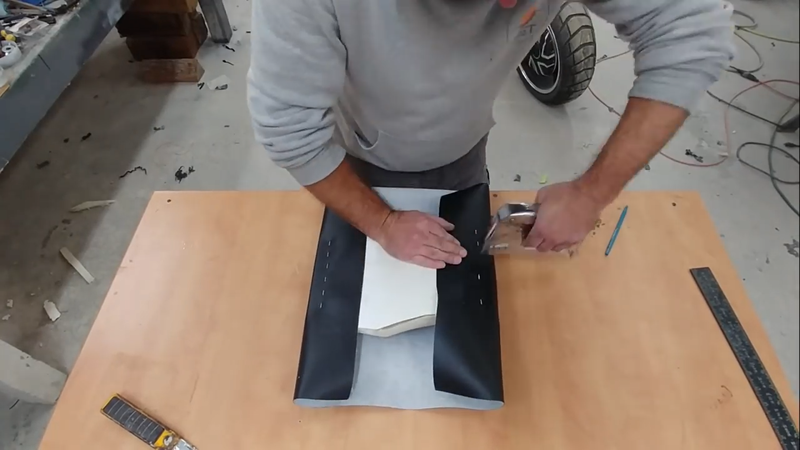
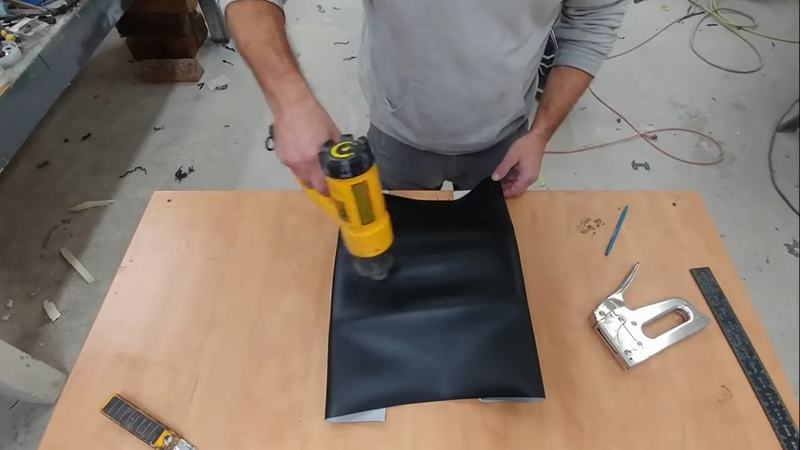
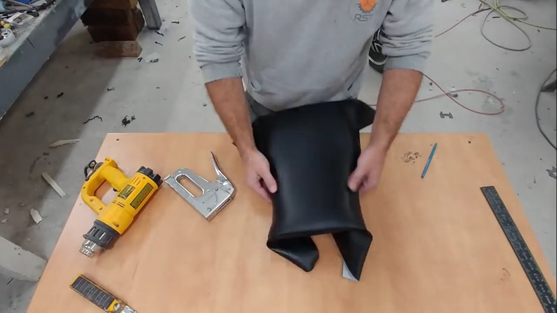
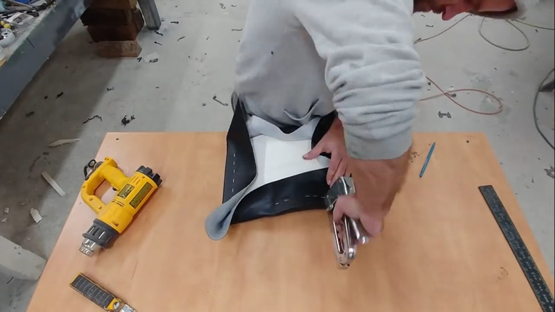
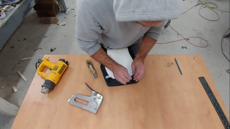
For the seat pan I used a piece of 1/2" PVC foam board. I really like this materials because it's lightweight, easy to work, and easy to fasten seat cover material to with staples, but it's also very strong. I used a heat gun to heat the PVC and shape it to the profile of the bike, then trimmed it to size. The cushion material - recycled from an old torn up ATV seat - was then shaped using handsaws and a belt sander, then I wrapped it with a vinyl seat cover. The vinyl cover is a two-way stretch material, meaning it can stretch in two directions to make wrapping around contours easier. The trick to prevent wrinkles and get the cover as tight as possible is to first fasten it to the seat pan at the front and back, then use a heat gun to heat the material in the middle where it needs to be pulled down toward the cushion. Once it's relatively warm to the touch, pull the other two unfastened sides around the seat pan tightly with equal pressure and staple them. Then work each corner, starting in the apex of the corner first and working toward the sides. There will always be wrinkles on the bottom side, but as long as they're kept small/thin then the fit will be fine.
The seat was then screwed to the fairing through the bottom, and it was time to go for a test ride! Which went well. The suspension needs some fine tuning, as to be expected, but other than that I couldn't be happier with how it turned out. For the sake of economics, I did a cost benefit analysis and posted the details below.
ROI breakdown:
Cost of electric bike build = ~$5000 total Nominal battery capacity = 4.3 kWh Life span of LiFePo4 cells = ~5000 cycles Range per charge = ~80km @ 80% DOD (up to 100 km @ 100% DOD) Local grid energy cost = $0.12/kWh Cost per charge (100 km) = 0.12 * 4.3 = $0.52 Cost per km for energy = 0.52 / 100 = $0.005 Avg price of gasoline in Canada = ~$1.00/ liter Energy in 1L of gasoline = 8.9 kWh Fuel economy of the most efficient petrol bikes = ~60 miles per gallon, or 25.5 km/L Cost per km for fuel = 1 / 25.5 = $0.04 Electric bike energy cost savings per km = $0.04 - $0.005 = $0.035 Savings per charge/cycle (80 km) = $0.035 * 80 km = $2.80 Payback period based on full cycle charges = $5000 / $2.80 = 1785 cycles OR Savings per day based on driving an avg 40 km per day as a daily commuter = $2.80 / 2 = $1.40 Payback period = $5000 / $1.40 = 3572 days, or 10 years. 5 years if driven 80 km per day.
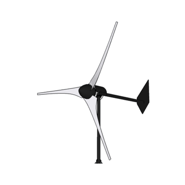
In this video I build an axial flux wind turbine with a 12 ft (3.7 m) diameter rotor driving two 12 coil/16 pole axial flux permanent magnet generators that produce up to 3 kW in a ~30 mph wind stream. In an area with a mean annual wind speed of 11 mph (5 mps) or higher, this turbine will produce 500 kWh+ of energy every month, nearly enough to take an avg home completely off the grid.
Specs:
Rotor diameter: 12ft (3.7m) Swept area: 113sq.ft (10.5sq.m) Blades: 3 @ 72", SD7032 airfoil TSR: 7 Generator: direct drive, dual rotor PMG Power: ~3 kW @ 30 mph (13.4 mps) Voltage: 12, 24, 48 VDC Cut-in speed: 5 mph (2mps) Overspeed protection: furling tail mechanism Monthly production: 500 kWh @ 11 mph (5 mps) mean wind speed
Axial flux HAWTs are among the most efficient wind turbines in use today, and the
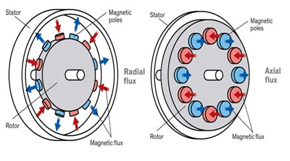
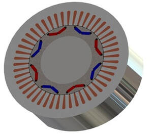
key to their well known reliability lies in the stator, or what isn’t in the stator to be more accurate. Before I get into the build details, I think it would be best to explain more about the axial flux configuration and why I'm using it. Most wind turbine generators are of the radial design, which means that the flux produced by the magnets flows perpendicular from the rotor shaft through the coils and back. The stator coils are wound around laminated steel cores which attract the flux and helps direct it across a long air gap through the coils and back to the rotor magnets again. The downside with this configuration is that the magnets mounted on the rotor shaft are naturally attracted to the steel stator coil cores, so as each magnet passes a coil, a ‘tugging’ or pulsating resistance against the rotor is created by the attraction between the magnet and the steel, commonly called ‘cogging’. Cogging has a negative effect on both start up speed and overall efficiency because it requires more wind power to overcome the resistance.
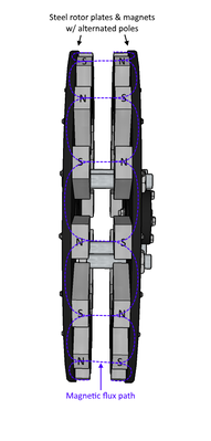
An axial flux generator is configured so that the magnet flux runs parallel to the rotor
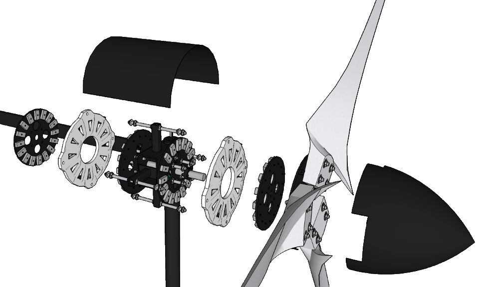
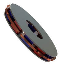
shaft. The stator is commonly referred to as an ‘air core’ stator because it contains no steel to cause the cogging effect. Instead of wrapping the coils around a steel core to direct the flux, the axial flux coils are encased in resin and the subsequent stator is mounted between to large, round steel rotor plates to which the magnets are attached on the inside faces. The steel plates move in unison and direct the magnet flux from one plate, across a much thinner air gap through the coils to the other plate and back without causing any resistance on the rotor. An axial flux generator will also have a high # of active windings and less overhang which means the coil turn count can be increased without increasing heat caused by the end effect. The other advantage to the axial flux design is that anyone motivated and with access to basic hand and power tools can build it - no expensive professional machining equipment needed!
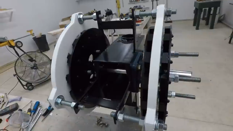
I began the turbine build by making the steel frame, specifically what's sometimes called the 'torque tube', which is the portion that the flange bearings for the rotor shaft mount to. I used scraps that I had laying around in the workshop, which resulted in using some heavy 4" A36 channel and 3/16" thick steel plate to form a 4"x6" rectangular tube - a standard rectangular tube would be a bit lighter and save a lot of work. I drilled a 3" hole through the 4" faces on one end of the tube to receive the yaw pipe, which is the top portion of the tower that the turbine will swivel on to track the wind. I then drilled an 1-1/2" hole through the 6" faces on the opposite end for the rotor shaft, approx. 6" center to center from the first set of holes. Then I drilled out the mounting bolt holes for the flange bearings, and cut a half dozen pieces of 1/8"x1" steel flat bar and welded them to the tubing to serve as the stator mounts.
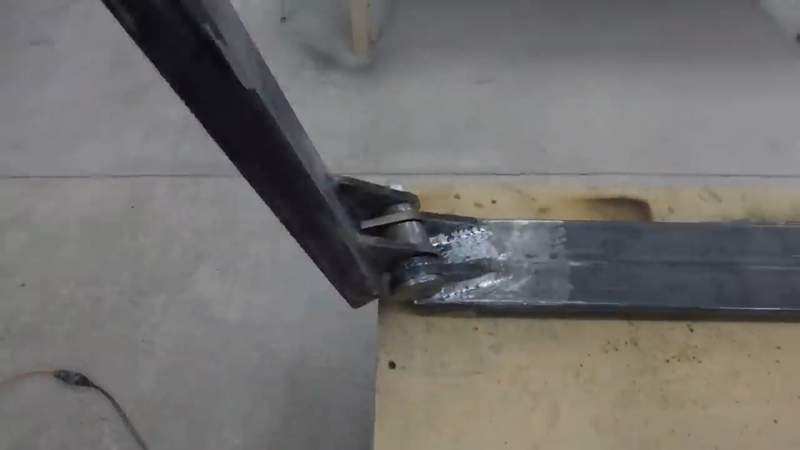
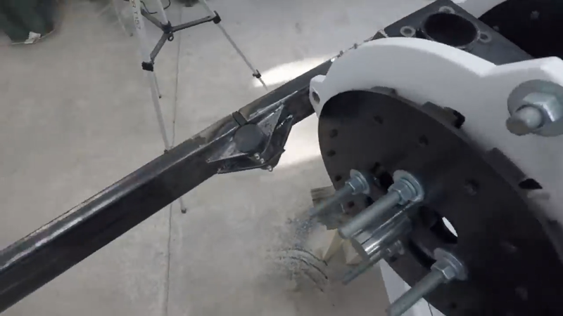
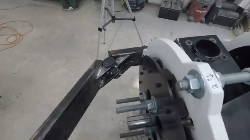
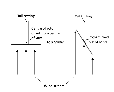
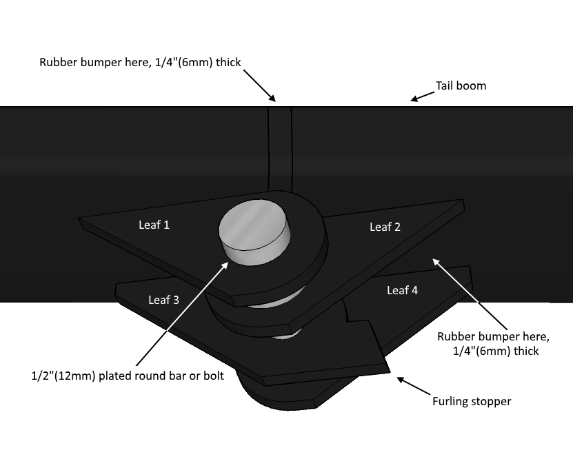
You're probably wondering why the rotor shaft is offset from the yaw. This is to accommodate the furling mechanism, which will be the mechanical automatic overspeed control for the rotor in the form of a furling tail, or 'wagging' tail as I call it because the tail boom looks like it's wagging like a dog's tail when it's operating. This happens by way of the rotor offset from the yaw and a special compound angled hinge that connects the 1"x3" tail boom to the frame, shown below.
When the wind speed reaches a certain level, the rotor being off-centered from the yaw will cause it to turn out of the wind so that the amount of swept area facing it is minimized and in turn limit (but not shut off) power output to a safe level by limiting the rpm of the blades. The angled furling tail hinge will allow the tail to remain tracking the wind but lifts it in the air during the furling process. With the rotor turned out of the wind, there's less force pushing the blades so they won't exceed a safe operating rpm. As the wind speed decreases to a safer level, gravity overcomes the wind and lowers the tail but remains tracking while the hinge forces the rotor back into the wind to optimize production again. The moment the tail lifts is what's called the furling moment, and getting it to happen at the right wind speed requires a certain offset, hinge angles, tail length, vane size, weight, etc. These are all detailed in the plans for this project.
I made the furling hinge a bit more complicated than it needed to be; the bearings can be replaced with a few 1/8" thick flat bronze washers set between the leaves. Simple and cheap. One of the leaves has a stub on the end that serves as a stopper for the tail to keep it from swinging too far. I also fastened a piece of rubber form an old tire in the joint behind the hinge to keep the tail boom from smashing into metal every time it swings. Once the hinge was made and the tail boom was installed, I tested the swing to make sure the tail vane wasn't going to hit the blades when they're installed later.
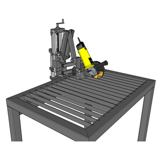
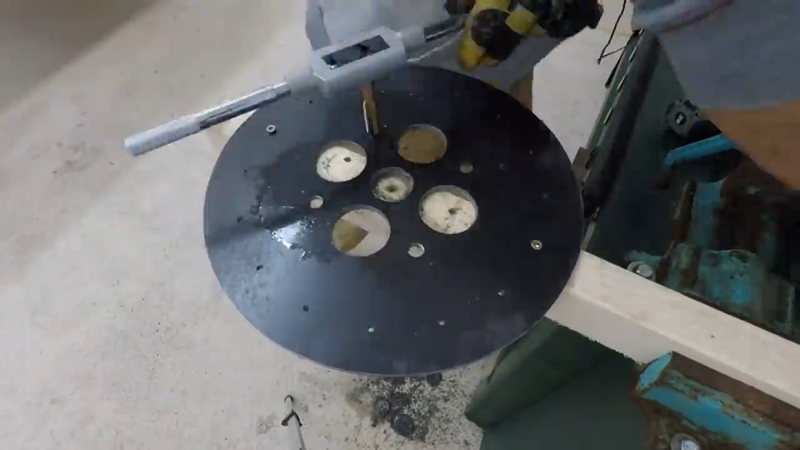
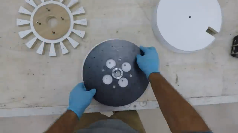
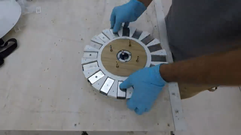
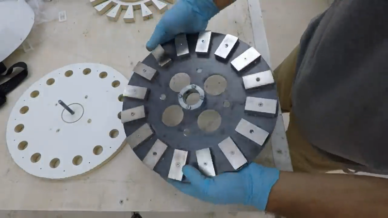
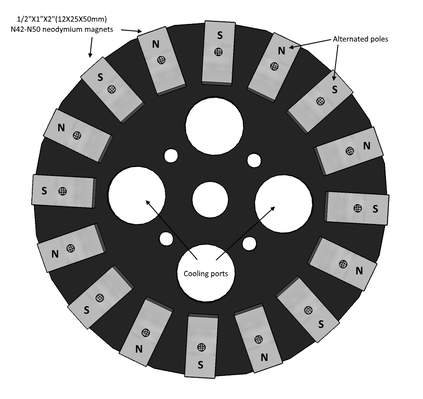
Next, I tackled the generator. I used my DIY modular tool guide to cut the magnet rotors and blade hub from 1/4" thick steel plate with an angle grinder. With the angle grinder on the guide, I can cut perfect circles of almost any size without needing a lathe or CNC. Once the plates were cut, I drilled out the mounting bolt holes for the 1x2x1/2" N45 neodymium magnets, as well as threaded the mounting/jacking bolt holes for the rotors themselves, and some large cooling ports to help the generator shed heat better when it's working in high winds.
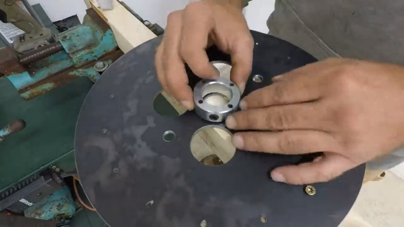
I drilled and bolted a 1-1/4" shaft collar to each plate to serve as a hub for connecting them to the rotor shaft with set screws.
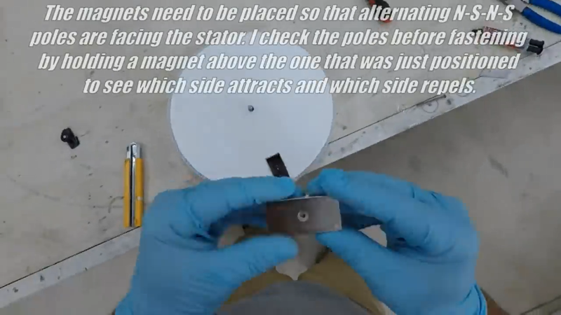
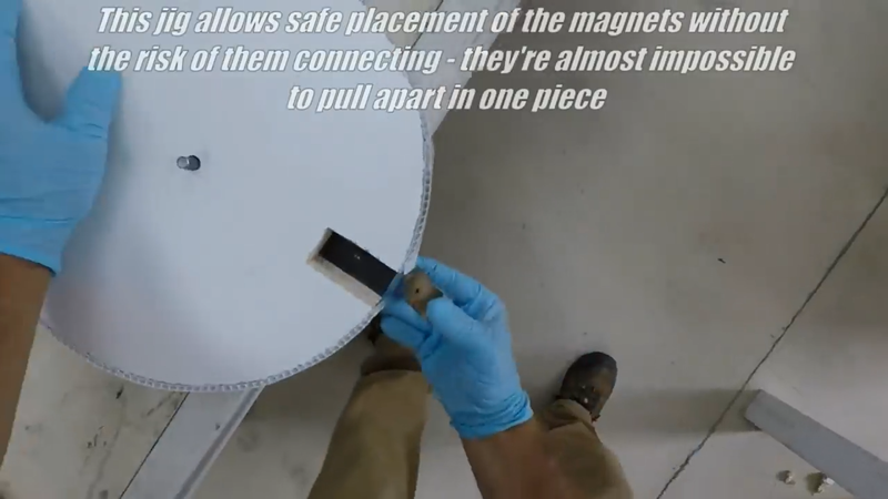
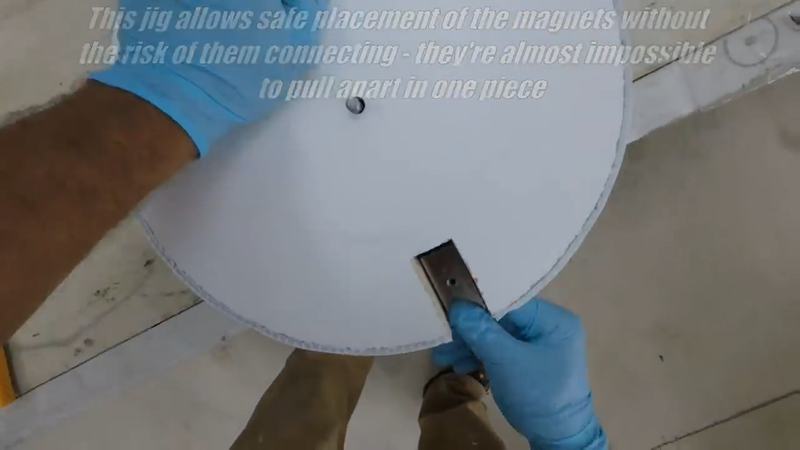
Then I installed the 1"x2"x1/2" neodymium magnets using JB weld, #8 machine screws & lock nuts, and a wooden jig that I made to hold the magnets in place as I'm securing them - they're extremely strong (~80 lbs of pulling strength each) so I had to be careful not to get them too close to each other or get my hands or fingers pinched. That pulling power also means that if the rotor plates are placed too close together before they're mounted to the shaft properly, then separating them will be like trying to lift a pickup truck. You don't want a hand or finger getting caught between them if that happens, because you'll probably lose it.
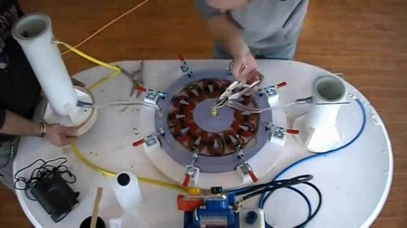
To carry the flux across the air gap between each rotor plate when the generator is assembled, the magnet pole faces need to be alternated on each plate. Opposites attract when it comes to magnetism, so all I had to do was fasten one magnet in place, then carefully held another magnet tightly in my hand and hovered it over the first magnet to see which faces were attracted to each other, then placed the next magnet with the opposite pole (attracting face) face up on the plate, and so on with all of the remaining magnets. Once one plate was covered in magnets, I started the second plate (for the first generator) with the opposite pole face up compared to the first magnet on the first plate. This is because the poles facing each other on each plate need to be alternated when they're installed onto the rotor shaft too, as shown below.
After the first pair of plates were finished, I made another pair to match then cleaned them all with rubbing alcohol and primed and painted them, then set them in a safe place FAR from each other until they were ready to install.
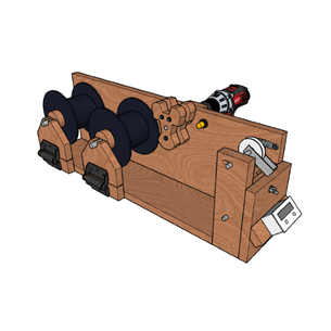
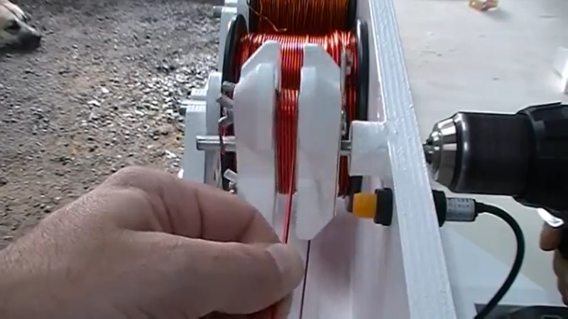
Next, I got started on winding some coils. I used my DIY drill operated coil winder to do the job. A certain winding turn count is required for different system voltages so that a turbine will cut-in (ie begin charging) at a reasonable speed. For this particular turbine, to get a 5 mph cut-in speed with a 12V system a person will need to wind 40 turns of double parallel strand wire in each coil, for 24V they would need 80 turns of double parallel strand, and for 48V they would need 100 turns of single strand - all using 14 awg wire. Double parallel strand means winding two wires together at the same time, and connecting the ends so they act as one large wire. This is needed for the lower voltage systems because they will need to carry more current (amps) in order to generate the same power as higher voltage systems (watts = volts * amps).
Ideally, the inside perimeter/shape of the coil should be the same as the magnets being used, but some compromise for the sake of space won't have much affect on performance. I wanted to minimize the footprint of the generator, so I chose the wedge shaped coils instead of rectangular coils so that I could fit them into a tighter radius. The outer edge and length of the inside profile of the coil is still the same as the magnet dimensions, the inside edge is just narrowed. When building a custom turbine for the first time, it's a good idea to wind a couple of coils before building the mag rotor plates, and lay them out on a flat surface as they would be in the stator to test how they would fit in relation to the magnets on the rotors; the magnets need to line up with the center of the coils to limit flux loss.
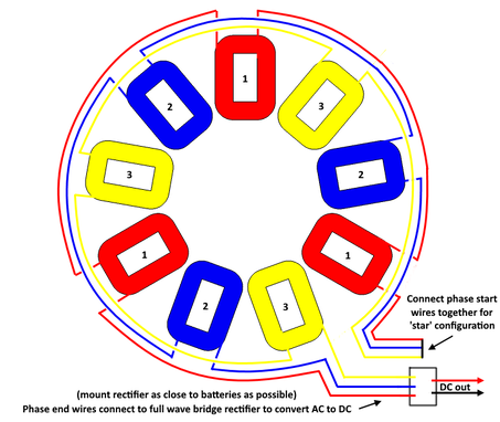
After I wound all the coils and taped them up with electrical tape to keep them as tight as possible, I soldered them together in a 3 phase star configuration as shown below.
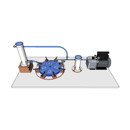
I then checked the continuity of each phase with a multimeter set to 'ohms' to make sure the connections were fine, resistance was low and that current would flow. Then I taped all of the loose wires and coils together, and prepped my DIY vacuum injection mold for casting the stator.
I applied a layer of petroleum jelly on all of the mold surfaces, then cut two pieces of fiberglass mat to place on the top and bottom of the coils when casting to add reinforcement to the stators. I used casting epoxy to cast these stators, but I prefer using UV stabilized polyester resin because it cures faster. After both stators were cured, I gave them a quick sanding and then primed and painted them. Vacuum injection isn't necessary for this, though. A person can make a simple wooden mold for the stator and pour the resin by hand. A few air bubbles are likely to get trapped in the cast, but they'll have no effect on performance or longevity.
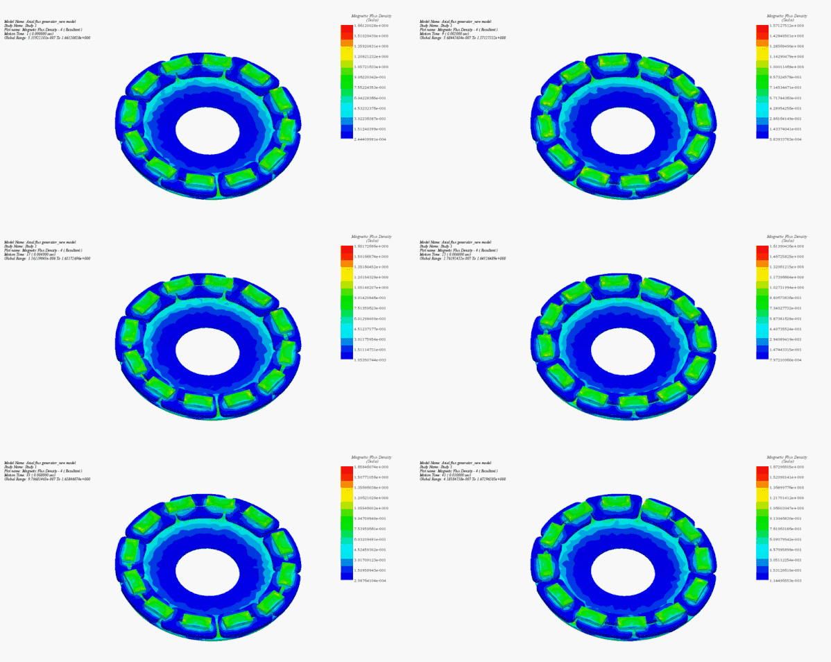
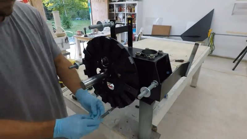
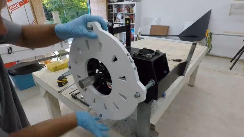
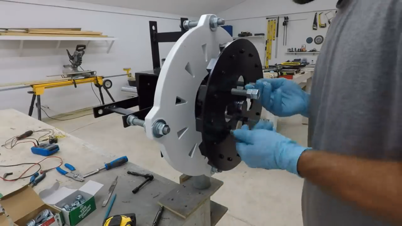
The next task was to assemble the generator. This is the nerve wracking part because the magnet rotor plates need to be jacked together without pinching fingers. I started by installing the inside rotor plate onto the front of the rotor shaft, then threaded the stator bolts onto the stator mounts and installed the stator. I used nuts and washers behind the stator to adjust it as close to the inside rotor as possible without them rubbing together. Because the magnetic flux needs to travel from plate to plate, the closer they're together the more flux that can be focused into the stator and the more power it will produce. The 'air gap' between the rotors should be as thin as possible.
Once the stator was set, I installed 6" long jacking bolts into the threaded holes in the second rotor plate with the majority of the bolts' length protruding on the inner side of the rotor plate to keep it as far as possible from the generator assembly when I start jacking them together to close the air gap. Two hex nuts locked together on one end of the rods will serve as heads, like on a bolt. I placed the protruding ends of the roads against the inside rotor plate that was previously mounted on the shaft, making sure that I have the poles lined up properly, and then started slowly jacking the outer plate toward the stator by turning each rod a few turns at a time until the outer rotor plate was within ~1/8" of the same distance from the stator as the inner rotor plate. Then I lined the jacking bolts up with the threaded bolt holes in the inside rotor plate and threaded the jacking bolts into them, then locked them together with hex nuts and secured the rotor plates to the rotor shaft with set screws in the collars. Rinse repeat for the PMG on the back side of the turbine. After both PMG's were assembled, I connected each to their own 3 phase full wave bridge rectifier, and then connected the DC output from the rectifiers in parallel and checked the voltage output/rpm of the generators with a multimeter and digital tachometer to verify they'll cut-in at the speed that I want.
The generator assembly went well, so I immediately moved on to carving a set of blades from laminated spruce.
Most micro turbine blades are made of either solid fiberglass, fiberglass w/ a foam core, plastic, or metal. Industrial turbines use a combination of fiberglass and wood. This is my preferred method, as well, but using more wood and less fiberglass. A solid fiberglass blade is easy to manufacture, but they're a bit too rigid which lowers efficiency. Plastic blades are easy to manufacture and easier to recycle, but they don't last as long as fiberglass (ie, reinforced plastic). Fiberglass w/ a foam core decreases the amount of fiberglass needed and helps make the blade semi-flexible, which would be more efficient than a rigid blade. But separating the fiberglass from the foam core to recycle either or both without involving chemicals can be a bit of a problem. Steel is strong and flexible, but is heavy and decreases the rotor's response time and efficiency as a result. Aluminum is light and strong but too rigid. It won't flex like steel without bending permanently and cracking or worse, which also decreases efficiency compared to semi-flexible blades. The best method for micro wind turbine blades, imho, is the same method that small aircraft propeller manufacturers like Culver Props still use today, which is a carved wooden blade with a few layers of fiberglass cloth covering them for protection and added reinforcement. This is a time proven method that makes blades that will last decades, using minimal plastic components and a renewable, abundant and readily available natural material that is much easier to recycle and repurpose after it's done its job. The only difference with my blades is that I use softwood to keep them as light and flexible as possible, where plane props deal with higher loads and are usually made of stiffer hardwoods as a result. All that's required to recycle them is a lathe duplicator to strip the fiberglass layers from the old blade to expose the wood. The wood can then be repurposed into a new blade if it's still structurally sound, or it can be mulched up and composted while the fiberglass dust/debris can be mixed with polyester resin to make a polyester filler.
I don't just use any old stick of softwood, though. The lumber needs to have a relatively straight grain, no checks or wanes, and ideally it should have no knots for consistent strength and flexibility throughout the blade, but if knots are unavoidable then they should be small and secure in the wood. Questionable knots can be stabilized with resin before they're worked.
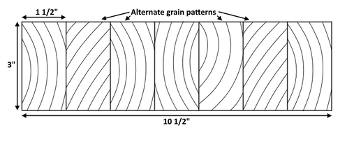
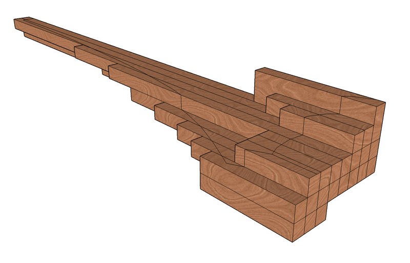
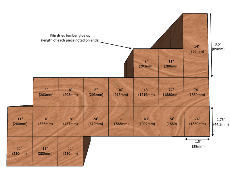
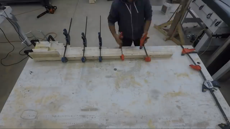
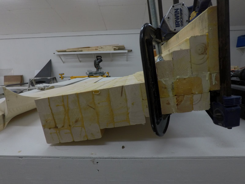
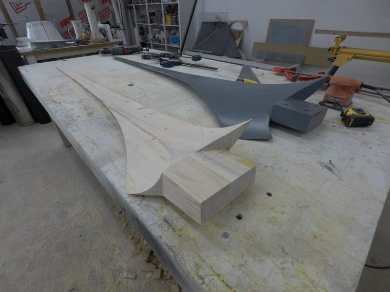
After I've chosen the wood that I want to use, I rip up the planks into narrow strips, usually 1-1/2" wide. Then I rearrange the strips so that the grain pattern is alternated in each piece and glue and clamp them back together into the blank that will be carved, like how a kitchen cutting board is made (see image above). This helps to even out any cupping or twisting that could otherwise happen if the grain was left in its natural state. This is important not only to maintain the angle of attack of the blade that will carved out of it, but also to keep the blades lined up on the rotor plane and balanced properly. It also helps to limit the waste from carving the blade because I can cut the narrow strips to almost exactly the length they need to be, as shown below.
After the glue had dried, I drew the outline of the blade profile onto the laminated block and cut it out with a circular saw and a reciprocator.
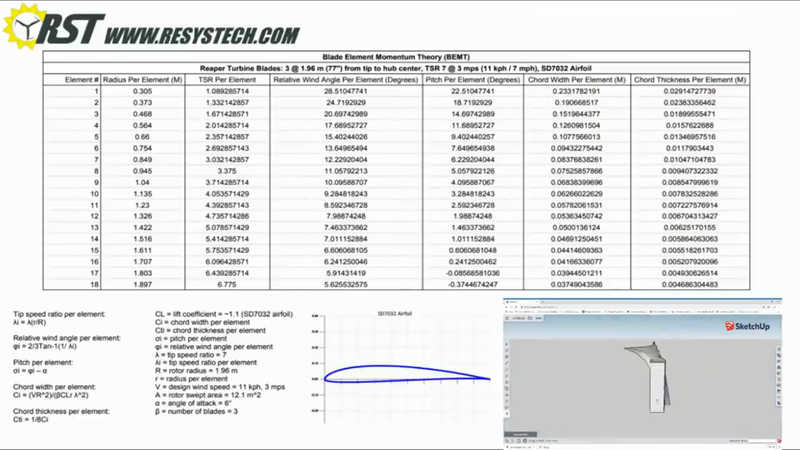
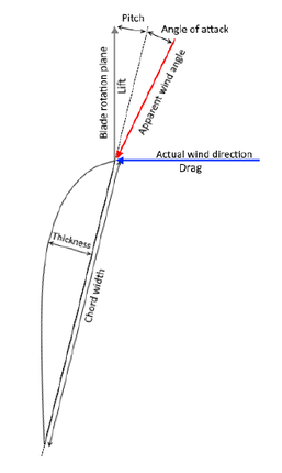
To make the blades perform as efficiently as possible, they need to be able to produce lift efficiently. This is done by using an airfoil and dividing the blade into different stations or elements along its length so that the blade's pitch, chord width and thickness can be adjusted according to the relative wind angle in that location in order to maintain the blade's angle of attack, and to optimize torque at the root section and speed at the tip. This design method is called blade element momentum theory. Of course, a person could hack away at a PVC pipe, bolt the pieces to a hub and watch it spin, but the result in power will be a fraction of what's possible with proper design. If you'd like to learn more about how to use BEMT to design your own blades from scratch, check out my turbine design guide.
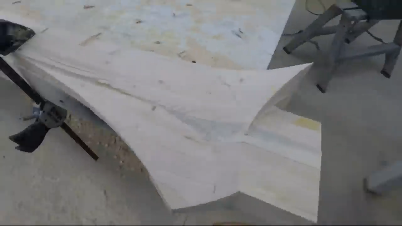
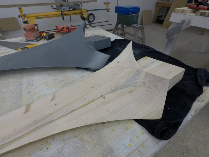
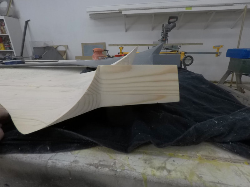
Once I had the blade's profile cut out, I used the data shown in the image gallery above that I had generated with my blade design worksheet, and laid out the stations along the blade and marked the drop for the trailing edge at the bottom edge of the laminated blank. The leading edge is represented by the top edge of the blank. The drop is the distance the trailing edge drops below the top surface of the blank, representing the front of the blade. You'll notice from the images below that the drop is different at each station. This is because the relative wind angle is different at each station, so the pitch of the blade will be different at each station to compensate, which results in a twist in the blade called a washout.
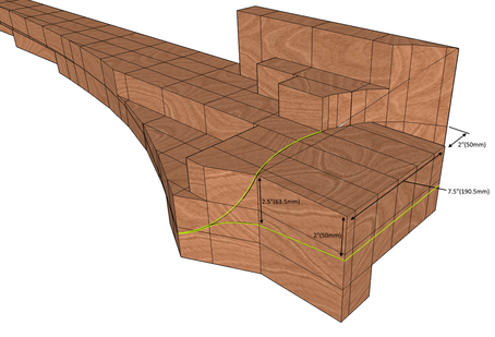
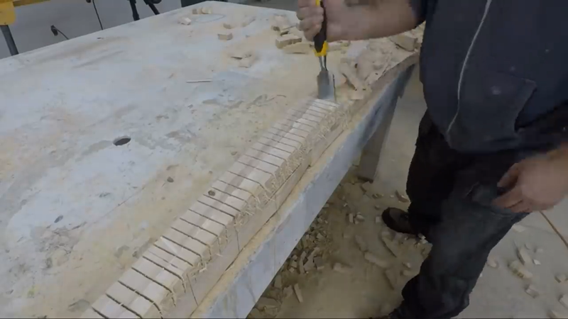
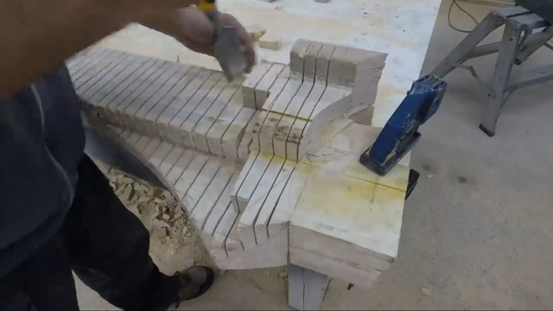
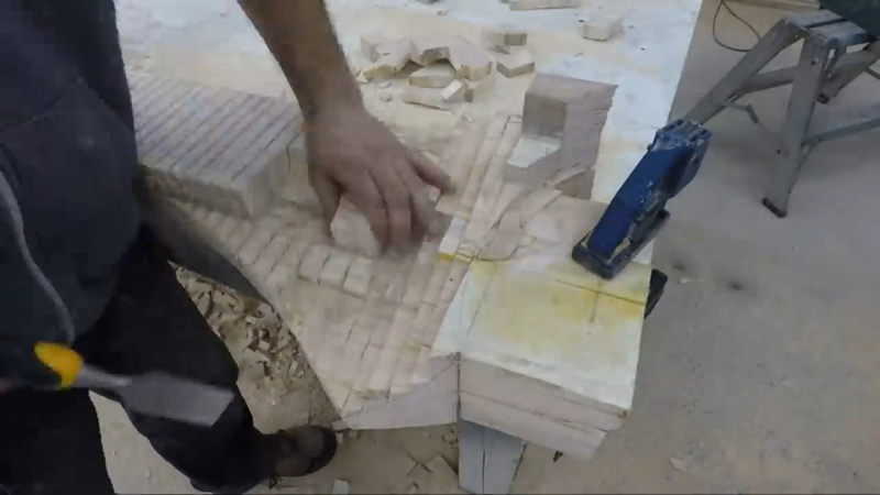
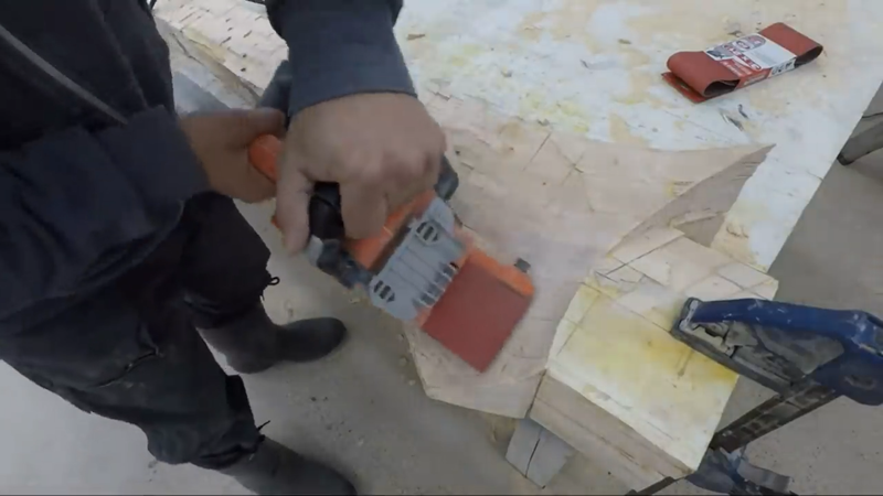
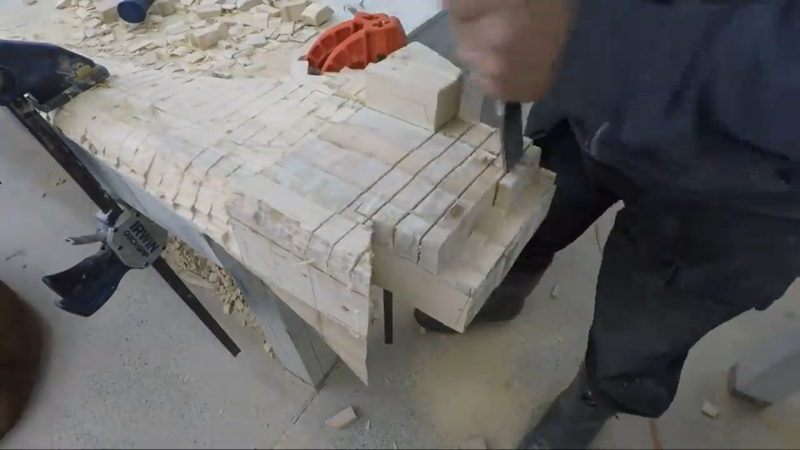
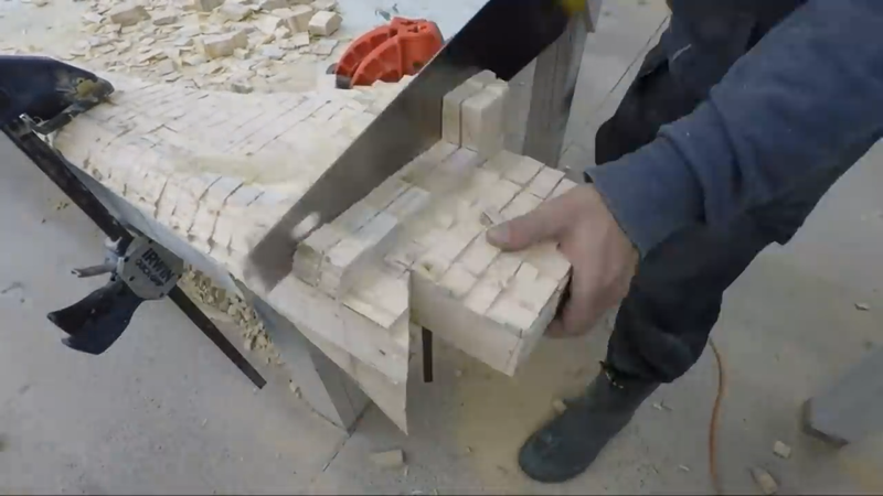
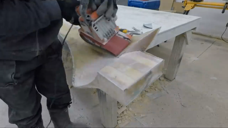
With the stations and trailing edge laid out, I began making a series of cuts along the blade approx. 1" apart, down to the drop marked on the trailing edge and connecting with the top of the leading edge. Then I used a hammer and chisel to break out the pieces and expose the blades new front face, and then sanded it smooth with a belt sander.
I repeated the same process on the back side of the blade, except the drop on the trailing edge had to connect with a line that I drew approx. 2/3 of the distance from the trailing edge to the leading edge, which represents the thickest portion of the airfoil. Then I rounded over the leading edge to finish the airfoil profile.
You'll probably notice that the back of the blade where it connects to the hub is angled a bit (approx. 4°). This will angle the blade tip 4° away from the tower to allow some room for flexing in high winds. Most builders and manufacturers will either keep the rotor plane perfectly vertical or angle the generator with the rotor ~4°, depending on the type of blades they're using (rigid or flexible). But I've found the easiest method is to just angle the blades on the hub and keep everything else level and plumb.
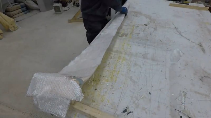
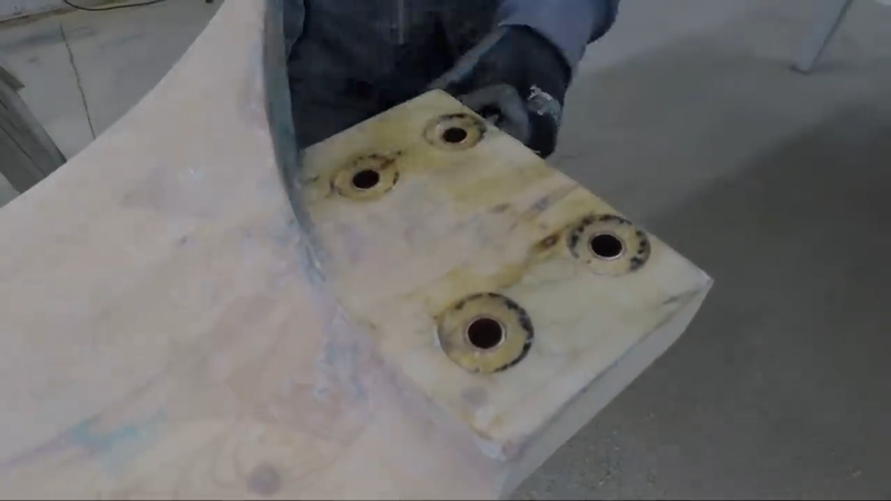
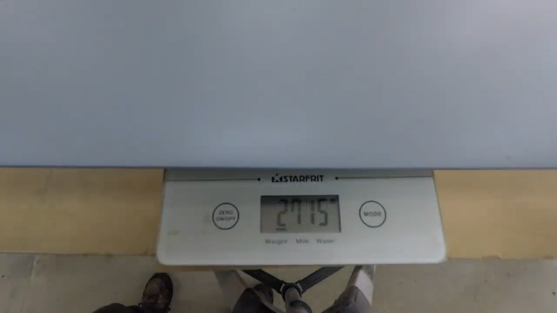
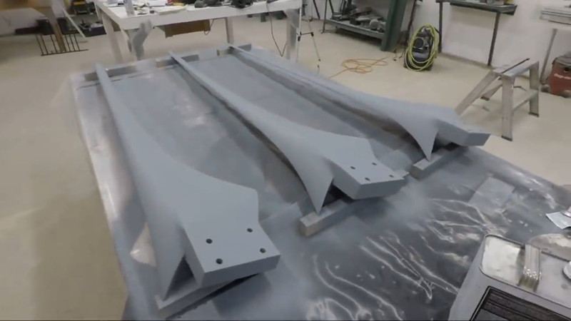
After each blade was sanded, I cut some 10 oz fiberglass cloth and mixed up some polyester resin and put 3 layers of cloth on both sides of each blade. After the resin cured, I trimmed off the waste with an angle grinder, then drilled 4 holes for mounting bolts in each blade. To protect the wood, I epoxied bronze bushings in the holes. Then I sanded the blades smooth, weighed them, and removed more material where necessary so that they were almost exactly the same. When I was satisfied, I finished them with a few coats of paint.
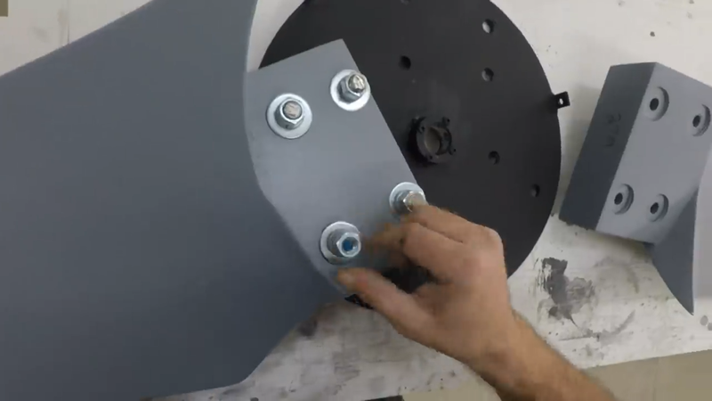
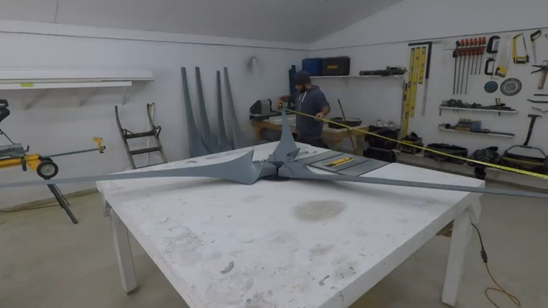
Next, I attached the blades to the blade hub. To help with balancing, I measured the tip to tip distance between each blade. With the bolts just hand tight, I adjusted the blades where necessary to space them apart equally, then tightened the bolts permanently.
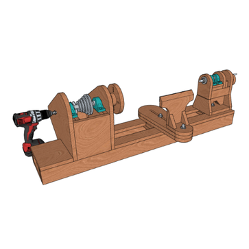
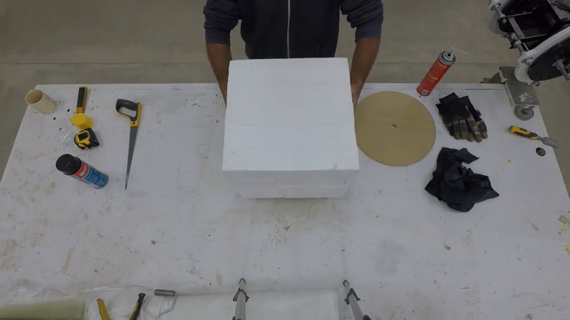
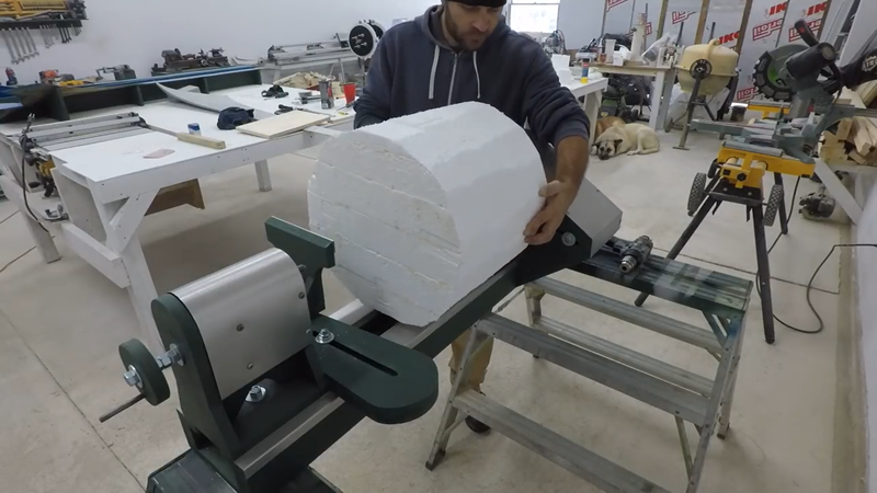
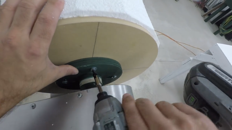
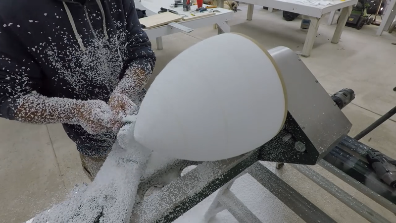
Most DIY turbines don't include one, but I decided to make a fiberglass nose cone to finish off the rotor. First I made a foam plug using my DIY benchtop lathe. A plug is just a model of the part that needs to be cast, which is used to create a negative mold for casting. I covered the plug with filler, sanded it smooth and then painted it.
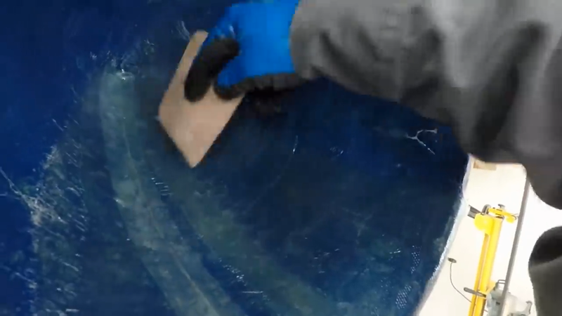
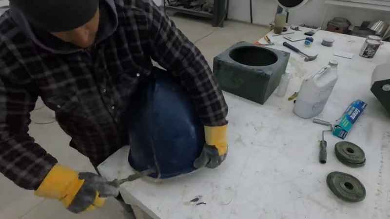
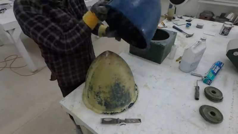
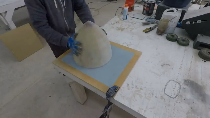
I then covered it with petroleum jelly and put approx. 6 layers of fiberglass cloth and polyester resin over it to make the mold and let it cure. The next day I removed the fiberglass mold from the plug, painted it, and used it to cast the actual nose cone with more fiberglass and polyester resin. In retrospect, I should have used a gel coat on the mold's inside surface or made fiberglass and silicone sock and mother molds because there was a risk of the resin in the cast crosslinking and adhering to the resin in the mold as it cured. Lucky, it didn't this time.
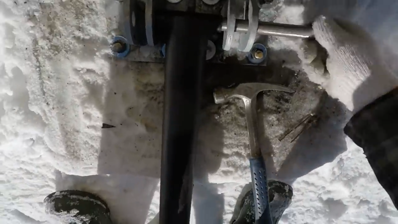
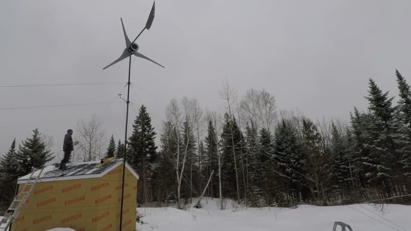
At this point the turbine is ready to install, but I still had to build a tower. It was made with 30 ft of 2.5" schedule 80 pipe, two pieces 15 ft long welded together in the middle. I notched the bottom end to receive a 1" pipe that would form part of the hinge that would be anchored to the reinforced concrete base below the tower and allow it to be raised and lowered with a 1500 lb winch. I made anchor brackets for attaching guy wires and welded them over the joint in the middle of the tower and another set a few inches below where the tip of the blades would be, so there would be two sets of guy wires anchoring the tower in all four directions.
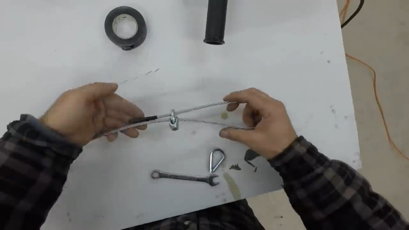
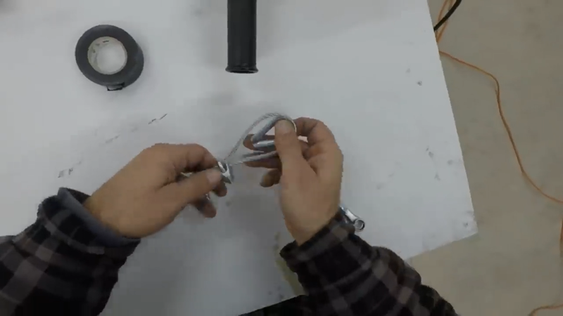
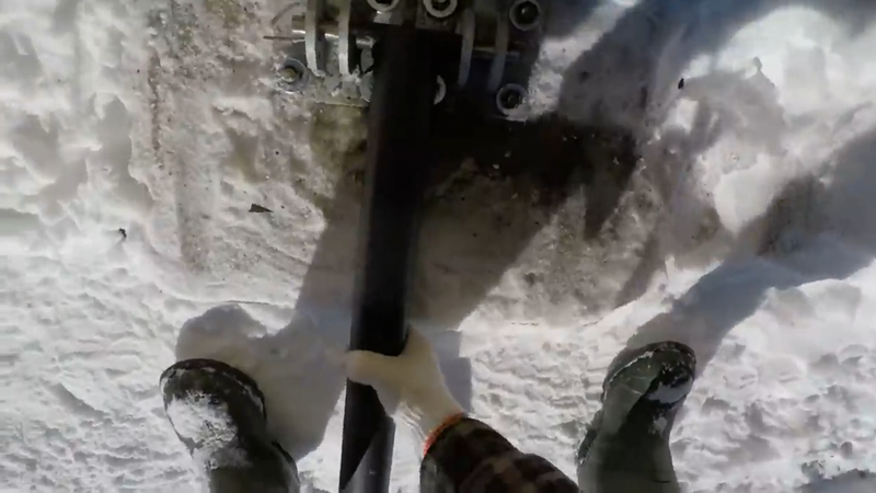
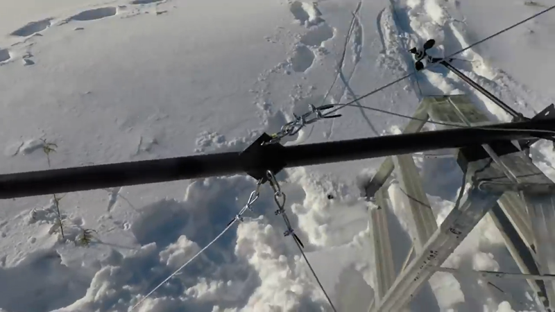
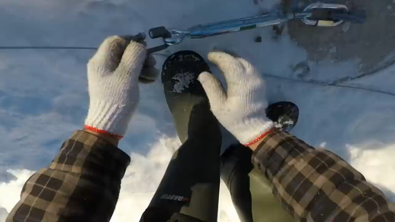
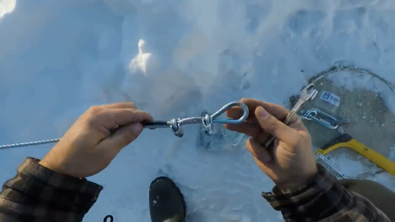
I welded the tower and brackets together in the workshop, then took some measurements outside and calculated the rough length of the guy wires so that I could cut and prep those. I used 5/16" stainless steel aircraft cables for the guy wires, with two cable clamps and a thimble on each end - I only prepped one end in the workshop and finished the other once the turbine was raised and I could cut it to the exact length needed. Something to note for those who've never used wire clamps before, is to make sure the saddle of the clamp is on the live (long, load) side of the wire as shown below - 'never saddle a dead horse', as they say. If the saddle is on the short side of the wire, then it could slip under load.
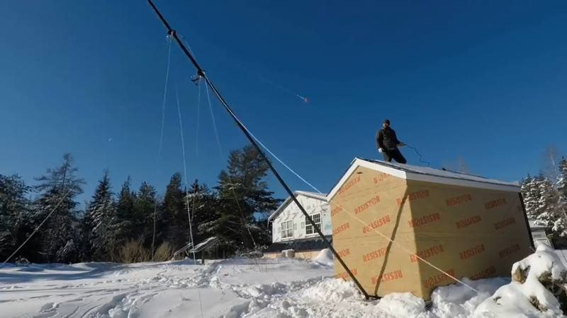
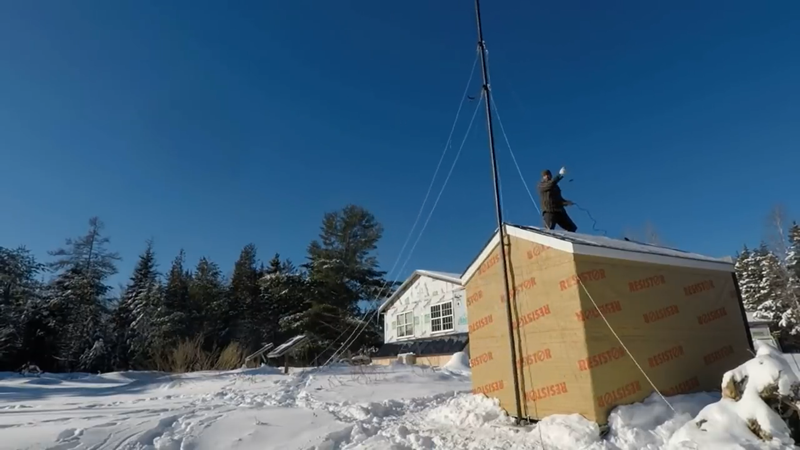
The location I picked for the tower was right at the end of my utility shed. The roof provided a sturdy anchor point for the winch, which was high enough to eliminate the need for a gin pole to raise the tower.
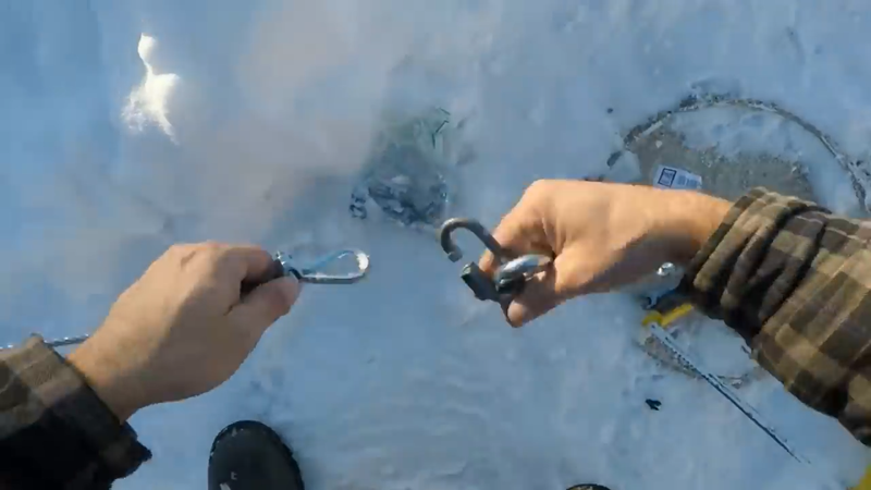
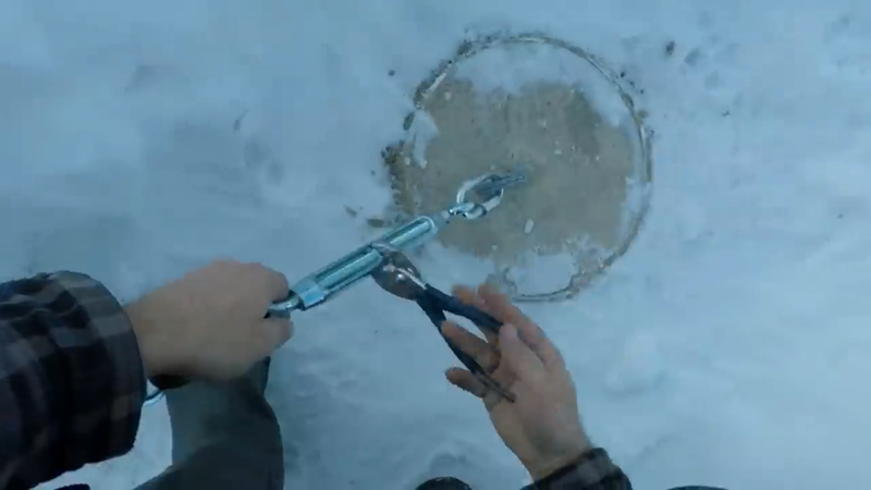
A few months prior to the turbine build, I had dug 2'x3ft deep holes in the ground to pour the concrete guy anchors so they would be fully cured and ready for the installation, so all I had to do was line up the tower with the anchors in the concrete base, insert the hinge pin, lift the tower (without the turbine) into position and then cut the guy wires to length and clamp the ends while the tower is still attached to the winch, and connect them to their ground anchors with turnbuckles.
Once I had the guy wires set, I loosened them all and disconnected the one wire that ran parallel to the winch cable so that I could lower the tower again. Theoretically the other three wires can stay connected as long as they're close to the same elevation and length.
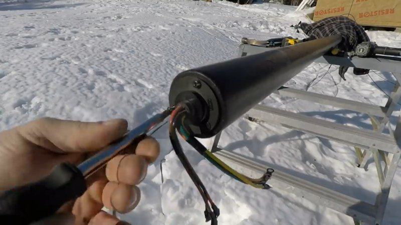
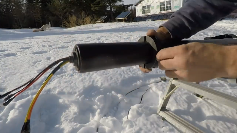
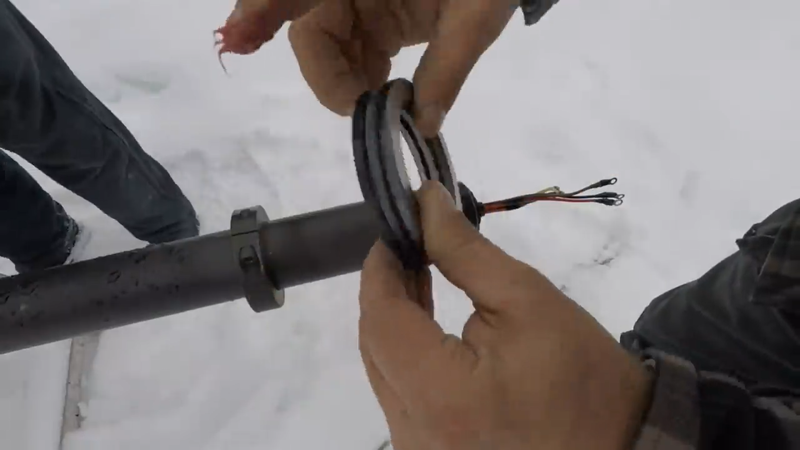
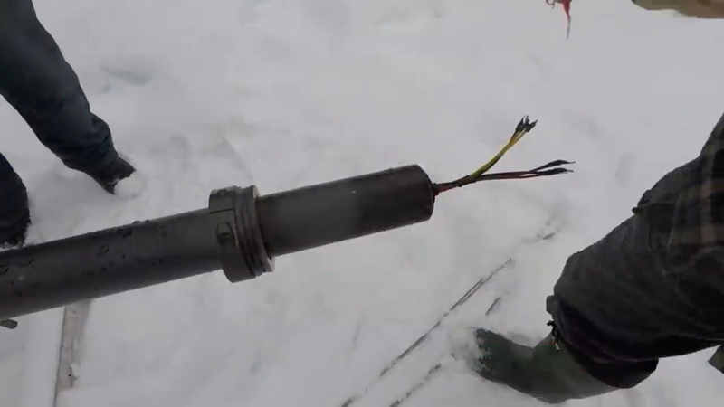
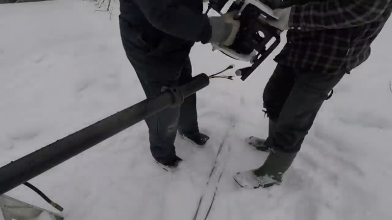
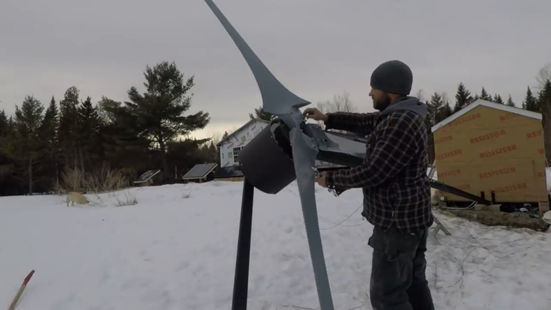
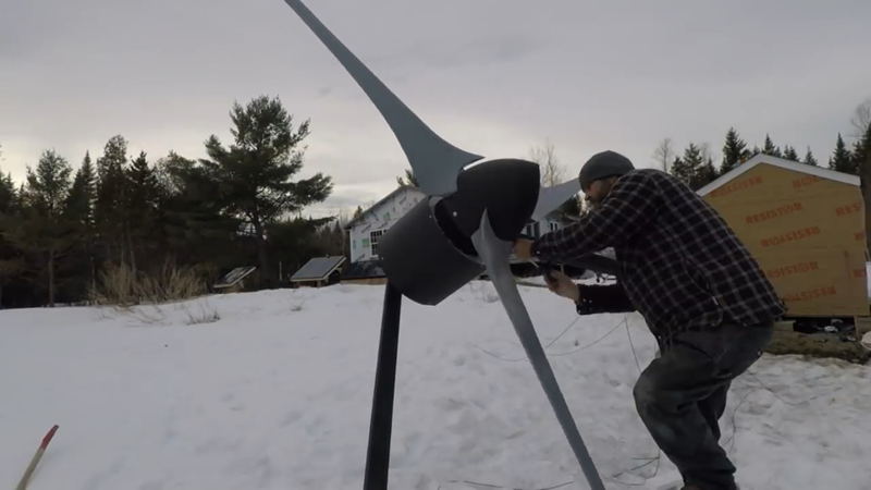
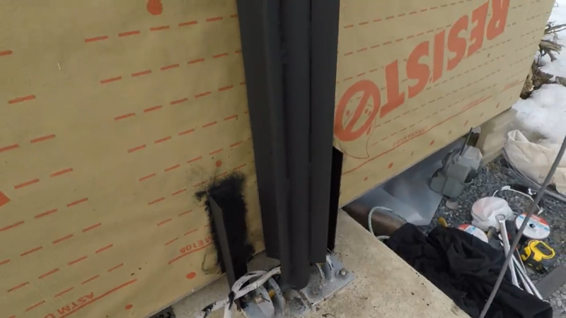
I then fished the transmission cables from the charge controller in the house, through the tower and out of the top of it. To help keep the cables from twisting up in the tower over time, I installed a slip ring. This device transmits power from the generator to the transmission cables using brushes and cylindrical contacts that the brushes rotate around, like the brushes and commutator in some power tool motors. It has 6 input wires and 6 output wires (one wire per phase), each capable of handling 30 amps continuously. After the slip ring was installed, I installed a 2.5" split locking collar and axial bearing on the tower for the turbine to rest on, then my dad gave me a lift to install the turbine onto the tower. The generators were then wired to the split ring and the tail was installed.
Finally it was time to install the blade set. I bolted the hub to the rotor shaft and then gave the blades a few spins by hand to determine if there was a heavy side or not, which would be indicated by that side always coming to a rest while pointing to the ground. There was a heavy side, so I added a couple more nuts to the mounting bolts on the opposite side and that balanced things out. I had also installed an anemometer a few inches below the blades to measure real time wind speed with the power output from the controller.
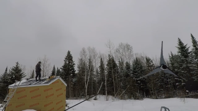
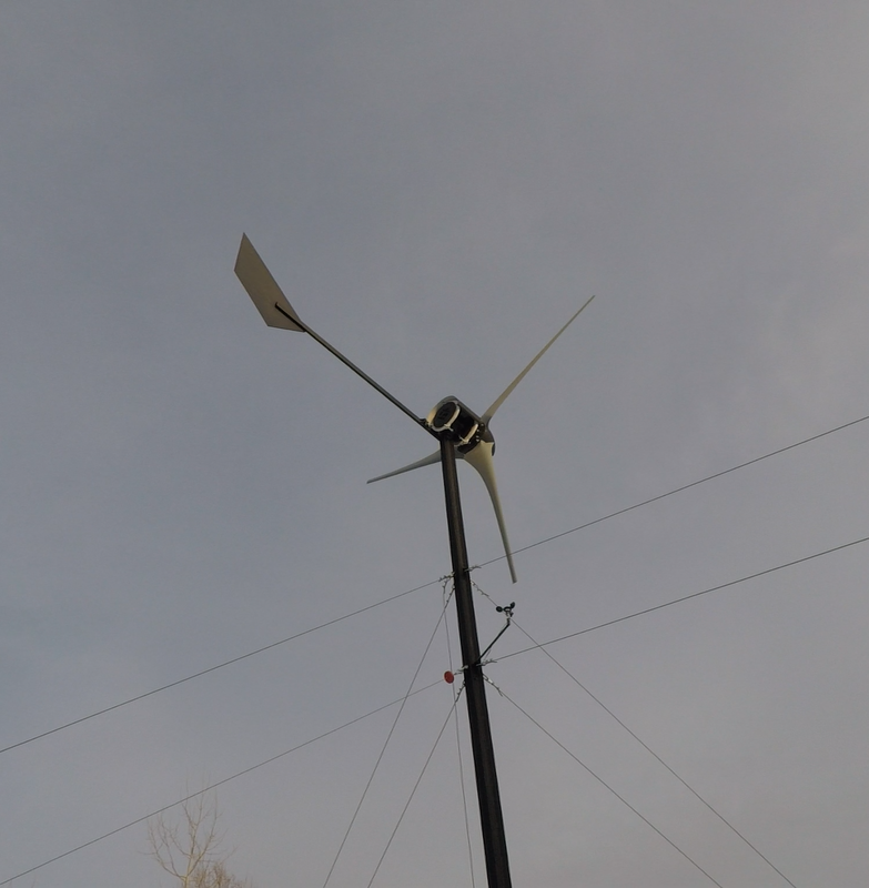
After turning on the electrical brake in the house to keep the blades from spinning until I was ready, the turbine was raised into the air and the guy wires were anchored in place. Then I turned the Midnite Classic charge controller on in the house and turned the turbine brake off to begin charging my battery bank. The turbine began spinning almost immediately after turning off the break. I don't know what the start up speed is because it's too low for the anemometer to measure (only whole numbers). The cut-in speed was very low, around 5 mph and it began charging. The tower is about 20 ft too low for this area and it gets a lot of turbulence off the trees as a result, but I've seen the occasional gust of 28-30 mph generate between 2500-3000 watts. On avg with the 10 mph mean annual wind speed, here, it produces around 500 watts per hour, or ~500 kWh per month. That's a majority of the energy that a bachelor like myself uses, and a good chunk of the energy demand of a typical family. You can watch the power performance video here showing slightly more than 2600 watts being produced in a 24 mph wind. |
AuthorJames Biggar Archives
March 2023
Categories |












































 RSS Feed