|
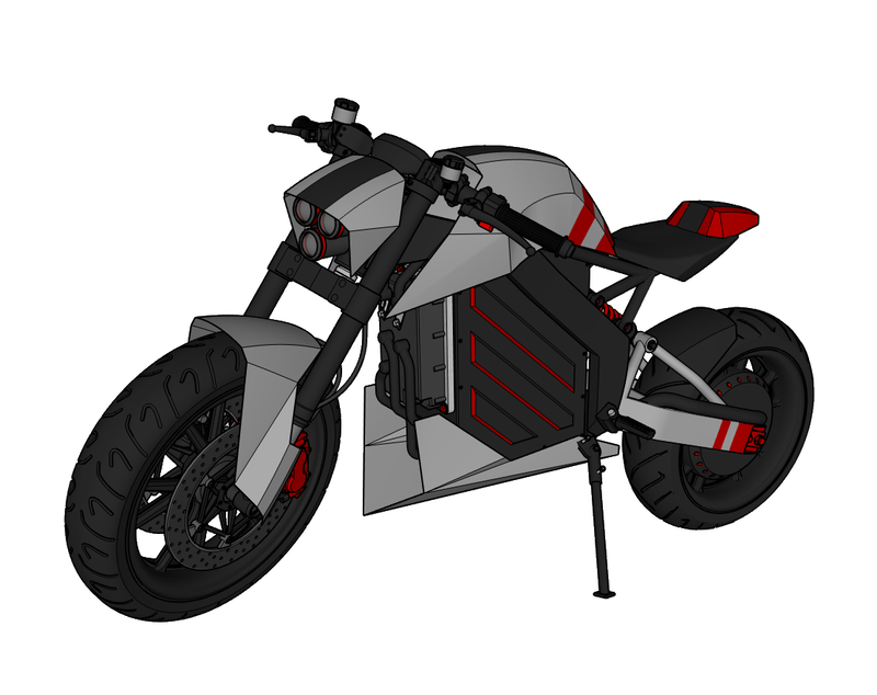
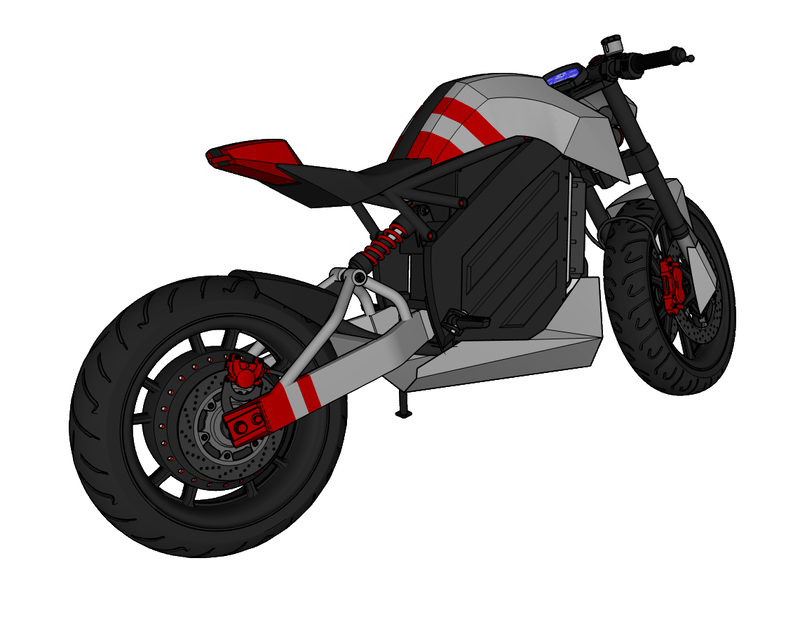
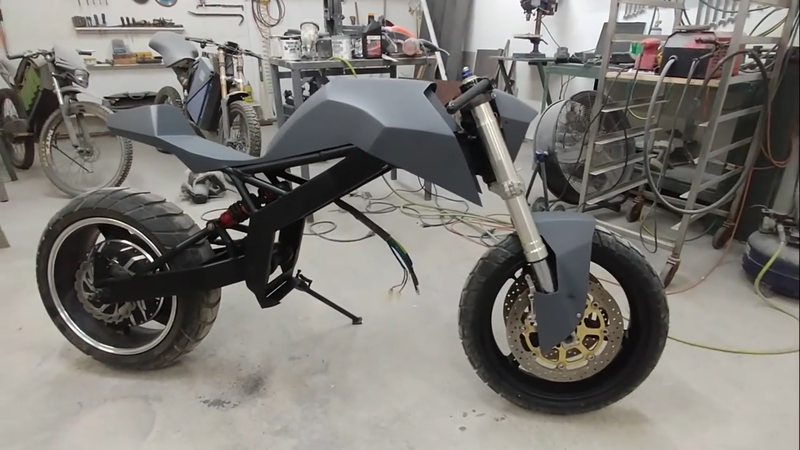
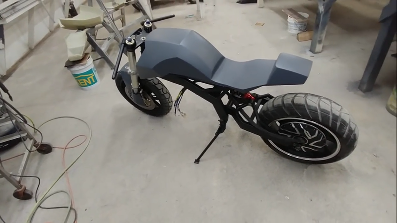
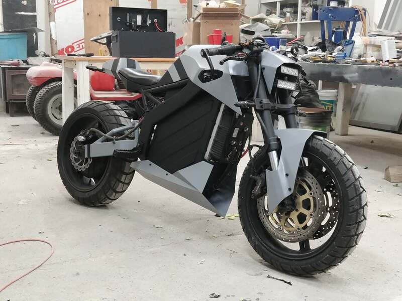
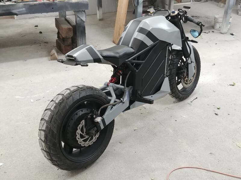
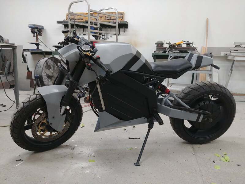
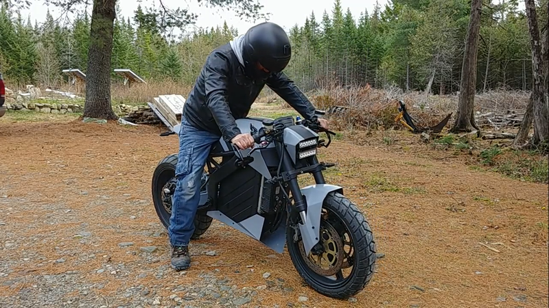
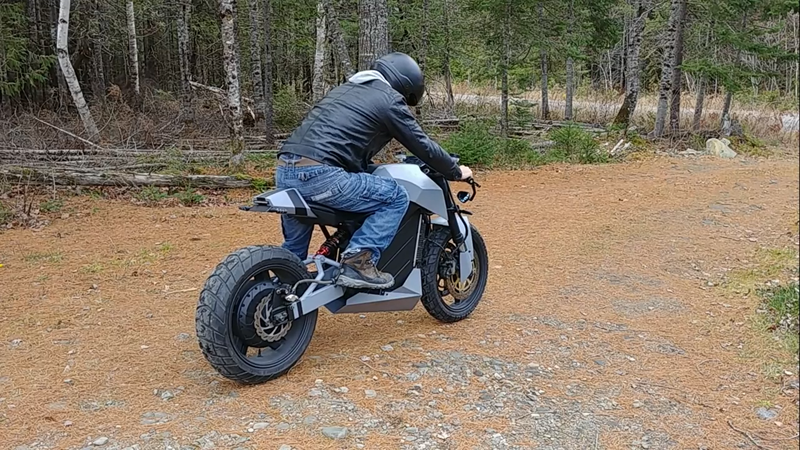
In this video I build an original custom electric motorcycle from scratch for less than HALF the price of an equally sized ZERO S (~$5000 Canadian). This aggressive looking streetfighter uses the same 24 kW (32 hp) drivetrain as the previous Cyber Trike project. Though equivalent to most 300cc street bikes in overall power, this little monster boasts a massive 250 ft-lb of max starting torque and only weighs 300 lbs. This produces a neck-snapping acceleration rate of over 8 m/s^2.
However, as force (hp or watts) = speed * torque, we can't increase the torque from a given amount of horsepower without taking from the top speed. Where the R1 lacks in torque, it makes up for with a top speed of 300 km/h (186 mph)...that's where all that extra hp goes to, and is what makes it better suited for a race track vs the street. But electric motors can generate more torque and reasonable top speed with less hp because they're much more efficient. The top speed for this electric streetfighter is 120 km/h @ 72V, and 150 km/h @ 120V, which is more than fast enough to get you a speeding ticket on any North American highway. Together with the white-knuckle torque specs, this makes for an ideal combination for a really fun street machine.
Specs:
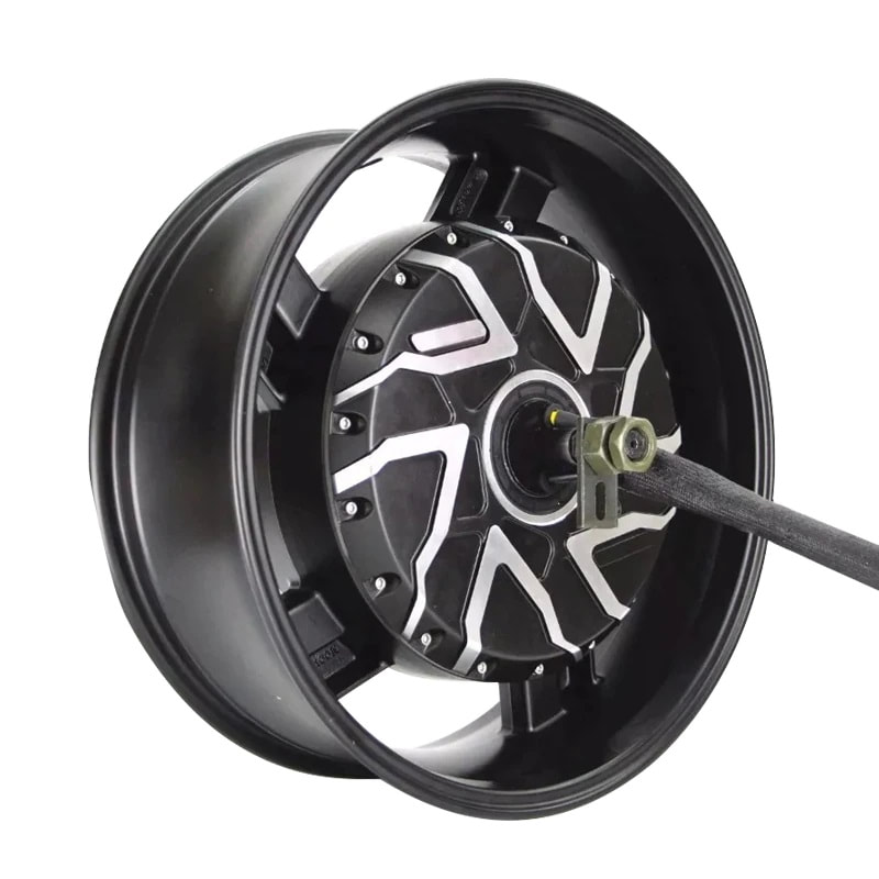
Power: 12 kw/ 24 kWp, 32 hp gross Motor: QS273 70H brushless hub motor Battery: 74V/4.3 kWh LiFePo4 Range: up to 100 km's Top speed: ~115 kph (71 mph) @ 72V, 150 kph (93 mph) @ 120V Max torque: 350 Nm (258 ft-lb) Controller: Kelly KLS72601 Wheelbase: 55" (140 cm) Rake angle: 26° Trail: 4.9" (124.5 mm) Turning radius: 72" (183 cm) Weight: 300 lb (136 kg) Front suspension travel: 5" (130 mm) Rear suspension travel: 8" (203 mm) Front tire: 120/70-17 Shinko 705 Rear tire: 180/55-17 Metzler Karoo Street
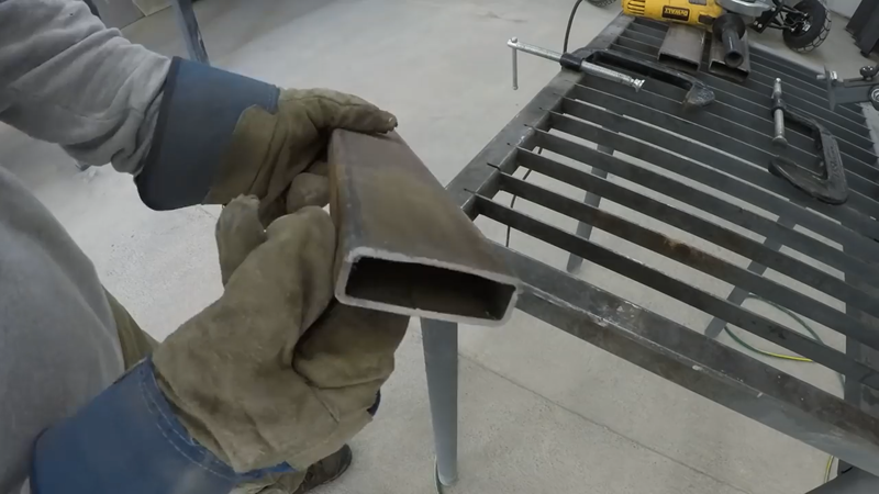
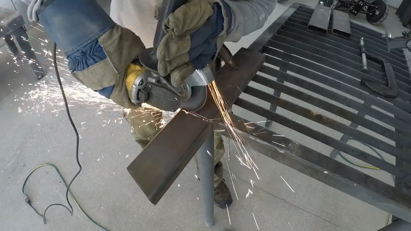
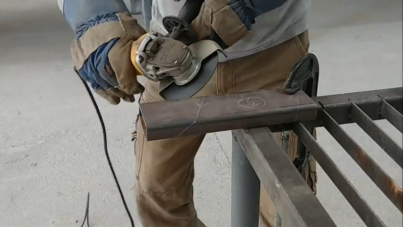
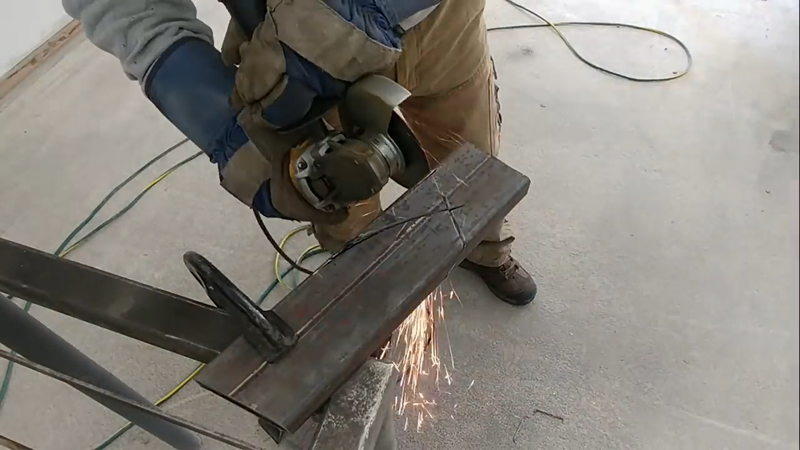
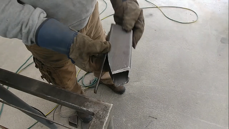
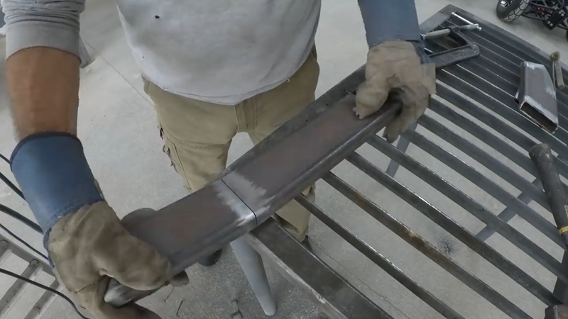
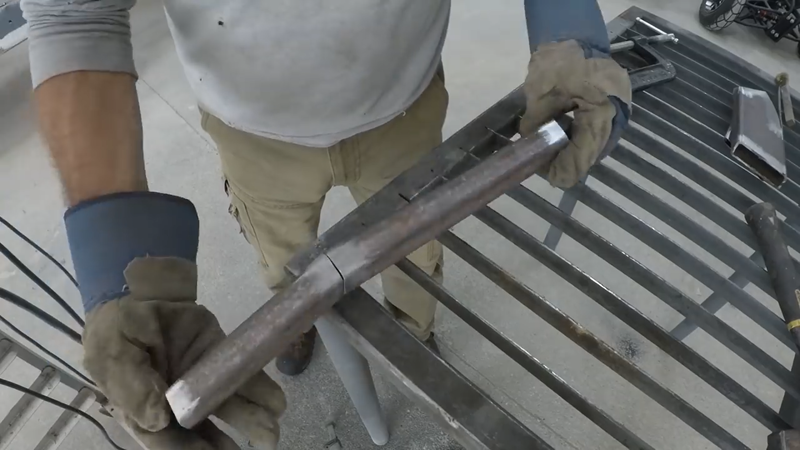
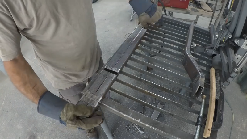
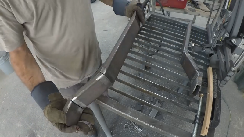
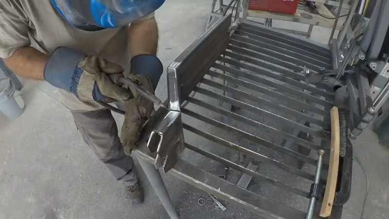
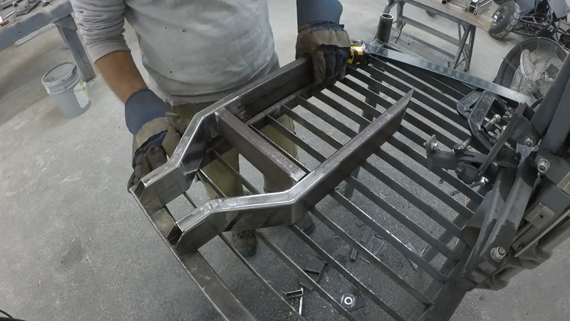
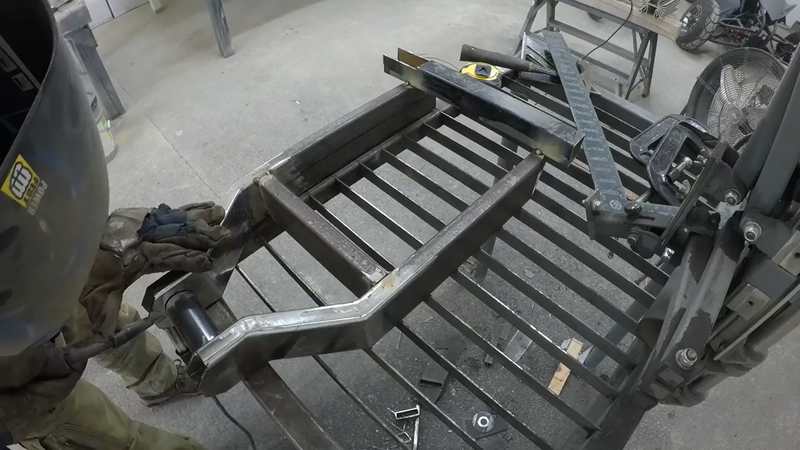
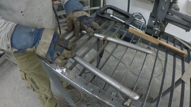
I started the build by fabricating the main frame out of 1x3x0.12" rectangular steel tubing. I didn't have a tube bender at the time, so I cut and welded mitered joints instead of bending. Where possible, I cut only three sides of the tubing and scored the fourth so that it could be bent by hand. This saves a bit of time cutting and also holds the pieces accurately in place for welding without needing complicated fixtures and clamps.
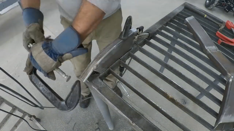
Once the pieces for each side of the main frame were cut and shaped, they were tack welded together and then the sides of the frame were temporarily connected with 1x1" crossmembers to hold them in the right position for fitting the head tube and sub frame later.
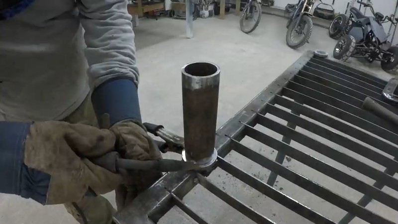
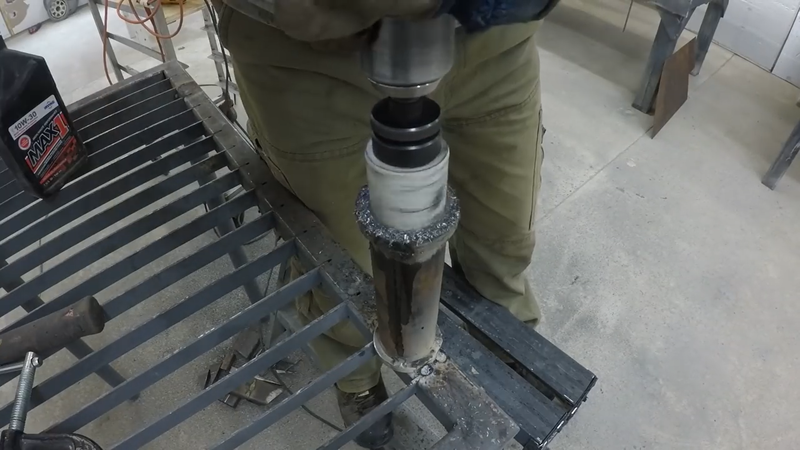
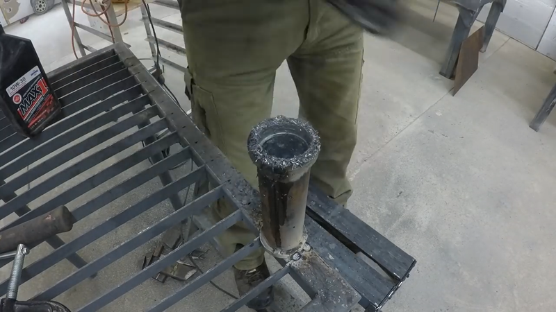
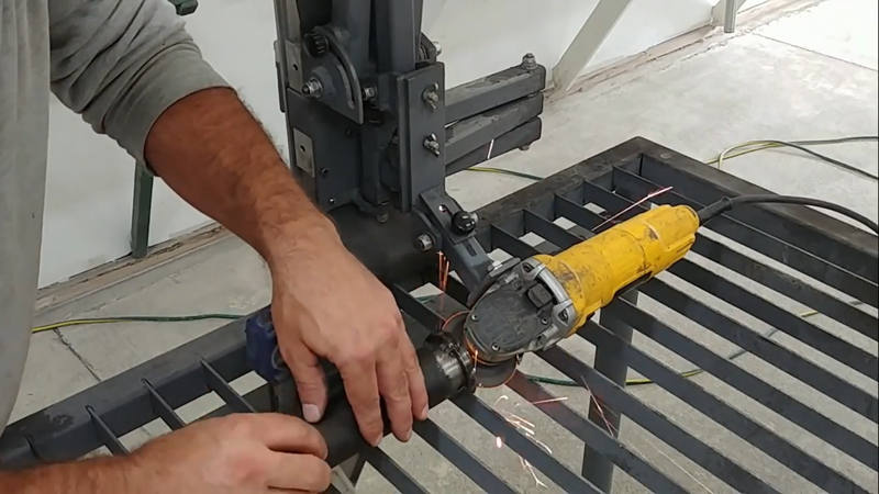
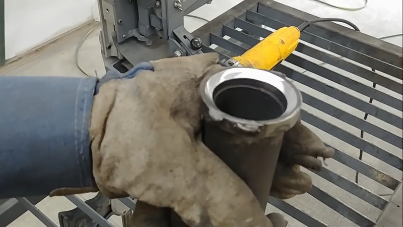
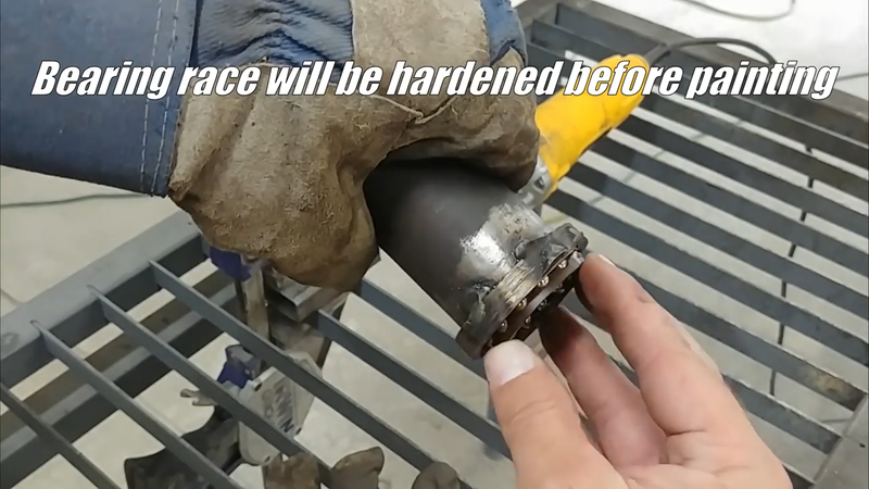
I then made the head tube from 2-1/2" DOM steel tubing. I opted to experiment with making my own bearing race cups from 3/8" high strength steel plate using a small grinding wheel on an angle grinder that's securely fixed to my modular tool guide. The DIY cups worked out pretty good after they were heat treated. However, I recommend buying replaceable race cups instead. The ones that I made will need to be removed and replaced eventually, which would be easier to do if they weren't welded in placed.
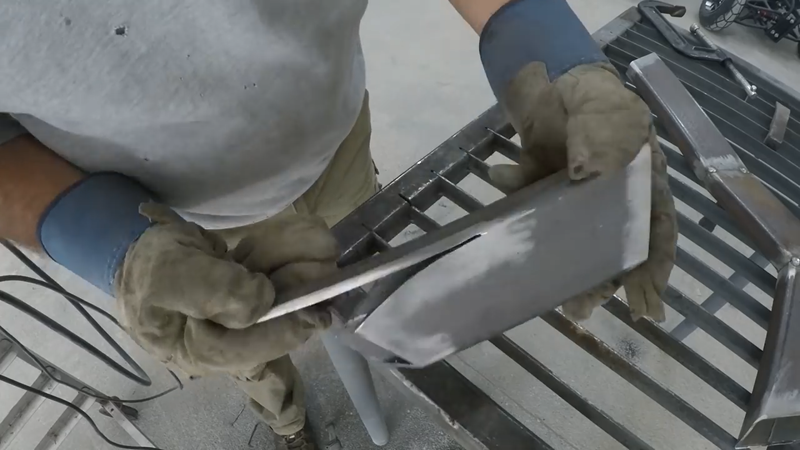
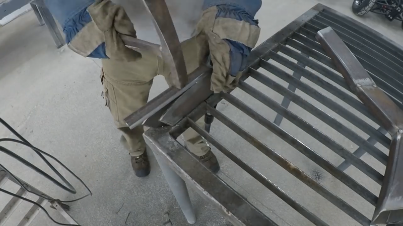
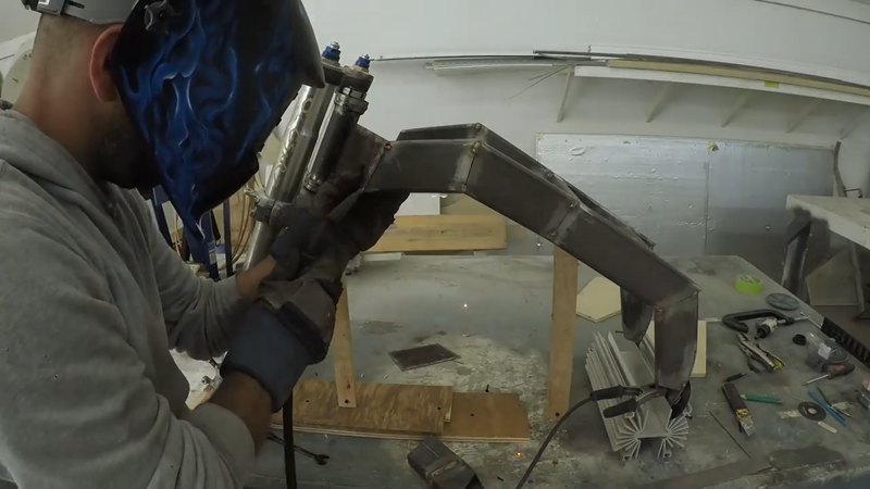
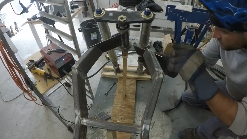
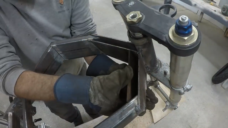
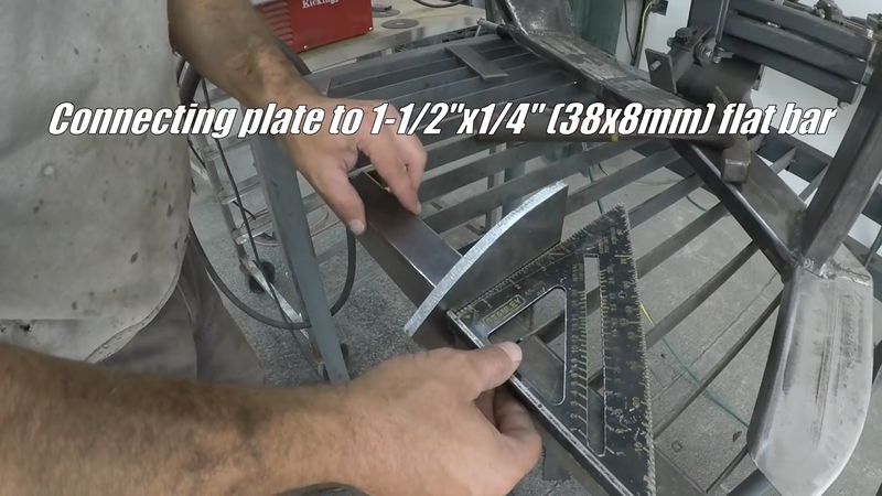
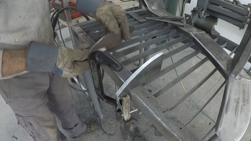
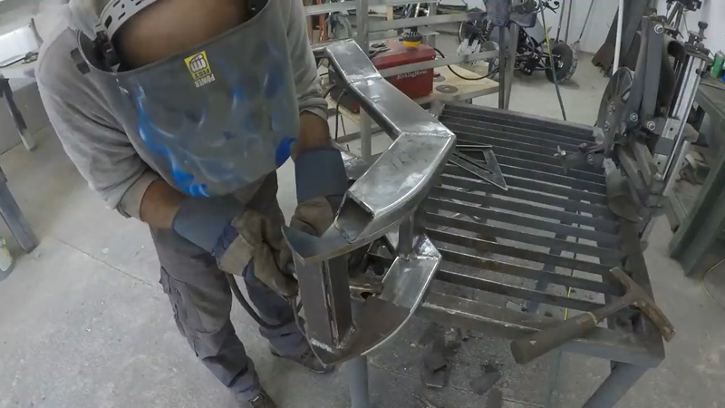
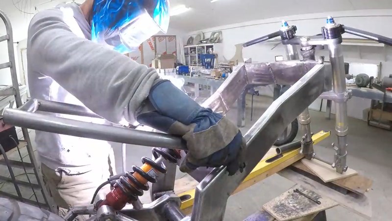
The head tube was placed onto the GSXR front forks that I chose for this build, and then I set up the main frame and forks together on a level surface to prep for connecting the head tube to the frame. The forks were set to a 26° angle from vertical to match a typical sport bike. I then connected the head tube to the frame using two pieces of trapezoidal shaped box tubing made with 1/8" mild steel plate.
Once the head tube was attached, I welded all of the joints in the main frame sequentially to avoid distorting it as the metal expanded and contracted with the heat from the welding.
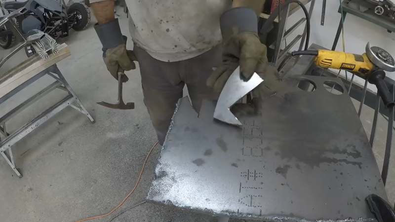
Next, I cut the lower battery mounts from 3/8" mild steel plate and welded them to the frame.
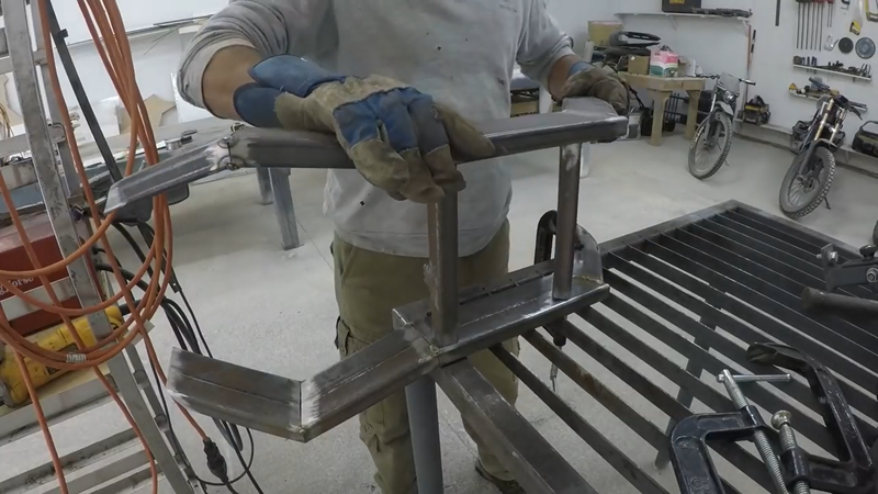
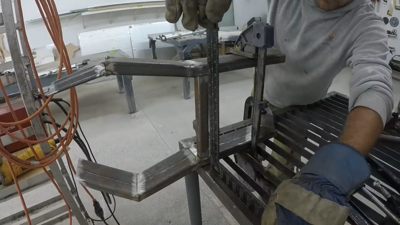
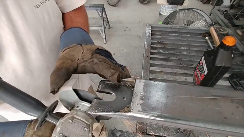
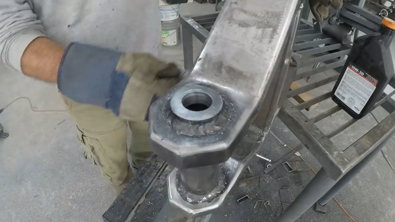
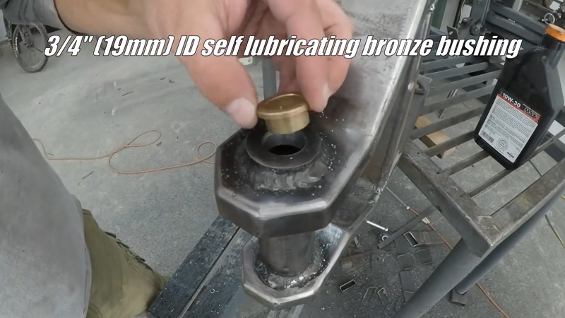
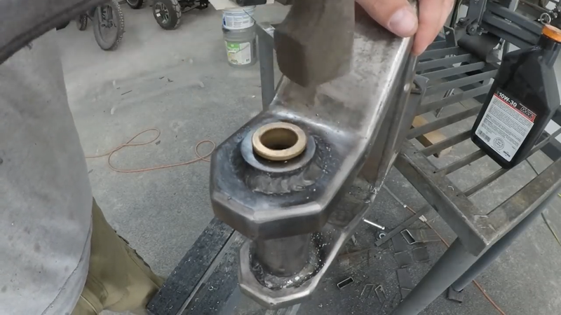
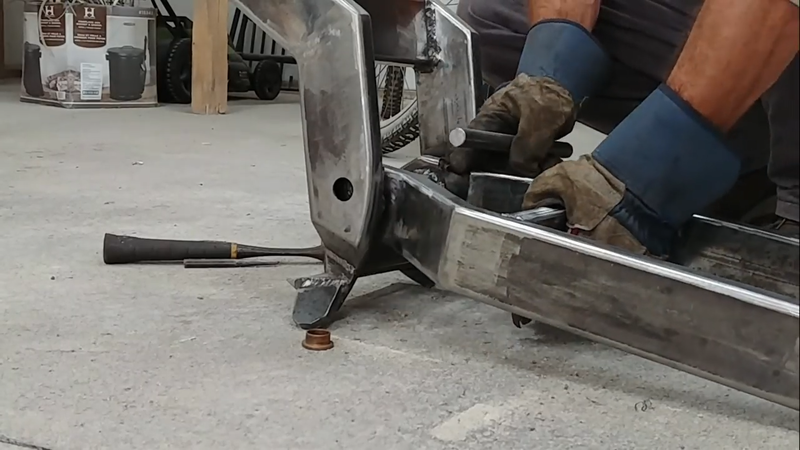
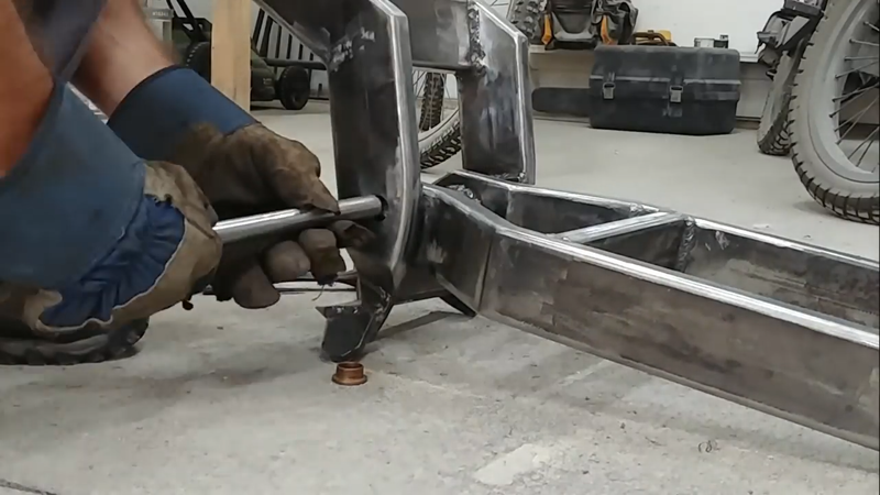
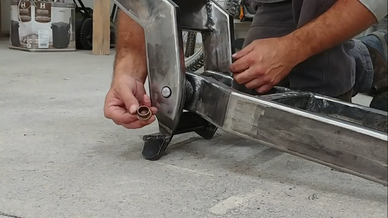
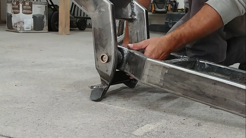
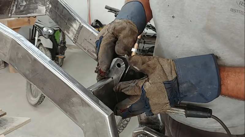
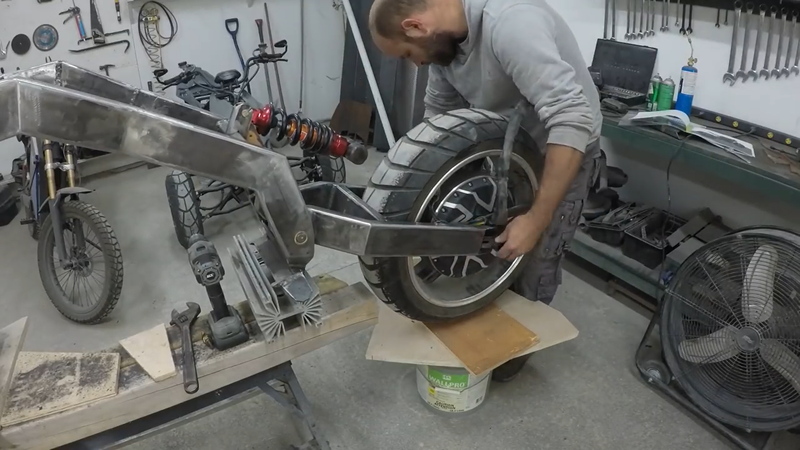
Then I made the swingarm from 1x3x0.12" steel tubing using the same mitering method that I used for the main frame. A piece of 1x3" tubing served as a crossmember to attach the two main tubes of the swingarm together at the middle, and a piece of 1-1/2" DOM tubing was welded between them at the front. The back ends of the swingarm tubing were then drilled and notched for the hub motor axle and torque arm, and the front end of the swingarm was drilled to receive 3/4" ID self lubricating bronze bushings.
I'm asked a lot why I used bushings instead of bearings, and my answer is always 'what's the difference'? A bushing is a bearing, a plain bearing, technically. Different types of bearings serve different purposes. Bushings are very strong bearings that are designed specifically for low speed, high load applications, such as on a swingarm pivot bar, or suspension linkages, and even in heavy equipment booms and boom attachments that move or rotate slowly but support a heavy load. The more popular but far more expensive ball or roller type bearings are specifically designed for high speed applications, like an axle bearing for a wheel travelling at ~1000 rpm. They generally have a lower load rating compared to bushings, however, because they're exposed to higher speeds. Of course, nothing says that you can't use a ball or roller bearing for the swingarm bar just like all the major bike manufacturers, but there's really 0 benefit to it. Both a bushing and a bearing will provide more than sufficient stability and will wear at similar rates in this application. The difference is mainly just cost, aside from the fact that the bushing will operate quieter because it's impregnated with oil to be self lubricating, which avoids the need for multiple rollers packed with grease. When you're building a custom machine on a budget, cost benefit decisions matter. When you're building a custom electric bike that has next to no engine noise, you're going to want to limit the amount of noise it makes when the suspension is travelling over bumps.
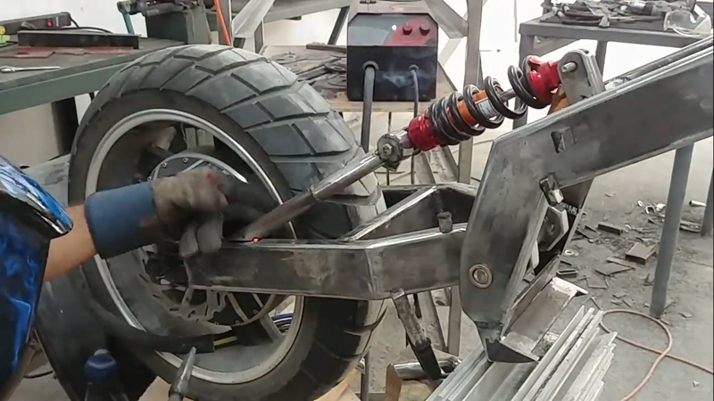
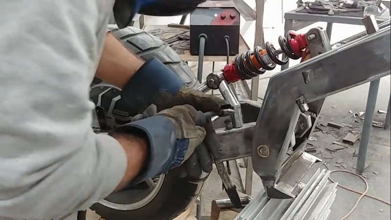
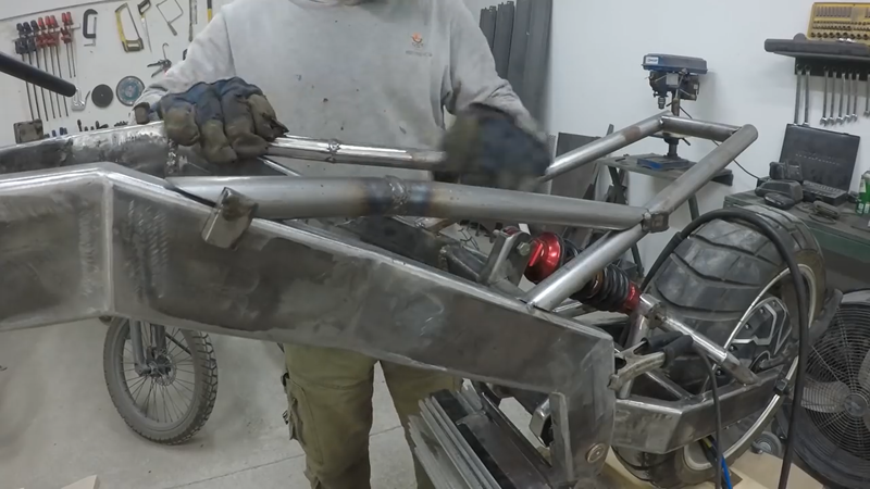
I connected the swingarm to the frame with a 3/4" stainless steel shaft, and then made the rear suspension mounting bracket for the frame and installed the rear shock absorber. I placed the shock to establish the position of its other mounting bracket on the swingarm, then cut a piece of 1-1/2" DOM tubing, capped and drilled the ends and bolted it to the 'free' end of the shock. I then cut and mitered some 1" DOM tubing and welded it as reinforcement between the swingarm and the shock mount.
After the swingarm was finished, I made the subframe for the seat using 1" DOM tubing.
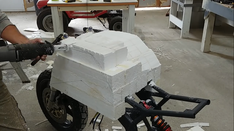
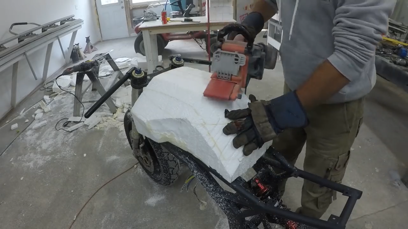
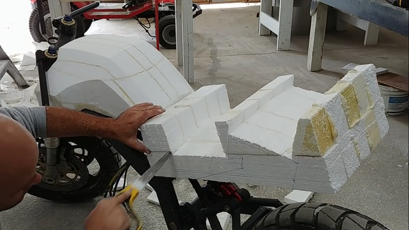
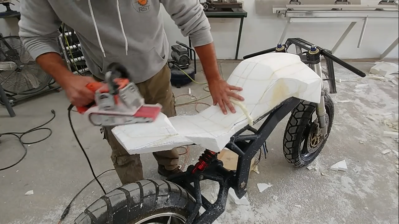
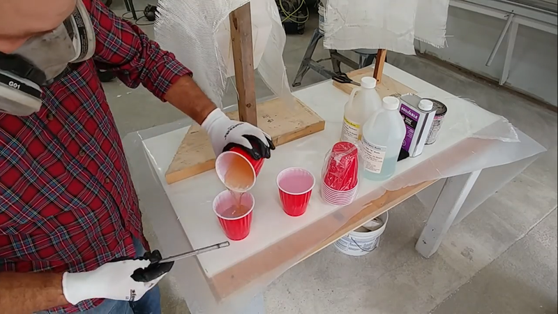
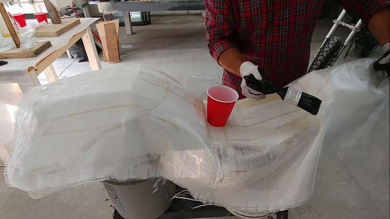
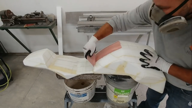
The next task was to make the fiberglass fairing. But first, I need to make a plug to make the mold to make the fairing. The fairing can be made with a 3D printer instead, but I don't own one (yet). The plug is basically just a polystyrene model of the fairing. I carved it using saws and a knife, and smoothed the surface slightly with sandpaper. Then I mixed up some laminating epoxy and brushed it onto the plug quickly before covering it with 2 layers of 10oz fiberglass cloth. It's important to point out here that epoxy was used instead of (polyurethane) resin because resin will melt polystyrene foam, which would have ruined the plug. Laminating epoxy will not damage the foam.
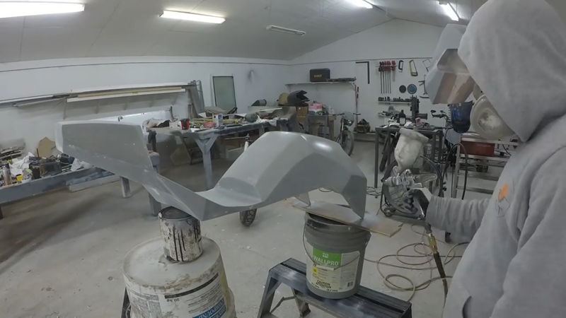
Once the epoxy had cured a day later, I sanded and smoothed the surface with epoxy filler, then painted and finished it with a lacquer finish.
I made the molds in two parts using two different materials, called 'sock and mother' molds. The 'sock' mold will be the finish mold used to cast the parts, and will be made from a flexible RTV mold silicone. The flexibility of the silicone will make demolding casts easier without damaging anything. But because the silicone sock molds are flexible, they need a strong support. This is the purpose of the 'mother' molds, which will be cast in resin and fiberglass.
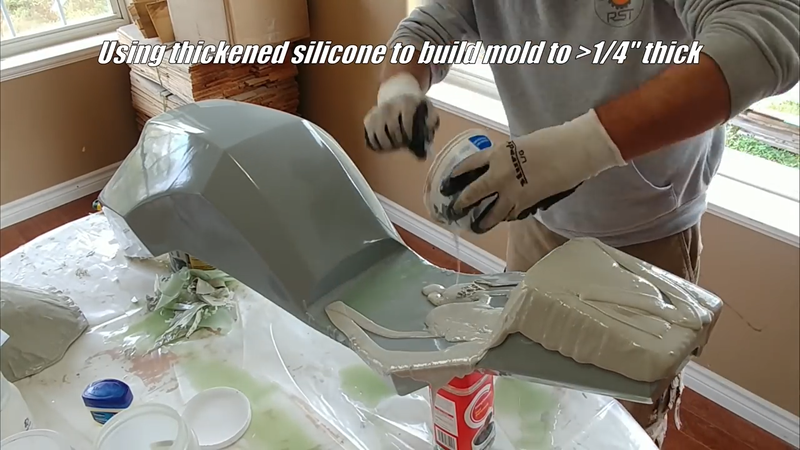
The first step was to apply a release agent to the surface of the plug. I usually just use petroleum jelly but there are commercial release agents available as well. Then I mixed up some regular RTV mold silicon and applied 2 thin coats to the plug and let it cure overnight. The next day I added a thickening agent to a new batch of silicone and applied a thick layer over the existing silicone poured onto the mold the day before. I built up the thickened layer to somewhere between 1/4-1/2" thick on the plug. Making it thicker won't hurt anything other than cost, but I recommend not making them less than 1/4" thick because large sock molds tend to get too floppy and weak if they're made too thin.
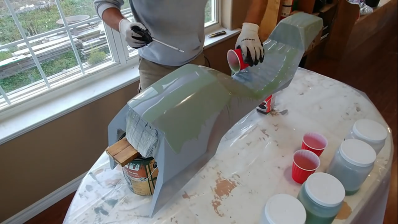
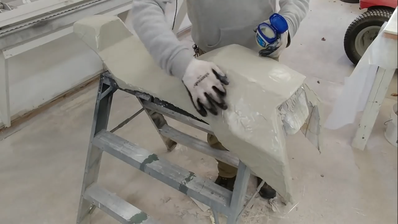
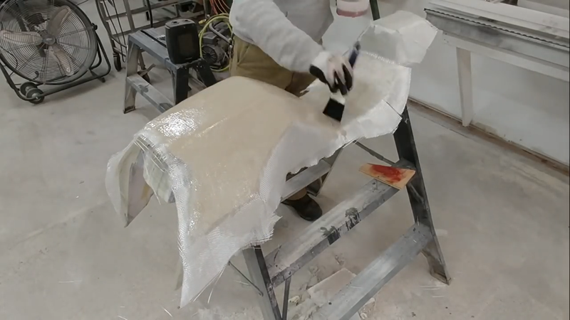
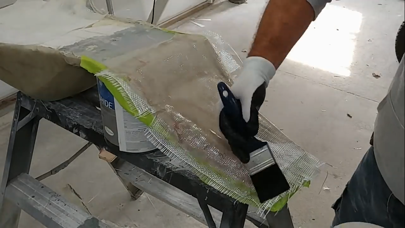
After the silicone sock molds were cured, I left them on the plugs without disturbing them, and started the mother molds by applying a layer of petroleum jelly onto the silicone, and then 4 layers of fiberglass cloth and polyester resin. I used polyester resin this time because it won't damage the silicone and it will cure much quicker than epoxy. After the fiberglass cured, I removed the molds from the plugs. The sides of the molds were quite steep, so to make casting the actual fairing parts easier and eliminate the risk of the cast collapsing on itself, I cut the molds into smaller pieces.
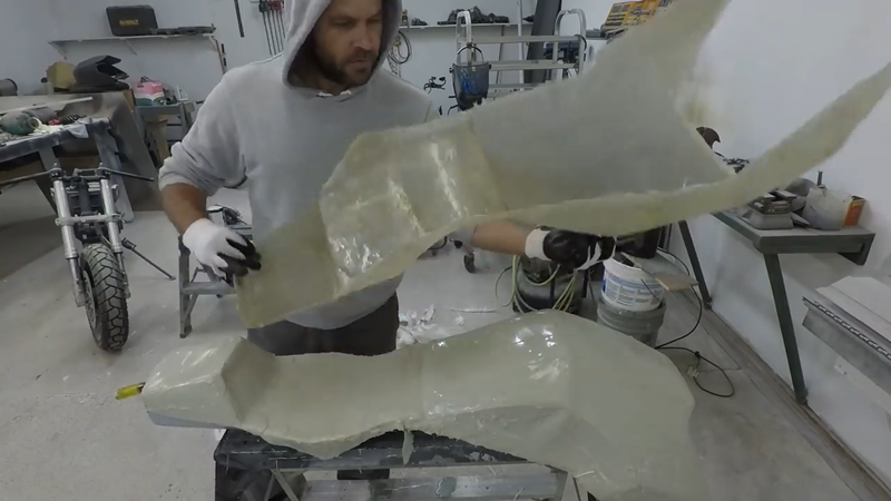
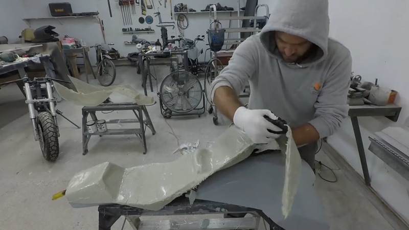
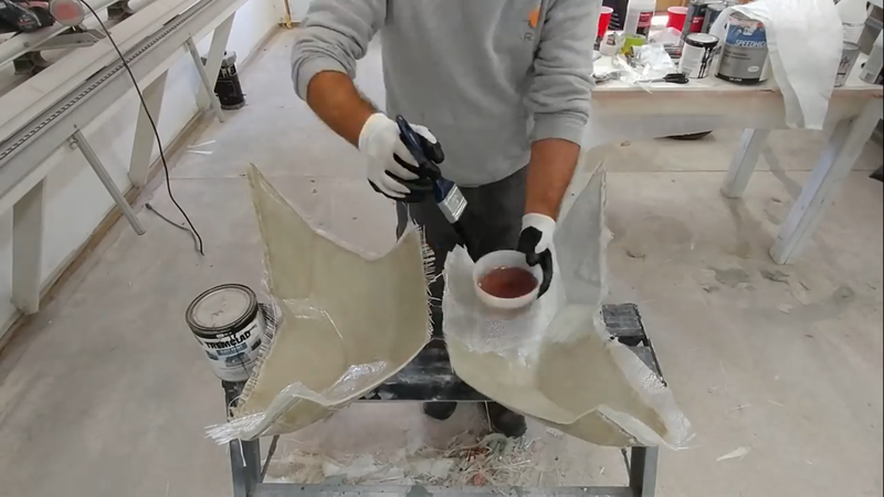
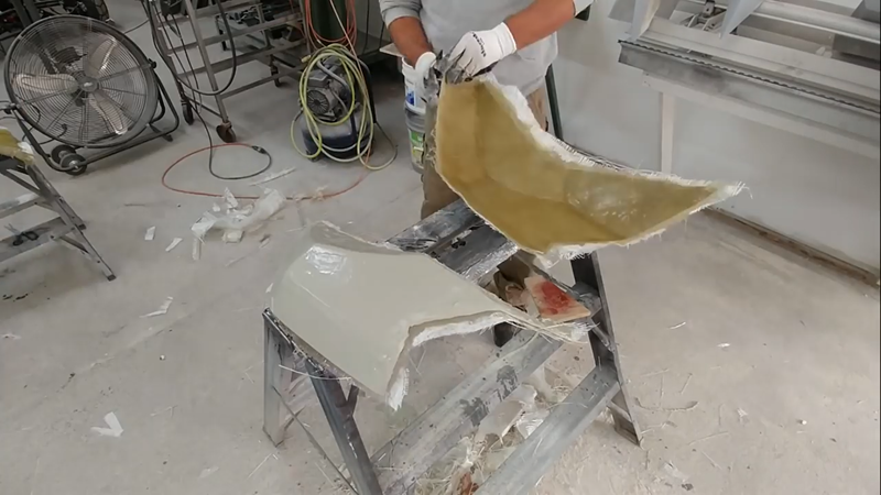
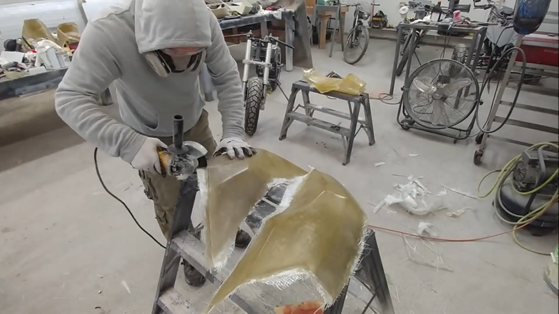
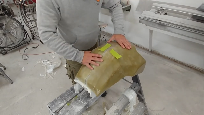
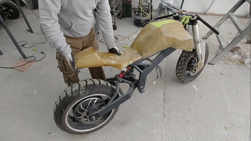
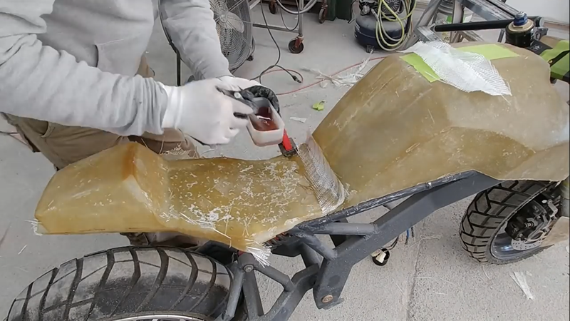
Then I applied more release agent to the sock molds inside surface and cast the fiberglass fairings. After they had cured, I demolded them, trimmed the edges with an angle grinder, and attached the fairing parts together using fiberglass strips and resin. Then I repaired any air bubbles and blemishes with polyester filler, sanded, primed and then painted them.
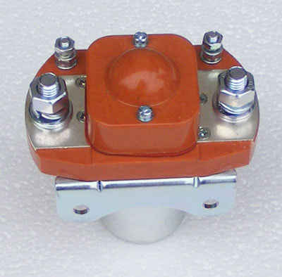
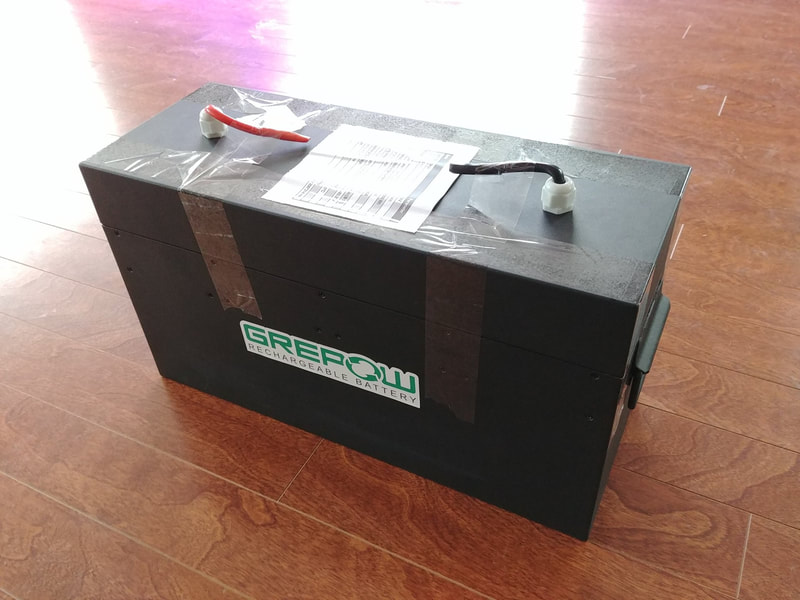
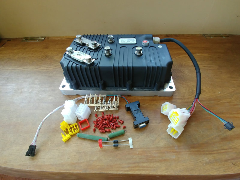
After the messy work was done, I could finally start wiring the drive system according to the schematic shown below. I used the 74V/60 ah LiPo battery that Grepow had custom built for the Cyber trike project, with a KLS72601-8080H controller from kellycontrol.com, and a QS 273-70H hub motor. I incorporated a 400A contactor to turn power on and off to the controller with a key switch, and used a 72-12VDC step down voltage converter to operate the 12V light and horn circuits.
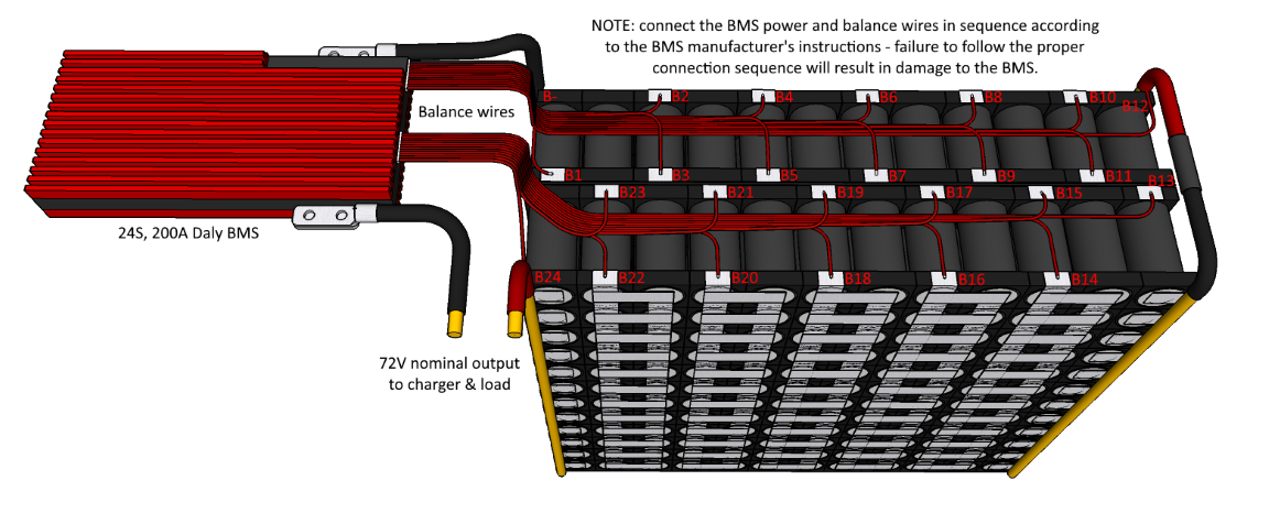
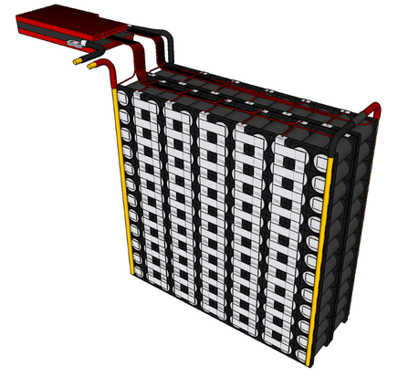
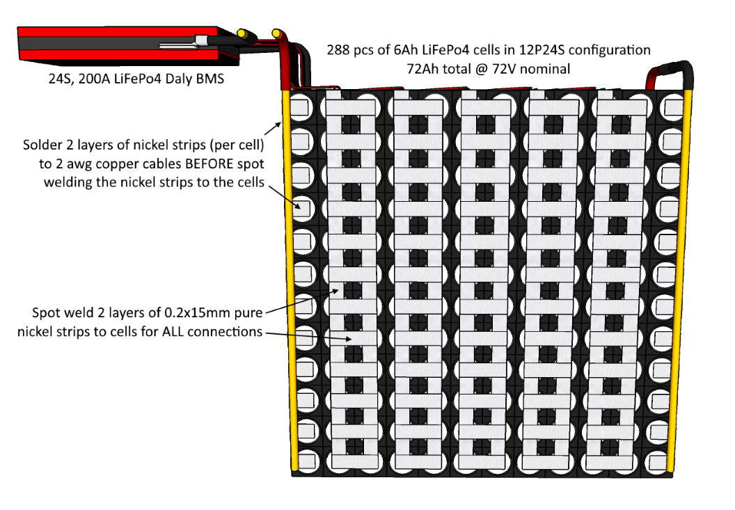
Because Grepow doesn't sell batteries directly to the general public, I recommend using 6000mAh LiFePo4 cells from batteryhookup.com to build your own battery like the one shown below that I designed to work with this bike. With a 12P24S configuration, you'll get 72Ah of capacity @ 72V, with 180A of continuous discharge current (720A peak) and a 72A (1C) max charge current (~1hr charge time with the charger listed in the BOM). A perfect match for this drive system. All of the cell to cell connections should be done with 2 layers of 0.2x15mm pure nickel strips, and the series connections between the two separate packs and the BMS should be done with 2 awg copper cable to ensure all connections can safely handle the full 180A load. Where nickel strips are connected to the copper cables, they should be soldered together first, then the nickel strips can be spot welded to the cells. If you solder after, you could risk overheating and damaging the cells with your soldering iron. This is also why you should spot weld the cell to cell connections and not solder them.
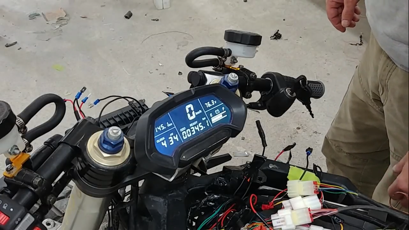
After making all the connections, I connected the controller to my PC and performed the angle identification procedure using Kelly's program (available for Android devices too). This is necessary to do in order to sync the motor with the controller. Once the procedure was finished and verified successful, I disconnected the controller form the PC and cranked the throttle to test. Everything worked fine, no problems. Time to make a seat and finish the build.
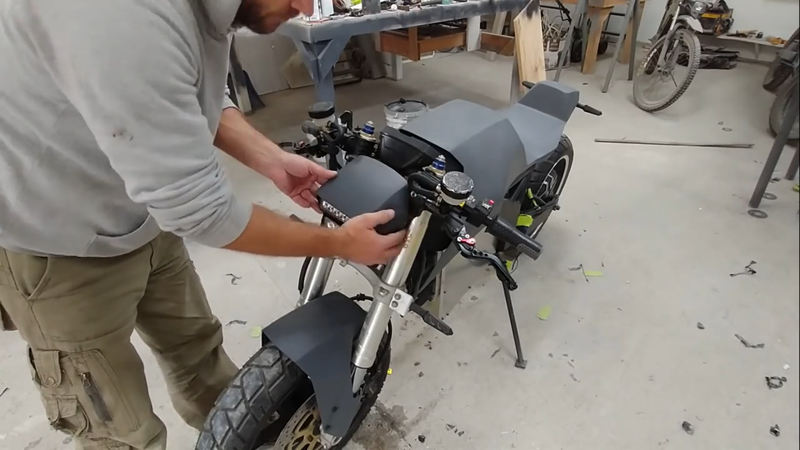
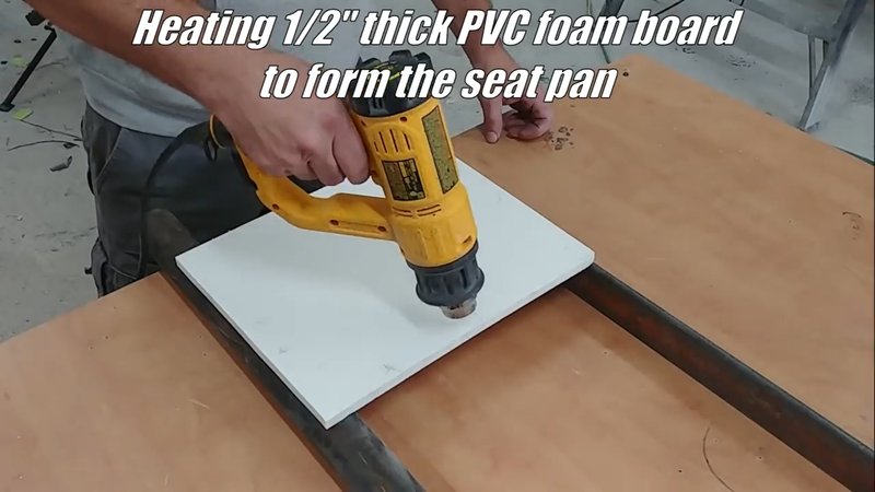
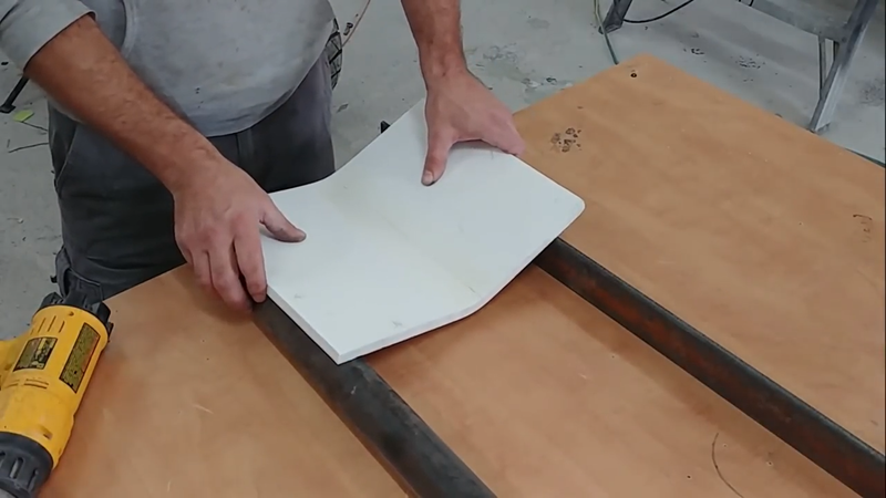
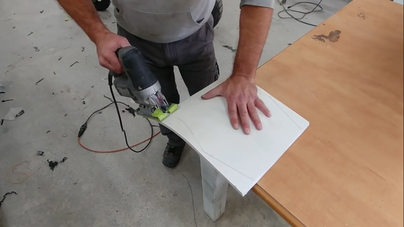
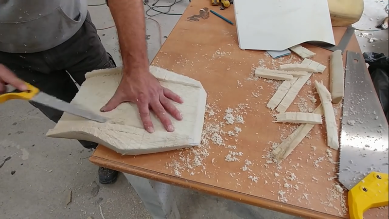
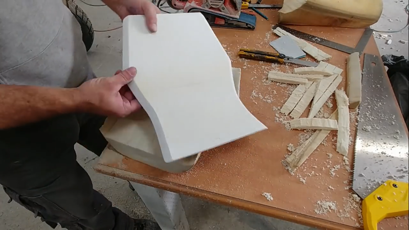
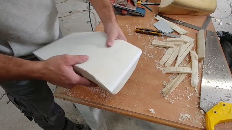
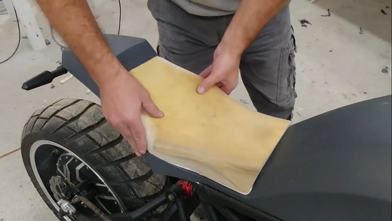
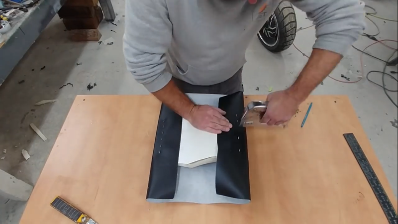
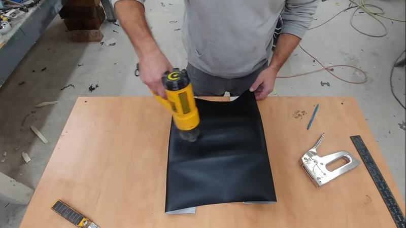
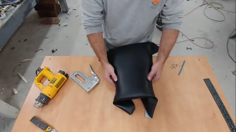
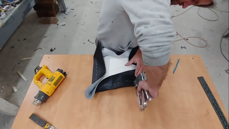
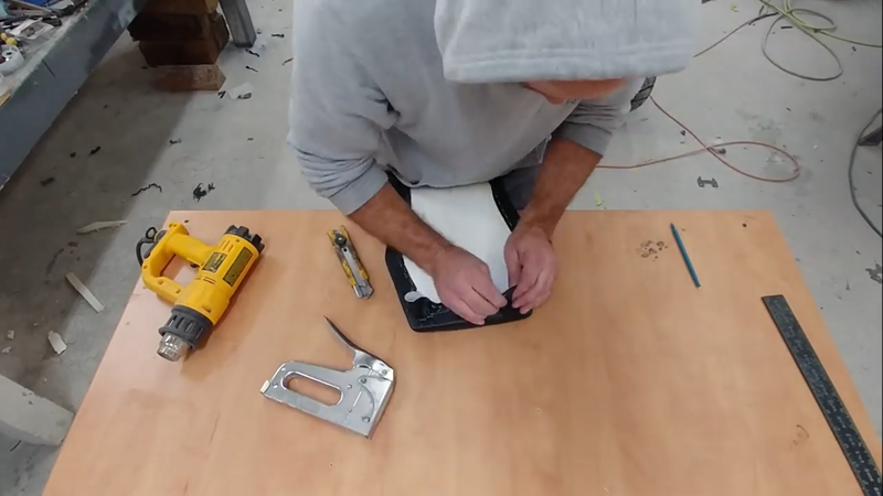
For the seat pan I used a piece of 1/2" PVC foam board. I really like this materials because it's lightweight, easy to work, and easy to fasten seat cover material to with staples, but it's also very strong. I used a heat gun to heat the PVC and shape it to the profile of the bike, then trimmed it to size. The cushion material - recycled from an old torn up ATV seat - was then shaped using handsaws and a belt sander, then I wrapped it with a vinyl seat cover. The vinyl cover is a two-way stretch material, meaning it can stretch in two directions to make wrapping around contours easier. The trick to prevent wrinkles and get the cover as tight as possible is to first fasten it to the seat pan at the front and back, then use a heat gun to heat the material in the middle where it needs to be pulled down toward the cushion. Once it's relatively warm to the touch, pull the other two unfastened sides around the seat pan tightly with equal pressure and staple them. Then work each corner, starting in the apex of the corner first and working toward the sides. There will always be wrinkles on the bottom side, but as long as they're kept small/thin then the fit will be fine.
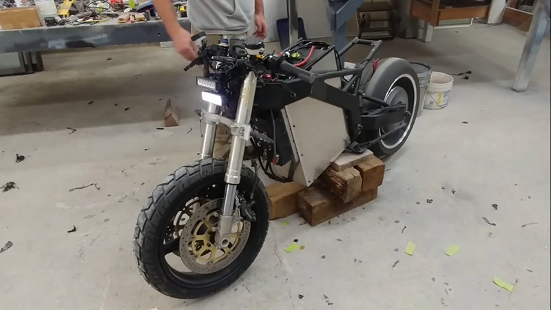
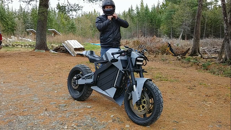
The seat was then screwed to the fairing through the bottom, and it was time to go for a test ride! Which went well. The suspension needs some fine tuning, as to be expected, but other than that I couldn't be happier with how it turned out. For the sake of economics, I did a cost benefit analysis and posted the details below.
ROI breakdown:
Cost of electric bike build = ~$5000 total Nominal battery capacity = 4.3 kWh Life span of LiFePo4 cells = ~5000 cycles Range per charge = ~80km @ 80% DOD (up to 100 km @ 100% DOD) Local grid energy cost = $0.12/kWh Cost per charge (100 km) = 0.12 * 4.3 = $0.52 Cost per km for energy = 0.52 / 100 = $0.005 Avg price of gasoline in Canada = ~$1.00/ liter Energy in 1L of gasoline = 8.9 kWh Fuel economy of the most efficient petrol bikes = ~60 miles per gallon, or 25.5 km/L Cost per km for fuel = 1 / 25.5 = $0.04 Electric bike energy cost savings per km = $0.04 - $0.005 = $0.035 Savings per charge/cycle (80 km) = $0.035 * 80 km = $2.80 Payback period based on full cycle charges = $5000 / $2.80 = 1785 cycles OR Savings per day based on driving an avg 40 km per day as a daily commuter = $2.80 / 2 = $1.40 Payback period = $5000 / $1.40 = 3572 days, or 10 years. 5 years if driven 80 km per day.
37 Comments
Himanshu Rabha
7/21/2021 01:15:37 pm
I'm in love with your project, i would like to tryout making one for myself, but its its nearly impossible to find the materials here in our place...mainly the electronic components......bytheway it was a great build, best of luck for your upcoming projects...
Reply
Ankit Chauhan
2/3/2022 04:19:39 am
Hi i am working on new E vehicles project in India i am trying to collect funds i have 5years experience in EV I'm from mechanical engineering department
Reply
Davis Junga
7/23/2021 10:43:38 am
Hi it's was great watching the rebuild video and it was one of my Best video, great job...
Reply
Joe
7/28/2021 06:51:36 am
Really nice project. Wish i could build one
Reply
Praveen
8/8/2021 01:13:35 pm
Sir i can't find that motor and battery.... Like you used in this project street fighter bike.... I love that
Reply
Manny
10/5/2021 08:58:17 pm
I also would love to know where or what websites I can buy the same components as you do . If you can much a appreciated.
Reply
Vedaant kapoor
8/14/2021 05:04:46 am
How do I get in touch? Let’s do some business.
Reply
Gagandeep Singh
8/15/2021 01:12:30 am
hi i want to buy this one is it possible to buy from you ??
Reply
mayuresh mandge
8/15/2021 02:38:54 pm
i want that body of the bike and battery to build one ,
Reply
Mhehedi Hasan
8/16/2021 10:56:51 am
Can I buy it??🙂
Reply
amal
8/29/2021 01:49:31 pm
really love this. r u making more for selling. im interested to buy this street rider. <3
Reply
Flávio Pedro Wildchen
9/4/2021 06:00:27 am
Oi, alguém pode me vender ela pronta?
Reply
Stephen Parkinson
9/9/2021 04:16:58 pm
Just finished watching this project and reviewed the build site. I have an existing motorcycle chassis for an 87 GSXR. Is there a reason you chose to fabricate one from scratch versus using existing?
Reply
vishal sartan
9/29/2021 02:17:35 pm
Hello,
Reply
Manny
10/5/2021 09:01:16 pm
I also would love to know where or what websites I can find to buy the same electronic/electric components as you do . If you can much a appreciated.
Reply
Augusto
11/5/2021 09:40:41 am
How many time is needed to complete the charge?
Reply
Gianluigi Sartori
12/18/2021 07:36:06 am
Question:
Reply
David Spady
12/30/2021 04:24:37 pm
Hi,
Reply
jack
1/6/2022 04:07:25 pm
can i order from u 1 like this ?
Reply
Ayirwanda Adolphe
1/14/2022 02:33:53 pm
I want to buy this bike
Reply
2/15/2022 07:32:36 pm
I'm very interesting to do like this.
Reply
3/22/2022 09:37:13 am
I'm very interesting to do like this.
Reply
darren Steven laporte
4/25/2022 08:34:57 pm
i want a bike just like this. i live in new york city, how much total to ship? and how long do i have to wait to get it?
Reply
Holger Janssen
5/3/2022 01:34:31 pm
Super sache.Wollte auch eine aufbauen aber als bobber.Jetzt fahre ich ein suzuki bandit 1200 s aber mit meinen 55 jahren kracht es in den knochen und nun solls ein bobber werden. wal sehen ob ichs mache .
Reply
John Muthini
6/26/2022 05:25:14 am
Can you sell it to me?
Reply
Deen
12/13/2022 02:40:30 pm
Is it for sale
Reply
3/21/2023 06:28:00 pm
Wow, what an impressive feat to have built an electric motorcycle from scratch! Your post provides a fascinating insight into the intricate details of designing and constructing an electric motorbike, from sourcing the parts to troubleshooting the electrical system. It's inspiring to see how you overcame the challenges and setbacks that came your way, and ultimately succeeded in building a working motorcycle that's both environmentally friendly and high-performing. Your passion and dedication to this project shine through in your writing, and I'm sure it will inspire others to take on similar DIY projects. Well done!
Reply
4/17/2023 05:09:01 am
copper cable to ensure all connections can safely handle the full 180A load. Where nickel strips are connected to the copper cables, they should be soldered together first, then the nickel strips can be spot welded to the cells. If you solder after, you could risk overheating and damaging the cells with your soldering iron
Reply
6/13/2023 01:03:37 am
I appreciate how the author presents the information in a clear and concise manner, making it easy to follow and understand. additional learning to your article. thanks
Reply
8/21/2023 09:14:00 am
You can supply steel square profile and rectangular profile at reasonable prices.
Reply
Victor
4/20/2024 03:47:09 am
I have a similar bike but built from China. One day, I noticed that the throttle no longer works and I got an e-bike tester to troubleshoot it and it shows the throttle is working. I also tested the brakes and they are working. Can you help with the troubleshooting?
Reply
Leave a Reply. |
AuthorJames Biggar Archives
March 2023
Categories |


 RSS Feed