Hi folks. In this video I show and explain how I built a custom battery & enclosure for my new kWeld DIY spot welder that I purchased from Keenlab. If you're interested, you can find the .stl files for 3d printing the custom enclosure below, along with links for the kWeld spot welder and 38120 battery cells that I used. The enclosure requires #6x5/8" screws to assemble.
Where to buy the welder (authorized distributors)
North America: https://gridrewired.com/products/kweld-spot-welder-kit
UK: https://ecyclerevolution.co.uk/product/kweld-complete-kit/
Australia: https://batteryphysics.com.au/product-category/spot-welder-keen-labs/
Germany: https://www.keenlab.de/index.php/product/kweld-complete-kit/
Individual 38120 cells:
https://batteryhookup.com/products/used-headway-38120-hp-3-2v-8ah-lifepo4-battery
38120 cells in modules w/ bus bars, screws, holders, etc.:
https://batteryhookup.com/products/kit-only-6000w-12v-48ah-614wh-busbar-holders
| kweld_back_panel.stl |
| kweld_front_panel.stl |
| kweld_back_cell_holder__1_.stl |
| kweld_front_cell_holder__1_.stl |
| kweld_switch_bracket.stl |
| kweld_front_bracket.stl |
| kweld_top___bottom_panels.stl |
| kweld_feet.stl |
| kweld_back_cell_guard.stl |
| kweld_front_cell_guard.stl |
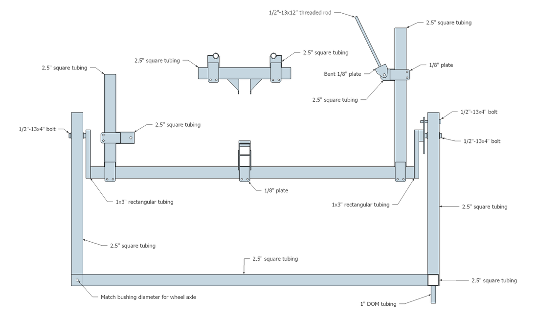
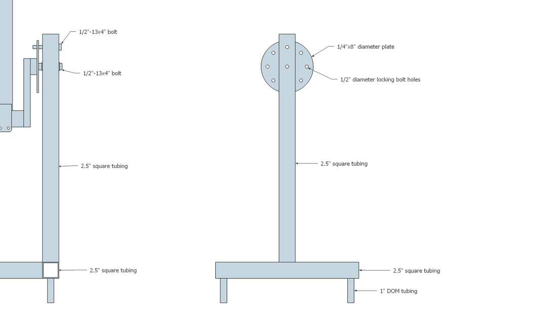
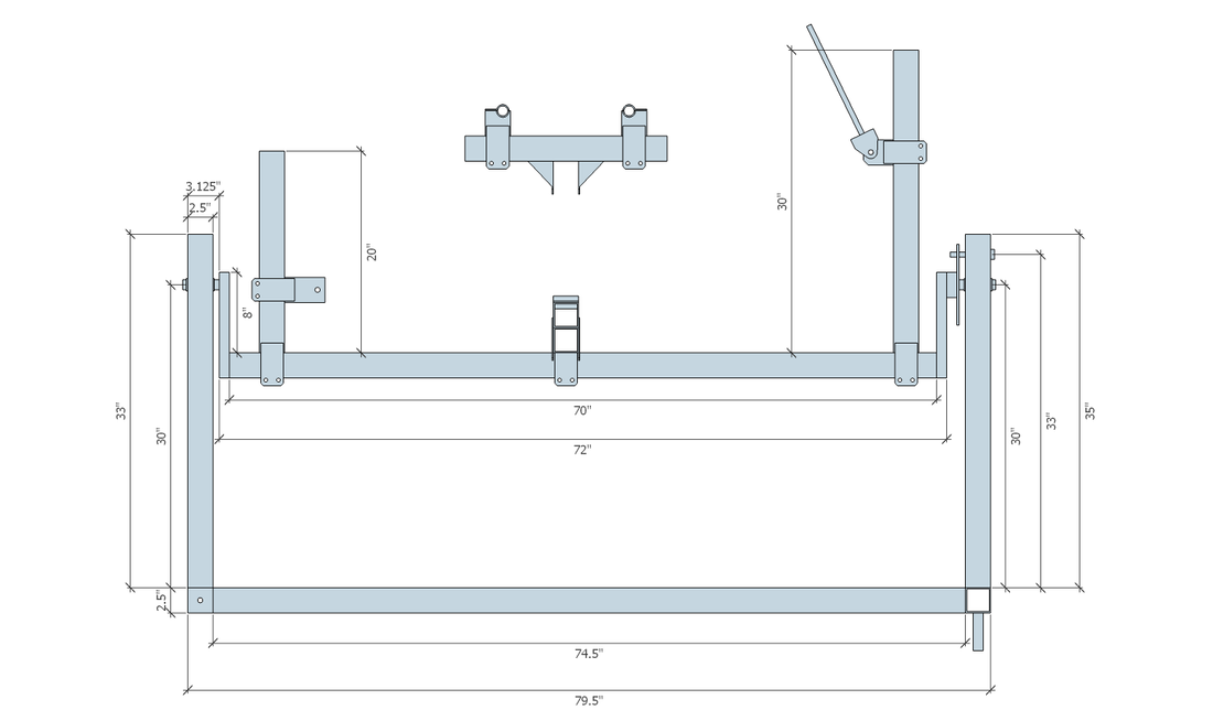
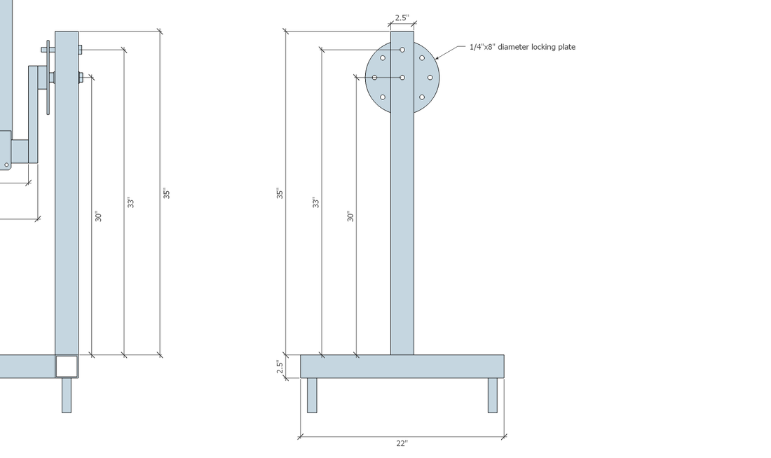
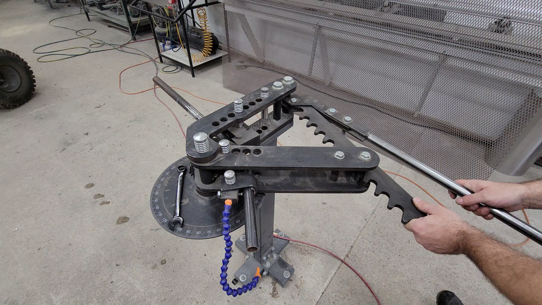
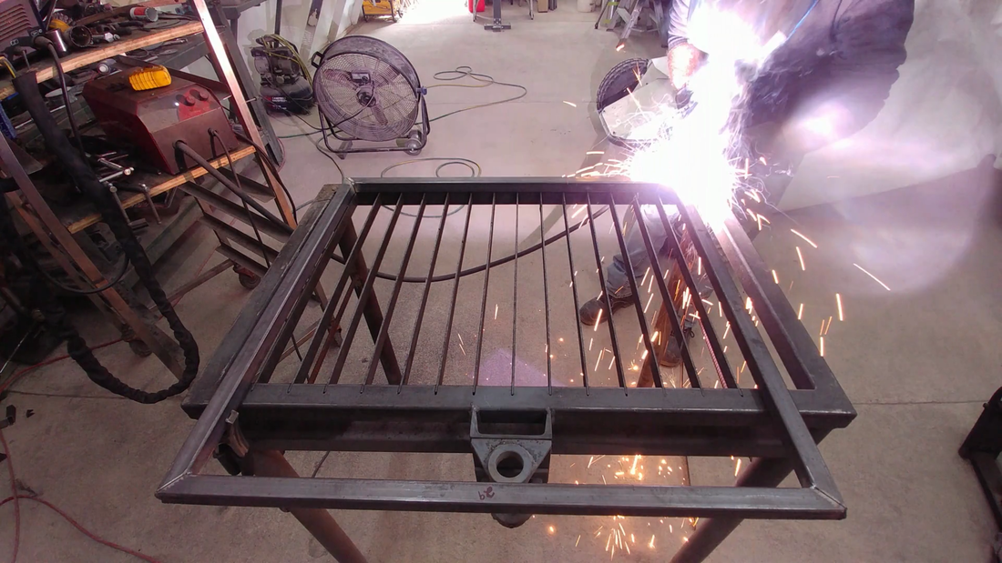
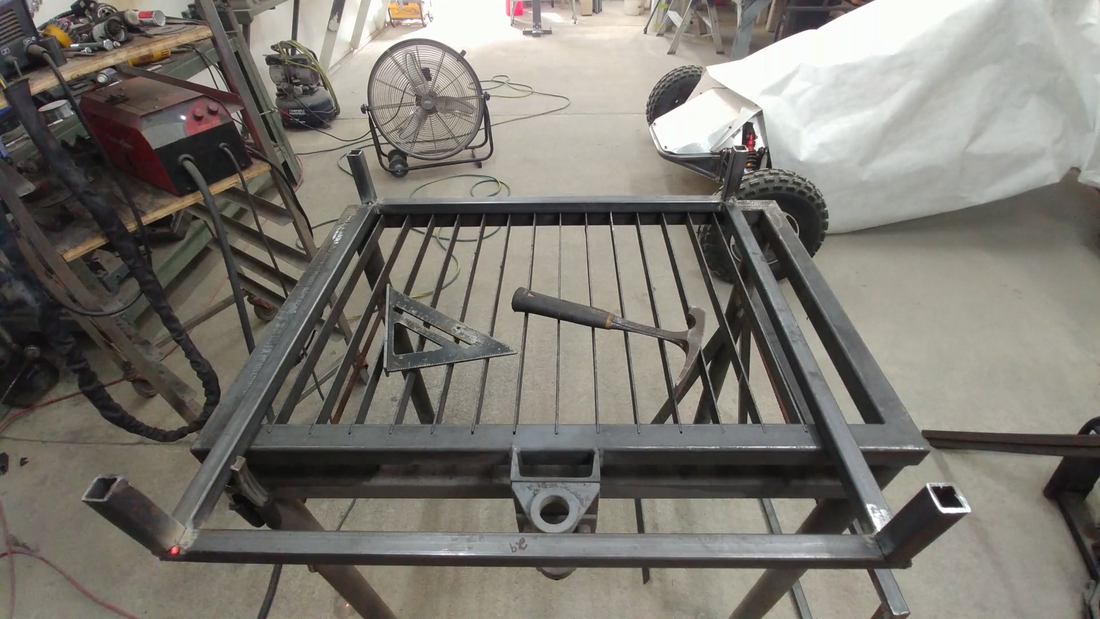
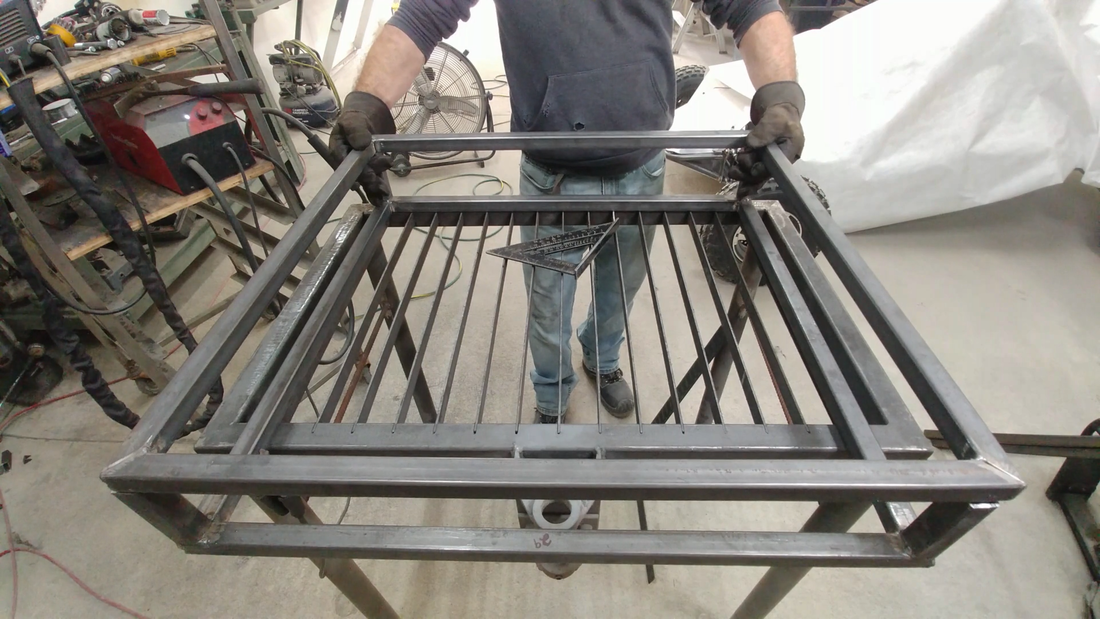
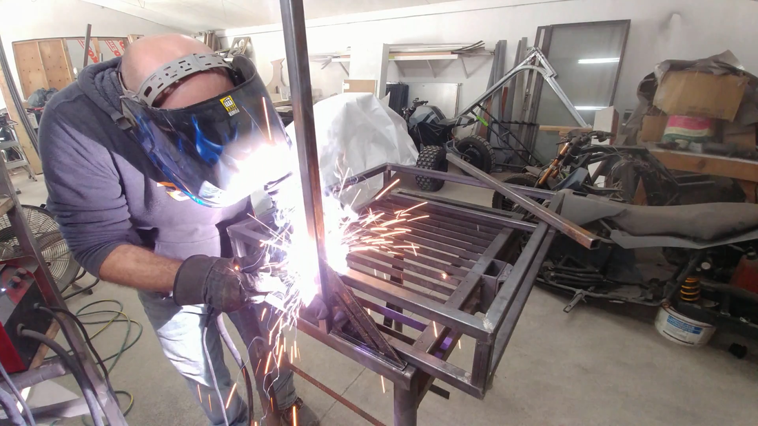
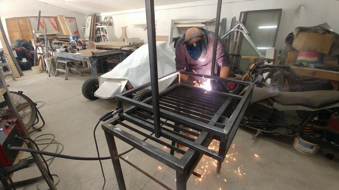
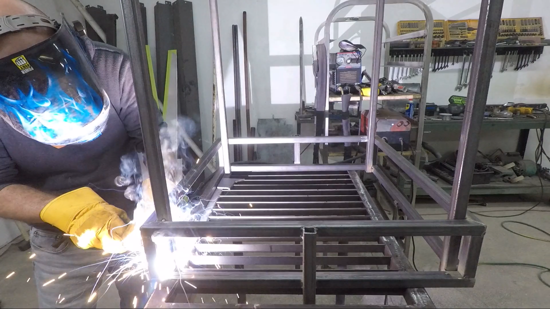
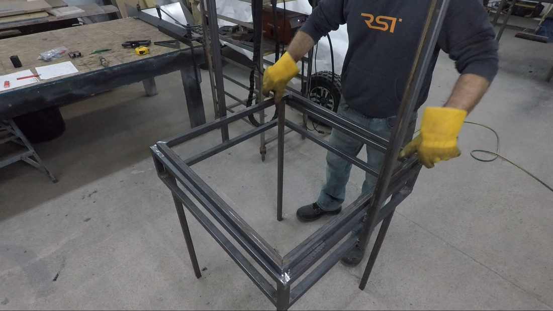
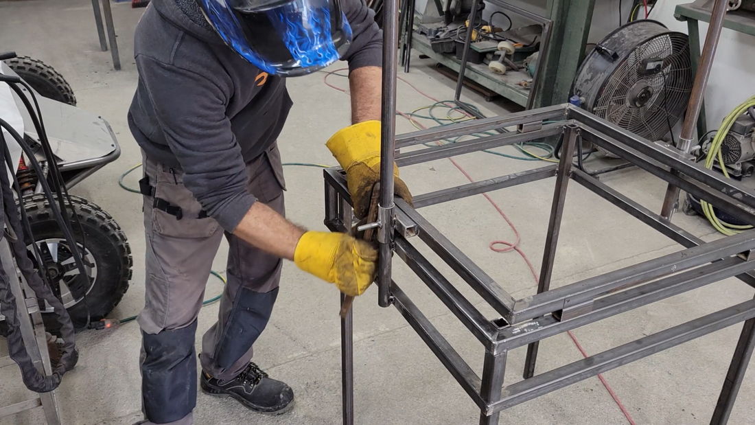
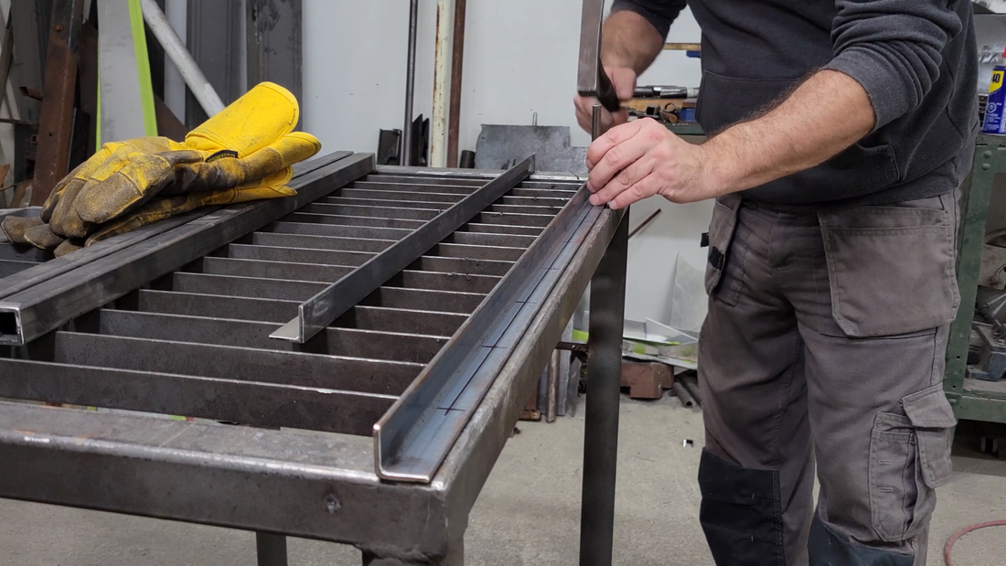
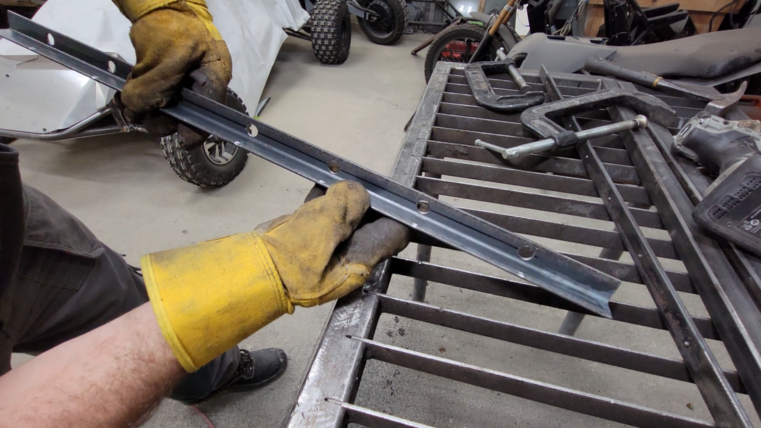
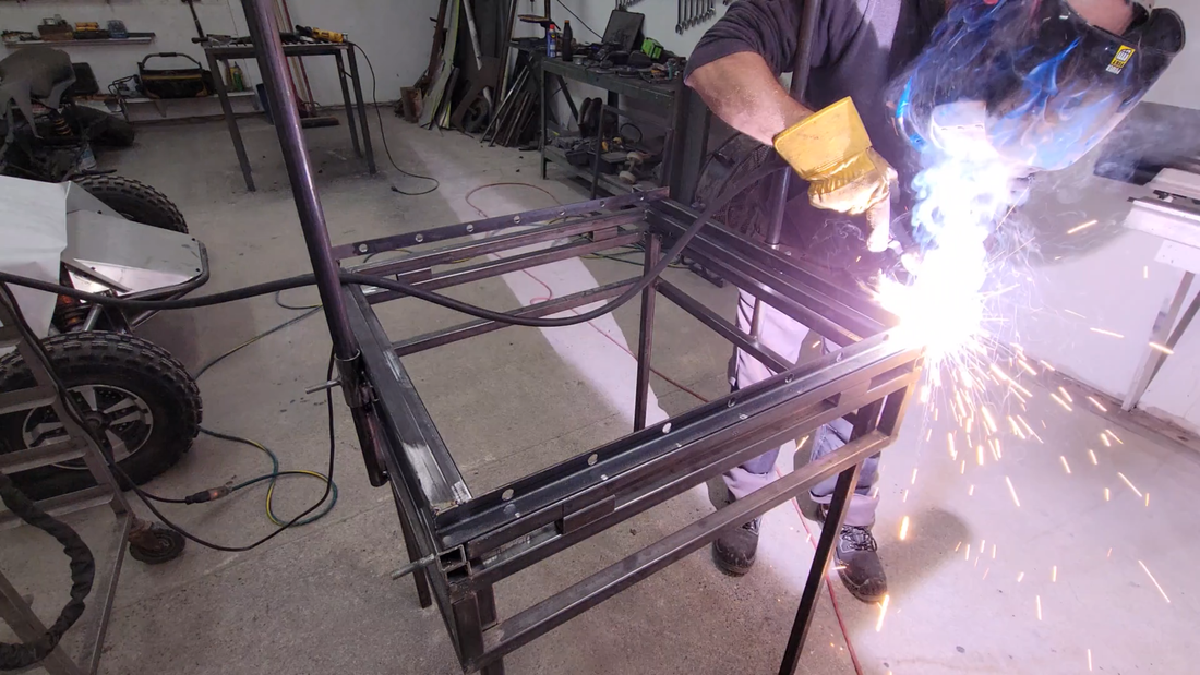
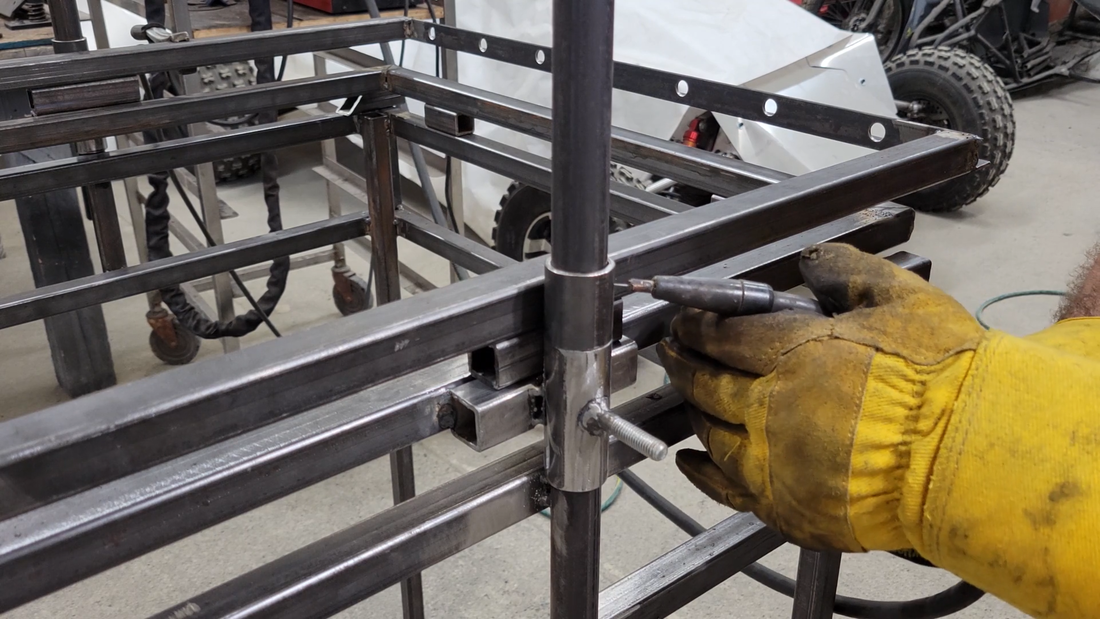
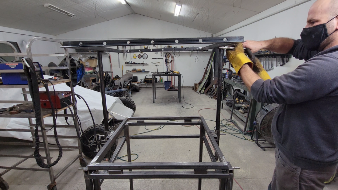
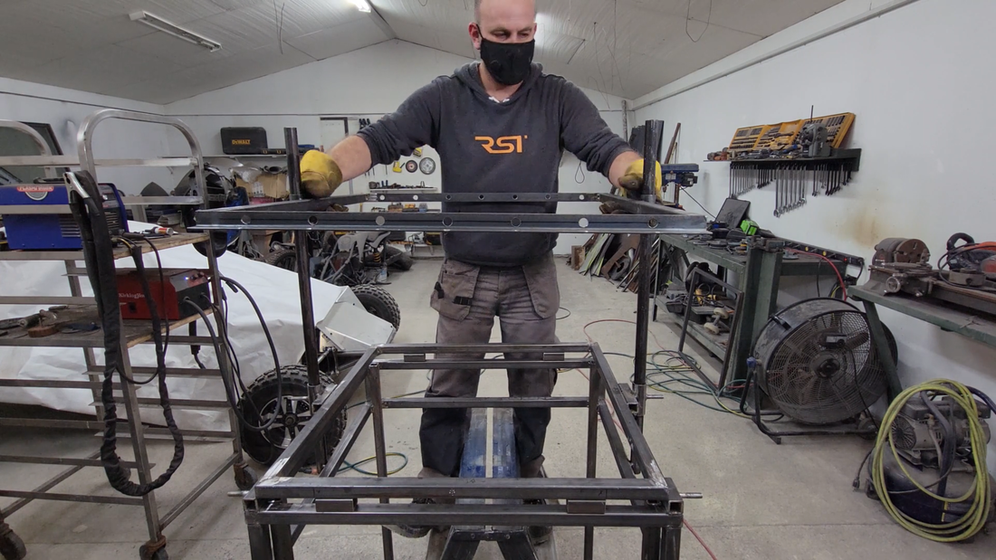
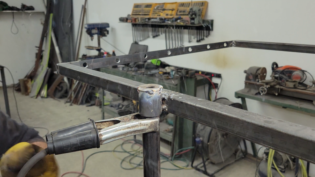
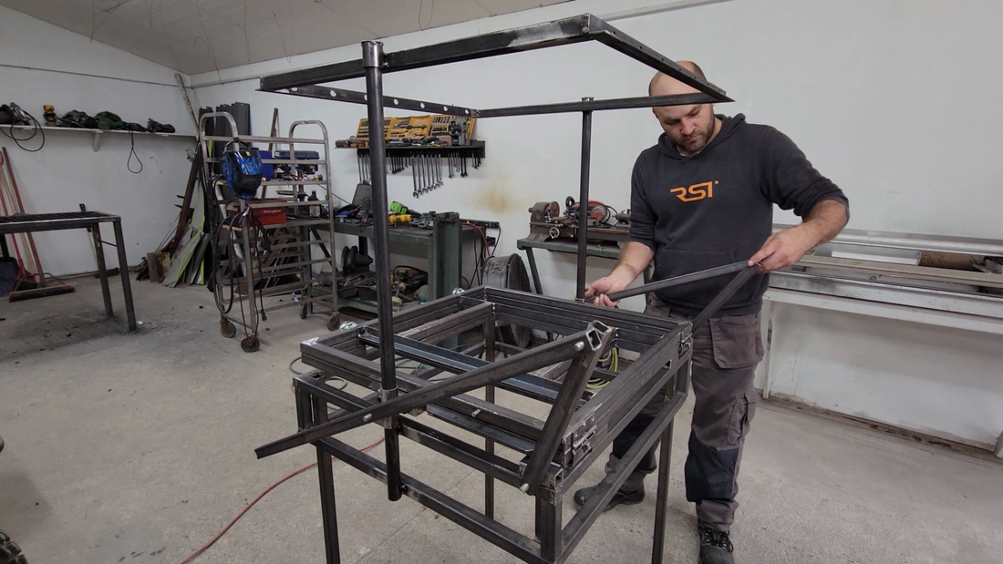
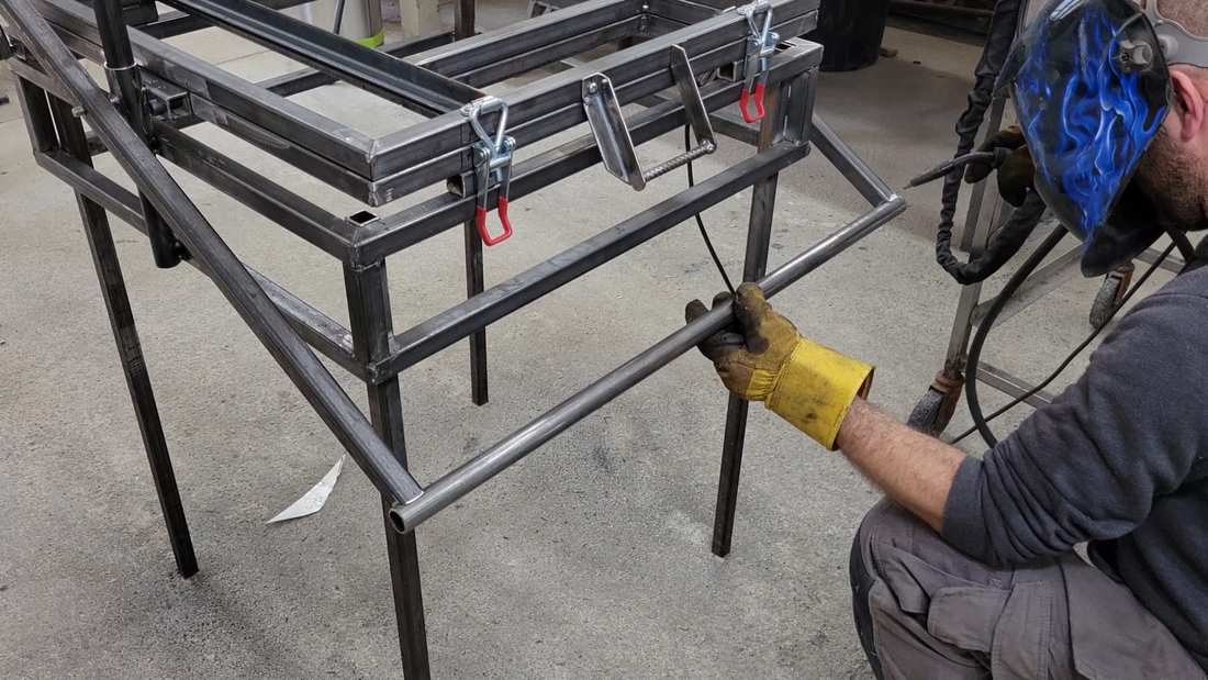
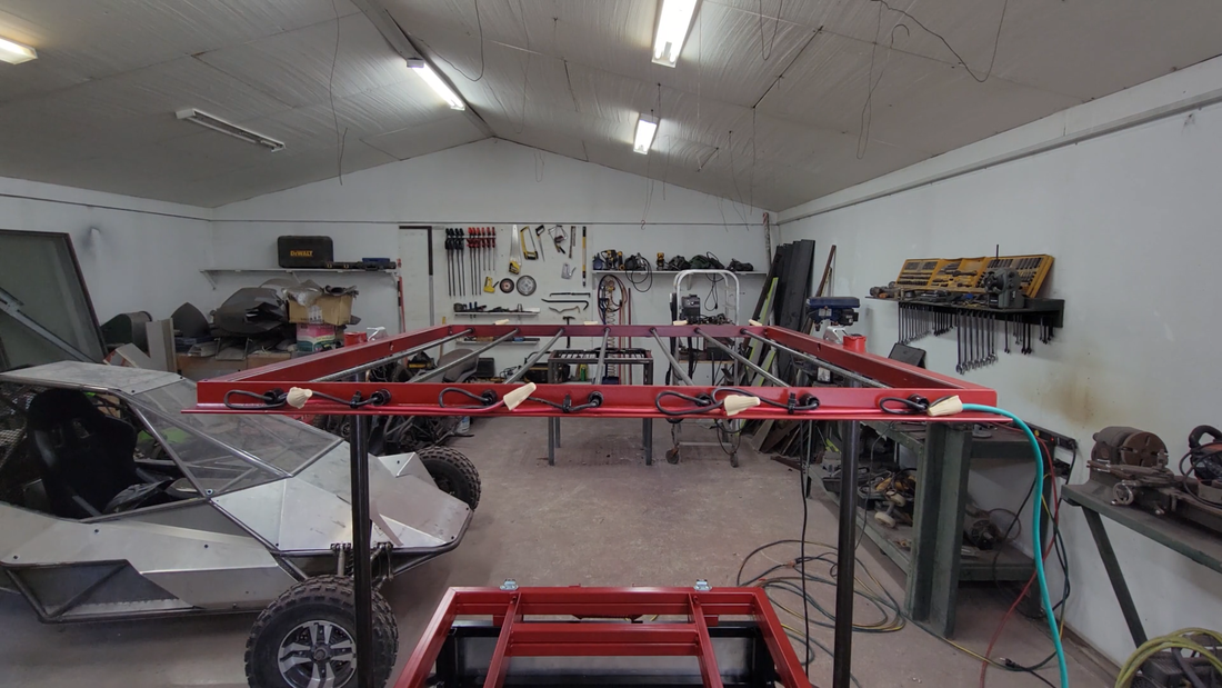
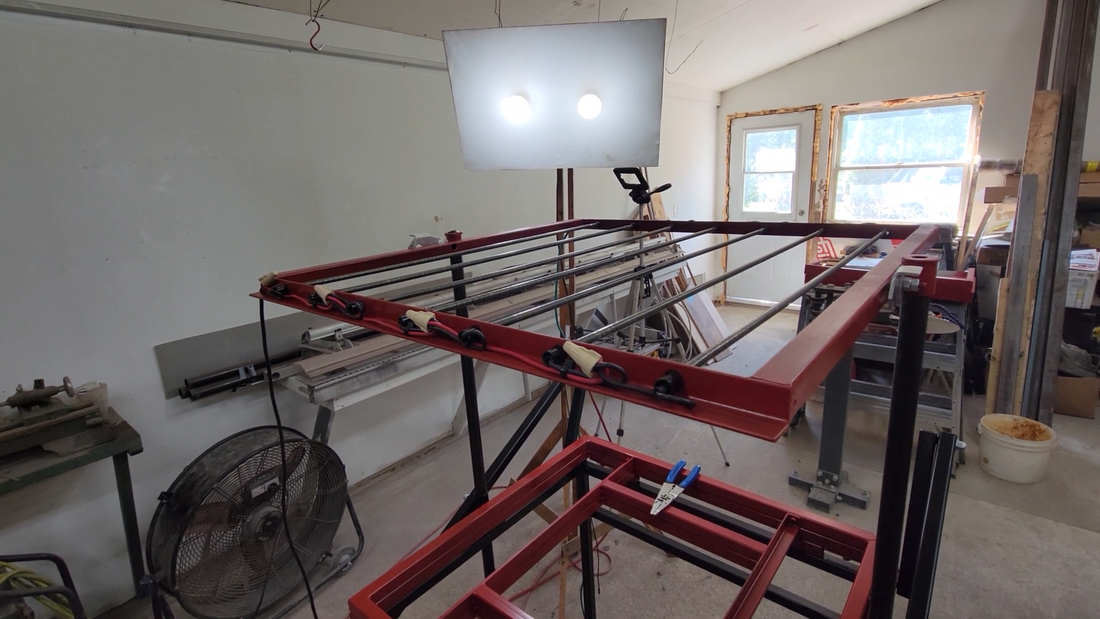
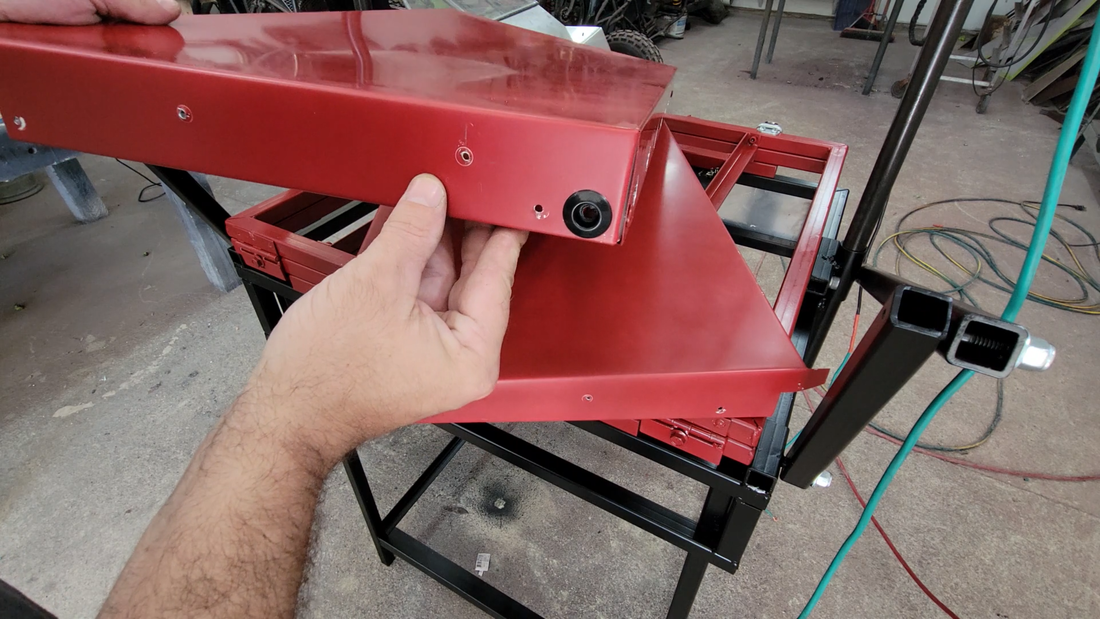
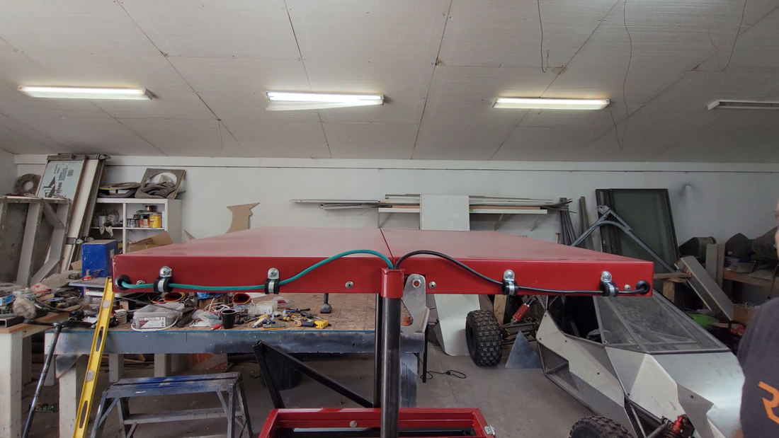
In this video I build a rotating motorcycle chassis jig. Two electric motorcycle builds are following this immediately so if you're interested in seeing them then make sure to subscribe to the channel. Free plans for this jig can be found below.
free plans:
| chassi_jig_plans.pdf |
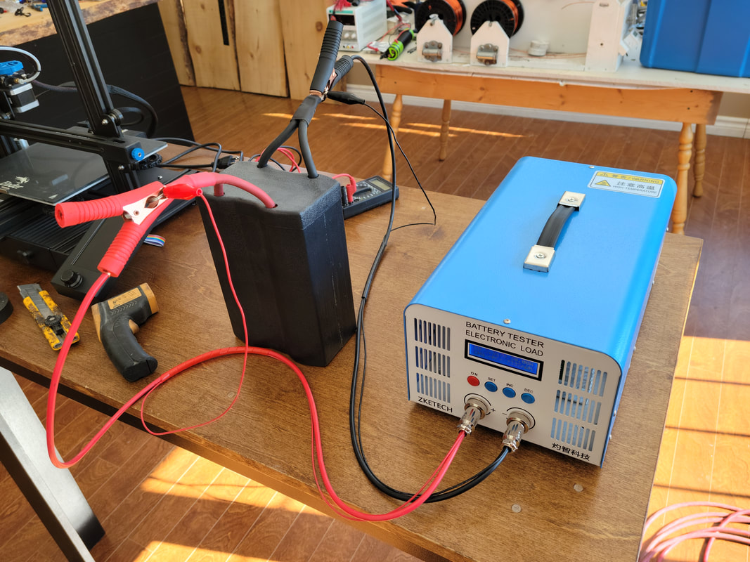
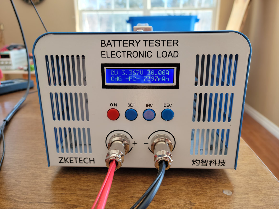
I started balancing the battery modules yesterday to prepare for installation. I'm using the EBC-A40L from ZKETECH. It comes with software that has loads of features for doing all kinds of battery testing and data logging.
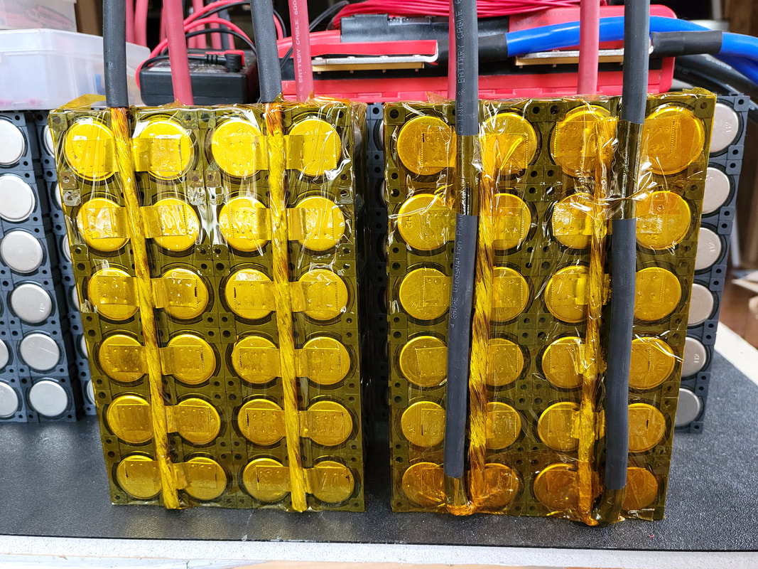
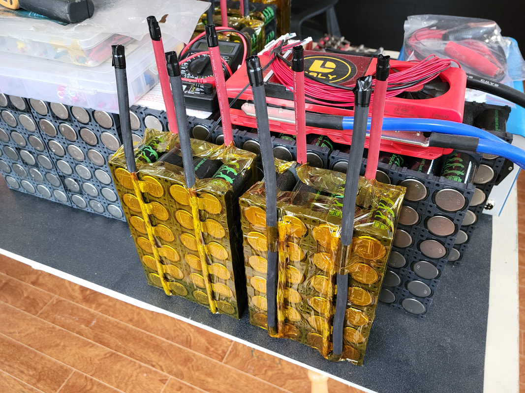
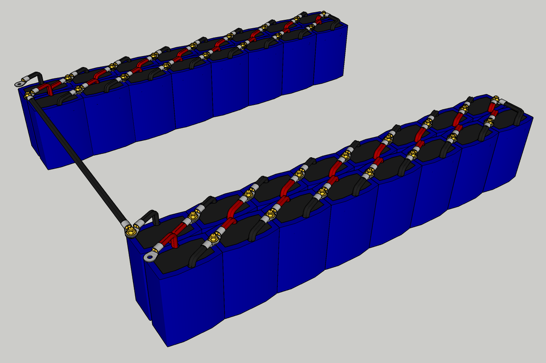
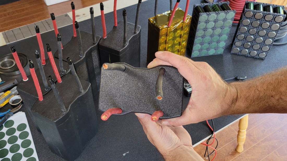
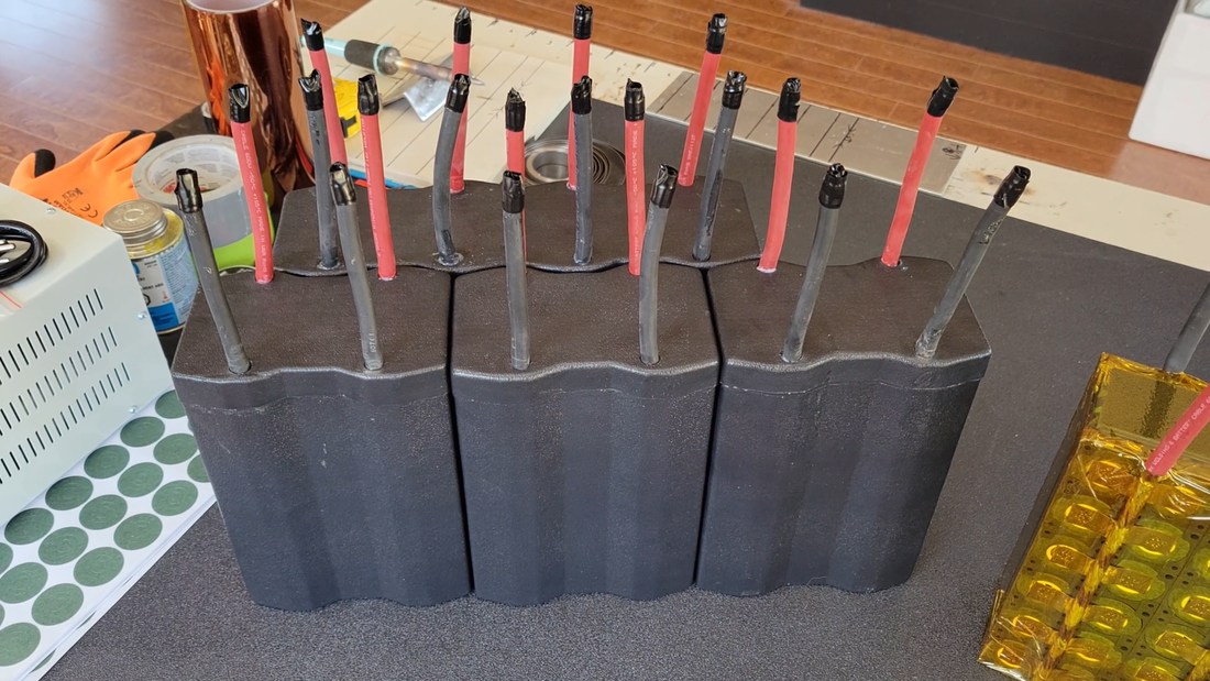
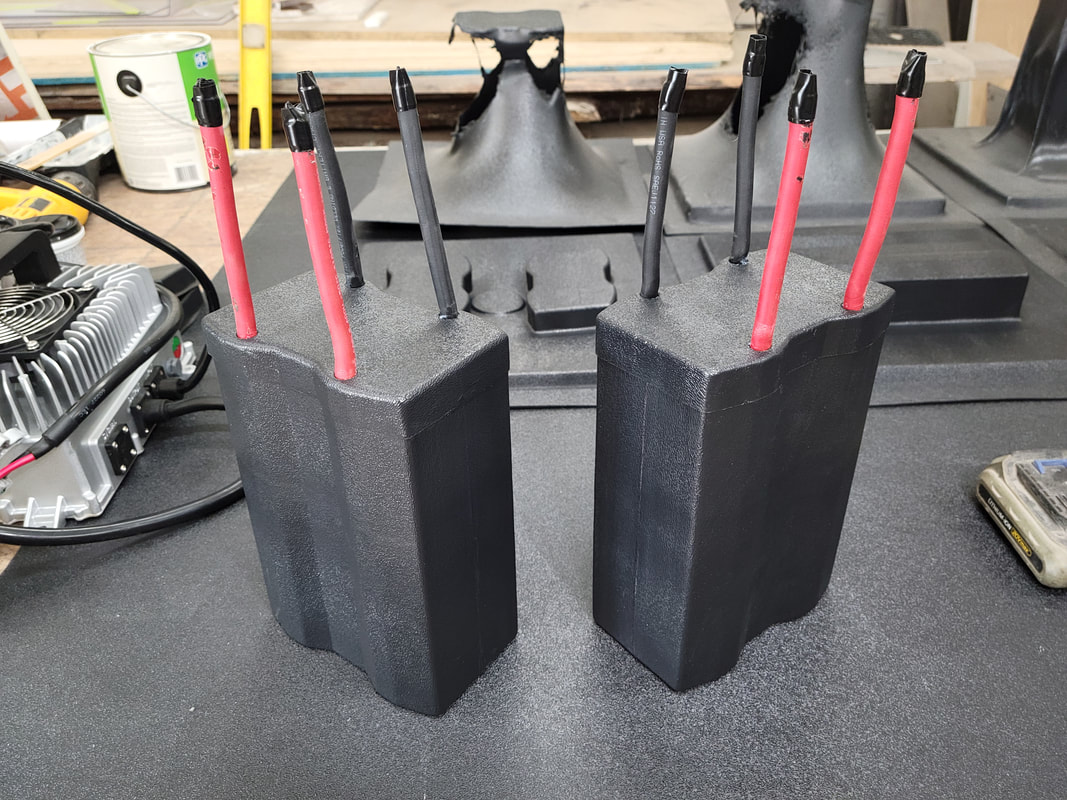
As some of you know, I made a change to the module wiring since the battery build video. Previously, I had both positive and negative cables attached the same, exiting the module at the top. Because electricity tends to take the path of least resistance, this wiring would have forced the top cells to handle most of the load when charging and discharging while the other cells slowly try to equalize on their own, and eventually the top cells would need to be replaced sooner than the bottom cells. To fix this, I spun the negative cables around so that they exit the module at the bottom cells to force current to flow from top to bottom. Two of the pics below show the old wiring (left module) and new (right module).
Atm I'm topping up each of the cells individually and putting them through a couple of full discharge and charge cycles to test capacity. Then I'll connect them in parallel and cycle them a couple more times before disconnecting them and bottom balancing individually. Basically, that involves discharging the cells to around 2.7V, stopping the discharge and waiting 24 hrs for the voltage to rise, then repeat until the resting voltage stays at 2.7 24 hrs after discharging. I'll do this with each cell and then they'll be balanced and ready to go in the kart and connect with the Daly BMS, which will take care of the balancing from then on.
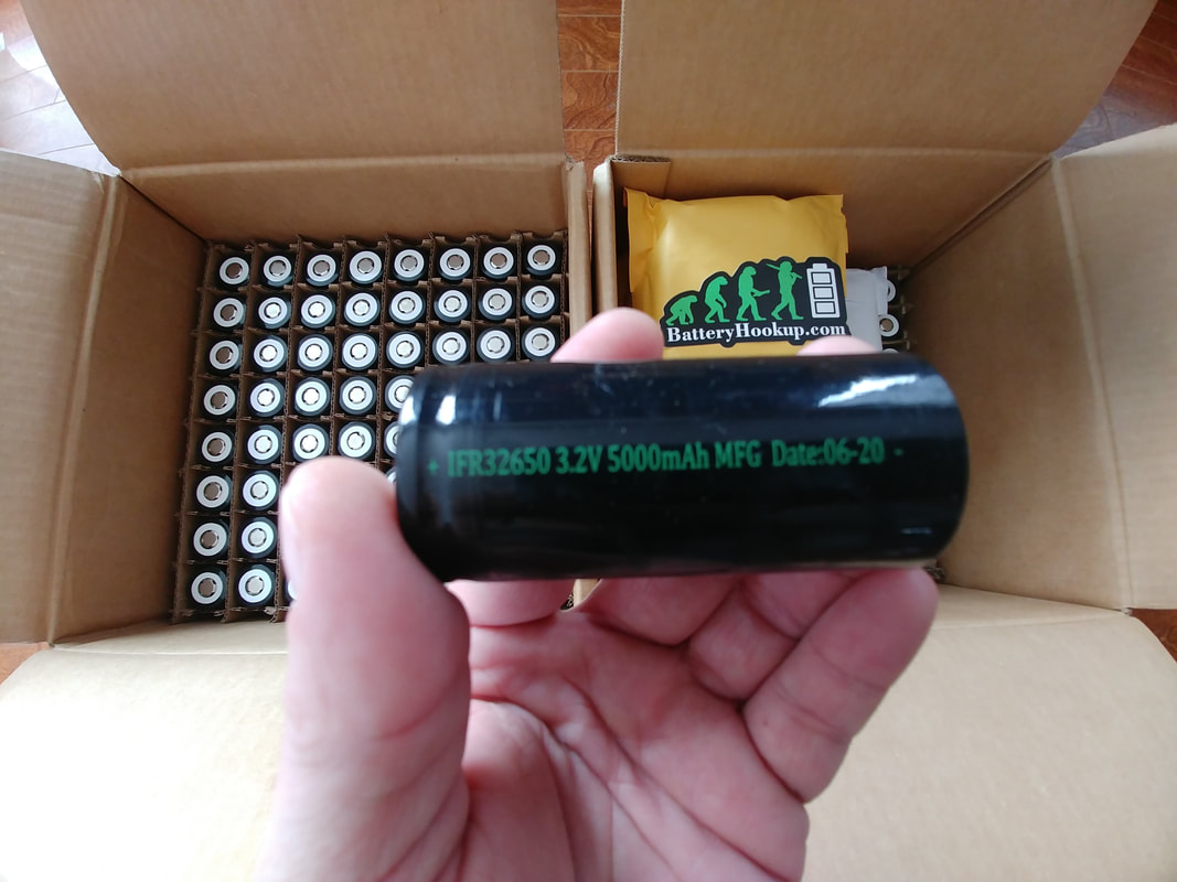
The chart below shows the discharge and charge curves for one of the battery modules. The modules are discharging at least 139 Ah (445 Wh) from ~3.45V down to 2.65V, a lot more than what I was expecting. I purchased the 32650 cells from Battery Hookup as 5000 mAh, but with 139 Ah from a 24P module, that means I'm getting around 5700-5800 mAh per cell instead. That's an extra ~2 kW more than I was hoping for, so needless to say I'm pretty happy about that.
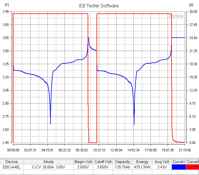
Discharge/charge curves for Battery Hookup 5000 mAh 32650 LiFePo4 cells (24P)
| battery_1_capacity_data.csv |
The EB tester software allows the user to set up a schedule to execute different tasks automatically and log the data as shown above. To cycle and test the capacity of the modules, I set my tester up to do a constant voltage charge with 30A to top up the modules to 3.65V, cutting off at 2A, and then wait for 60 min for the voltage to rest to around 3.4-3.5 (typical resting voltage for LiFePo4 chemistry) before automatically switching to constant current discharge with a 30A load down to 2.65V, then switching back again to constant voltage charge with 30A to 3.65V, cutting off at 2A. Then repeat another discharge and charge, cutting off at 3.65V and 0.1A.
The tester is a bit pricey, but I think it's a good investment for anyone who wants to do something like this (ie: build an ev). I can't imagine how long it would take to balance the modules for a battery this size using one of my little 5-10A power supplies. It would be months, at least.
The tester is a bit pricey, but I think it's a good investment for anyone who wants to do something like this (ie: build an ev). I can't imagine how long it would take to balance the modules for a battery this size using one of my little 5-10A power supplies. It would be months, at least.
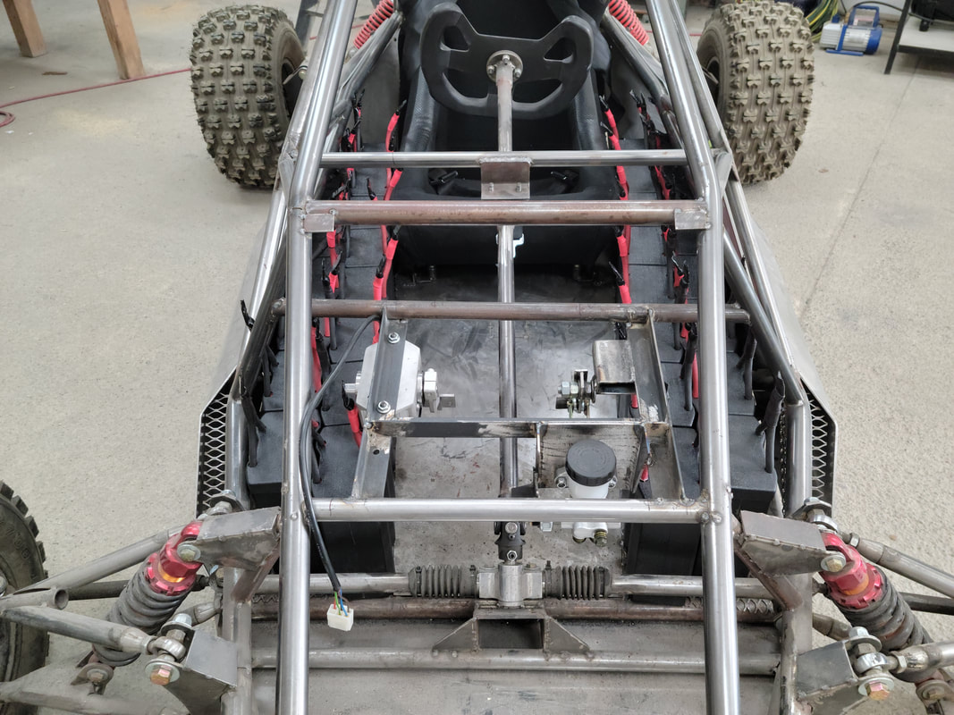
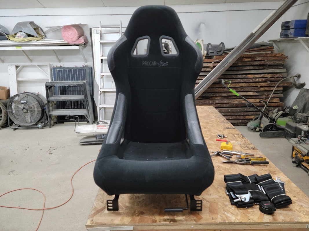
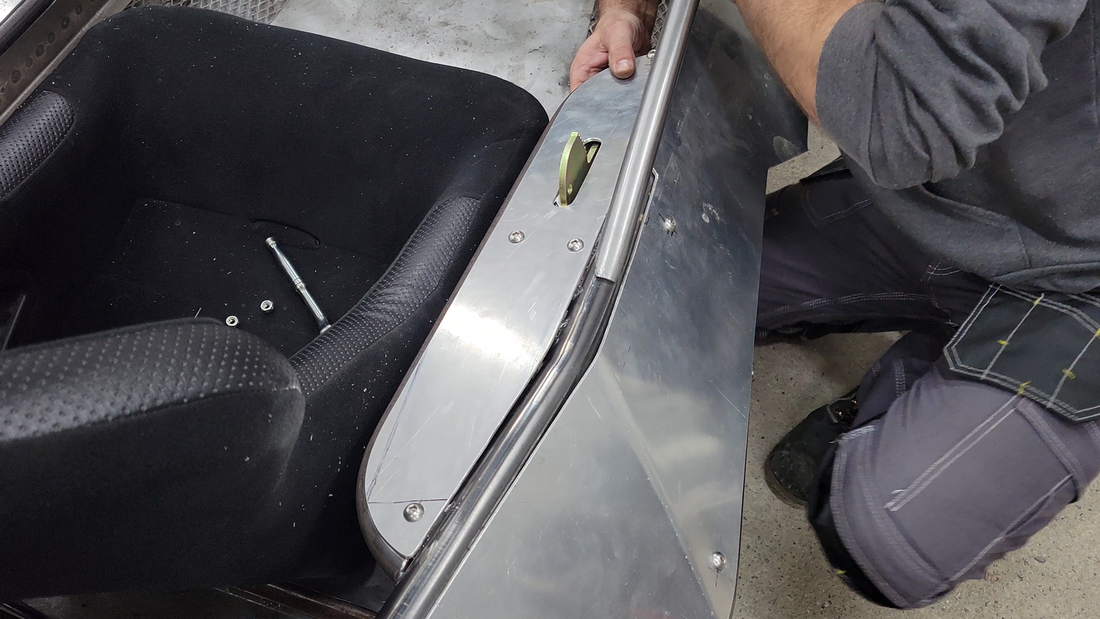
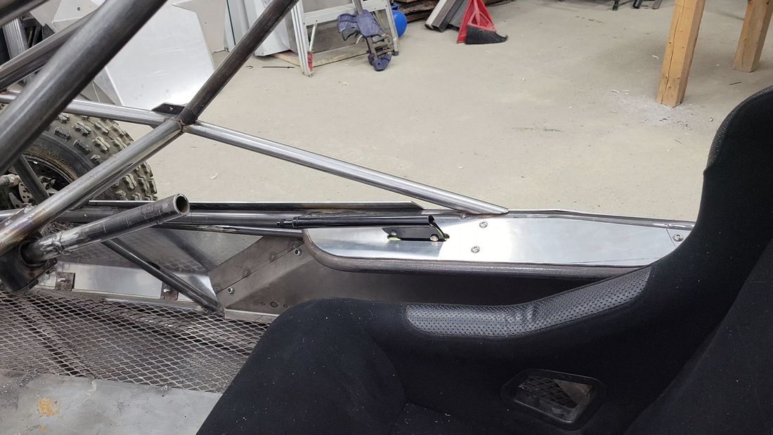
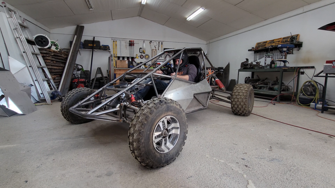
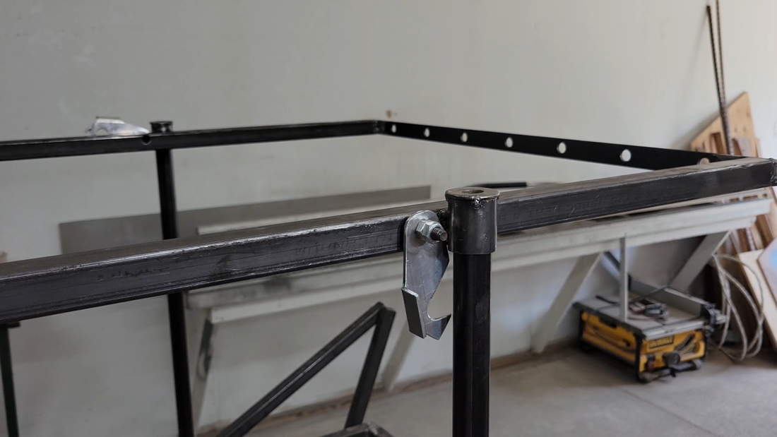
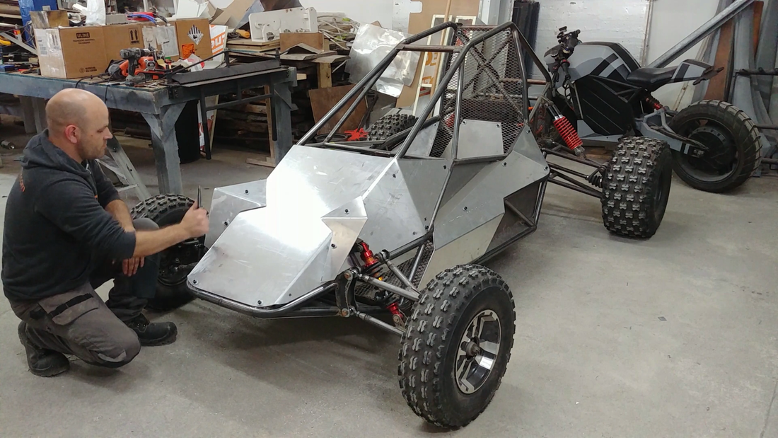
After building the battery modules, I moved on to fitting the bucket seat and parking handbrake. The seat was made by Scat Enterprises. It's designed for use with a 5 point safety harness and is as comfortable as I would expect for a racing seat. It's covered in a velour fabric which I'm not a fan of, but it's a proper seat and the most affordable I could find in the size that I needed without resorting to a plastic go-kart seat. I weigh ~180lb and it hugs my ribs pretty tight. If I were any bigger then it wouldn't be very comfortable at all, so if you're a light-heavyweight+, you're going to want to find something larger for your project (I believe these only come in one size).
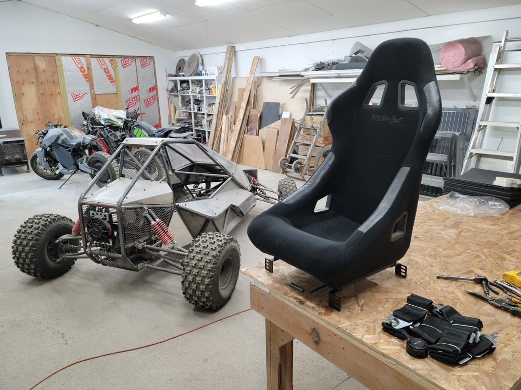
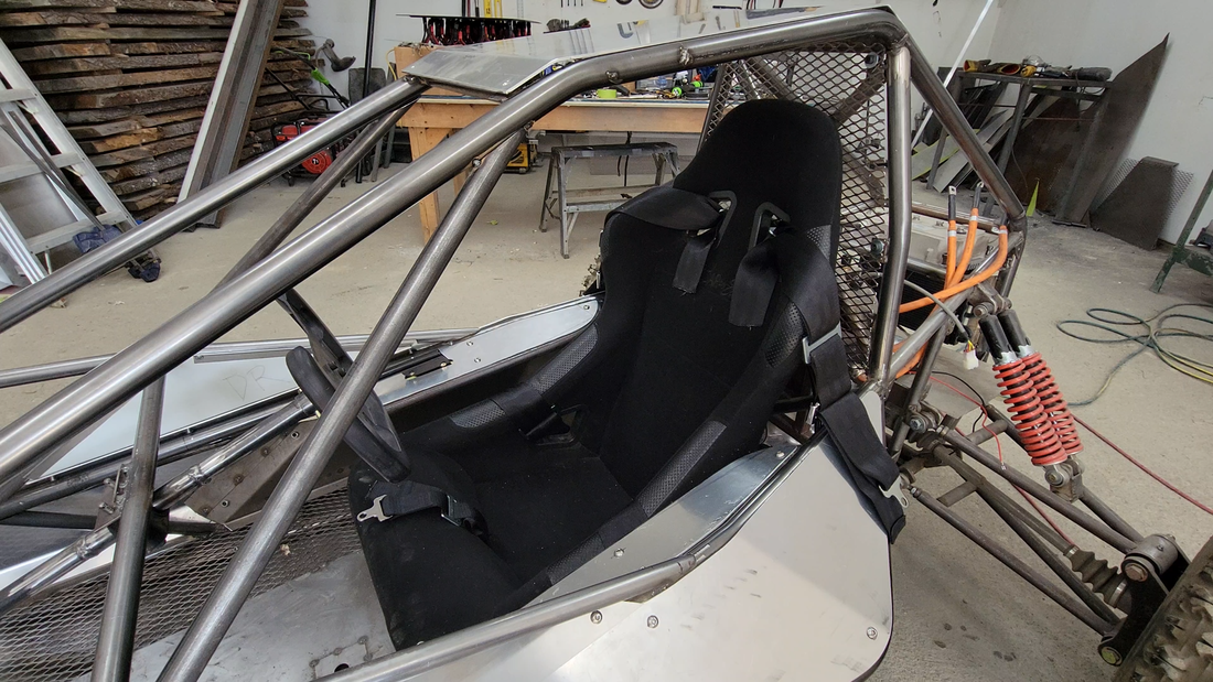
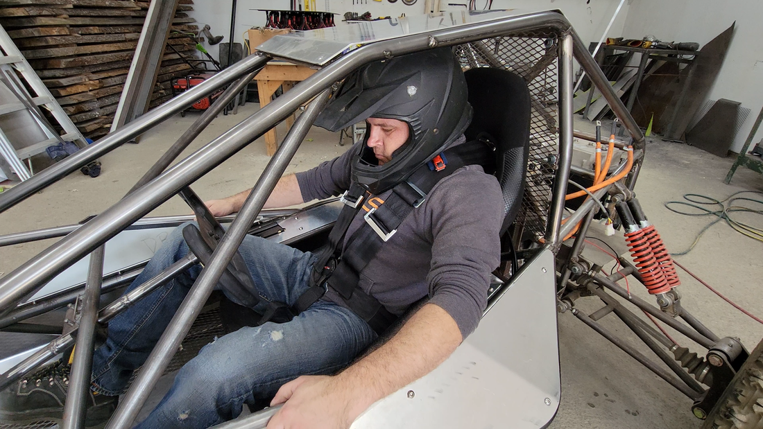
It also came with a slide track for forward/back adjustment, but it added almost 3" to the seat height and I had no room to spare, so I put the seat in the kart, jumped in and checked the leg room to determine the right location for it, then made my own fixed mounts and bolted everything to the steel plate below the floor pan. I'm making adjustments to the kart plans to add more headroom to allow for the slider and taller drivers, though.
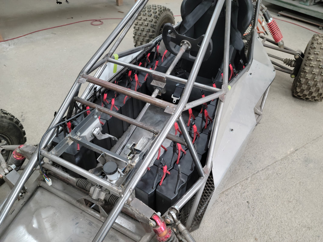
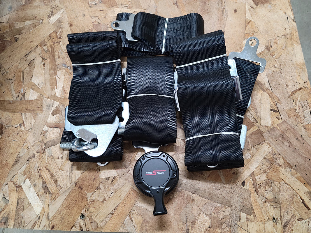
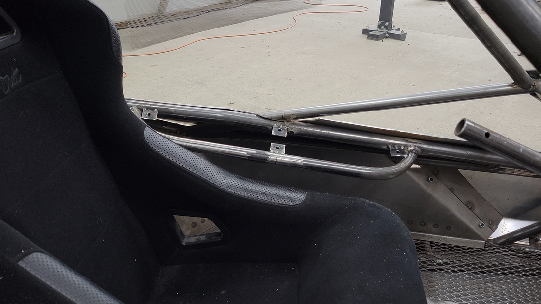
I then welded mounts for a camlock 5 point harness directly to the tube chassis. I might change to a latch and link type harness because I've heard the camlock types can get jammed with dirt when used off road.
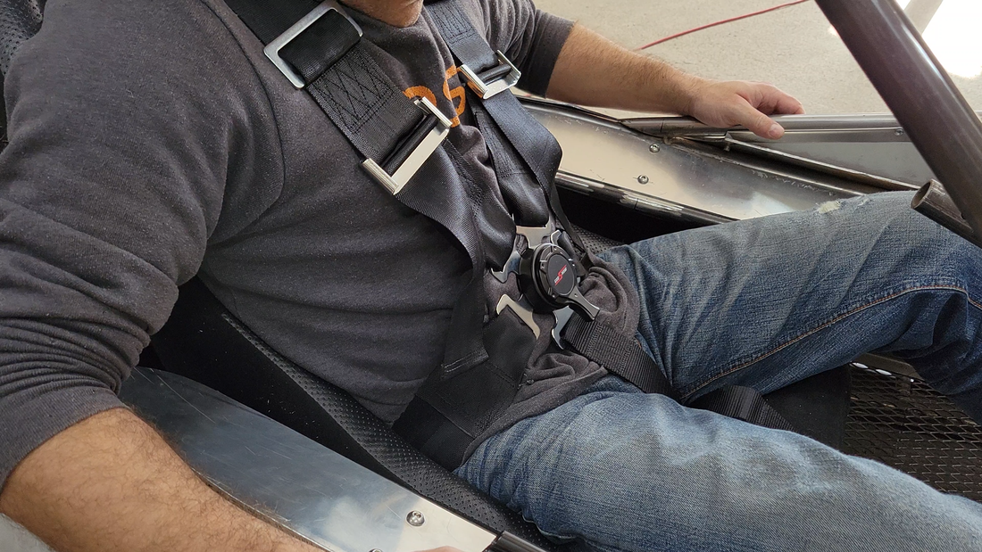
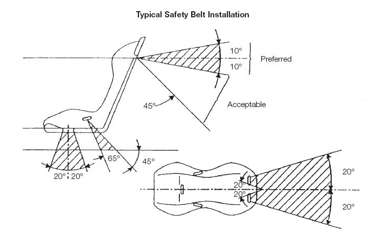
To protect my spine and keep me in the seat, the angle of the straps need to be within a certain range. The mounts for the shoulder straps are situated so that the straps are close to 90° (perpendicular) to my spine, and the waist straps are at a ~45° angle. This will ensure that the shoulder straps only put pressure on the front of my shoulders and chest to keep me from moving forward and not down on my shoulders, and the waist straps will keep my butt in the seat while keeping pressure off of my spine.
I then welded mounts for a camlock 5 point harness directly to the tube chassis. I might change to a latch and link type harness because I've heard the camlock types can get jammed with dirt when used off road.
To protect my spine and keep me in the seat, the angle of the straps need to be within a certain range. The mounts for the shoulder straps are situated so that the straps are close to 90° (perpendicular) to my spine, and the waist straps are at a ~45° angle. This will ensure that the shoulder straps only put pressure on the front of my shoulders and chest to keep me from moving forward and not down on my shoulders, and the waist straps will keep my butt in the seat while keeping pressure off of my spine.
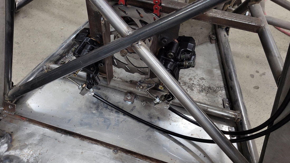
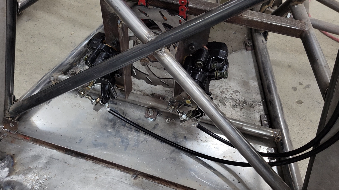
Because there's no transmission in the kart, there's also no parking gear. I used a Dodge parking brake kit to solve that problem. It came with everything I needed, from pins to cables and springs, but of course I had to make some minor modifications to the cables and the dual Banshee rear calipers to make it all work together.
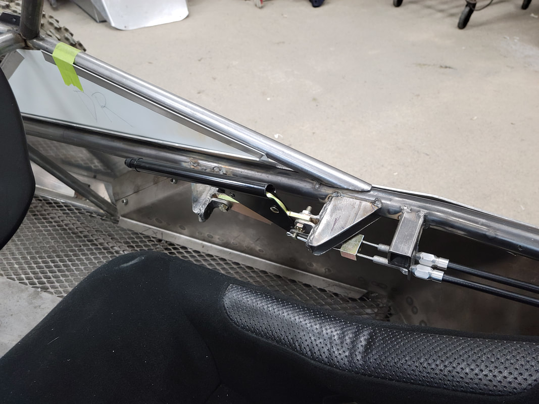
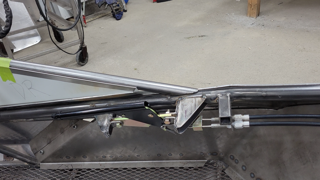
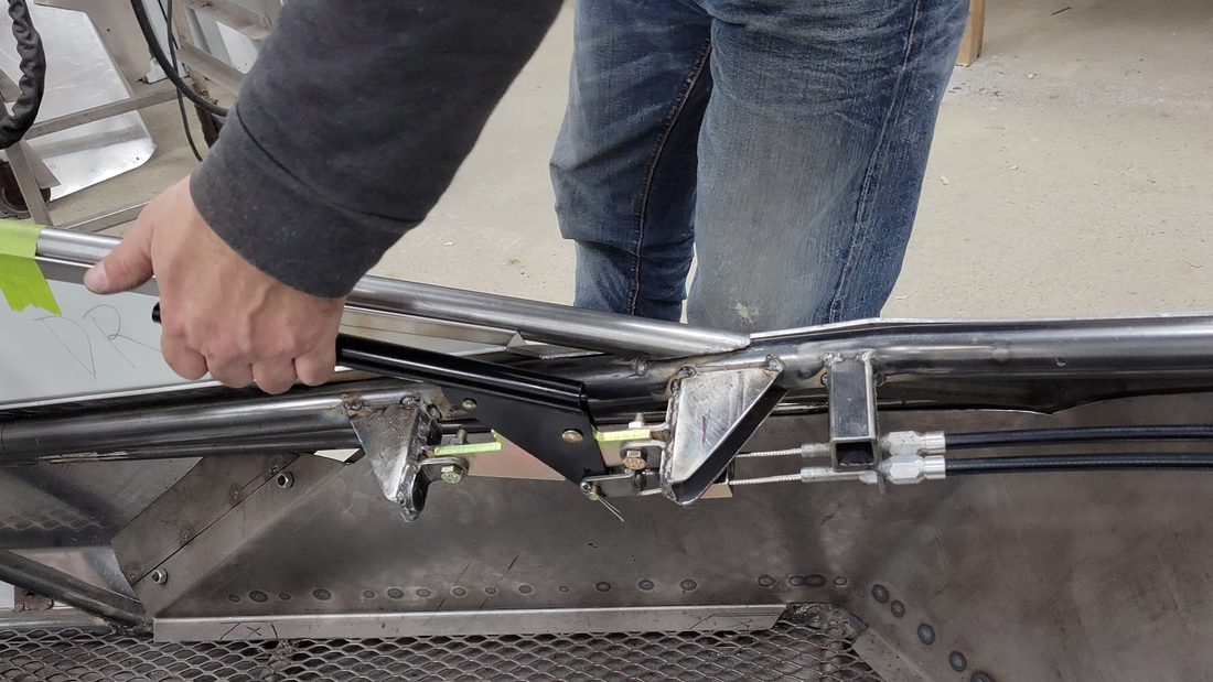
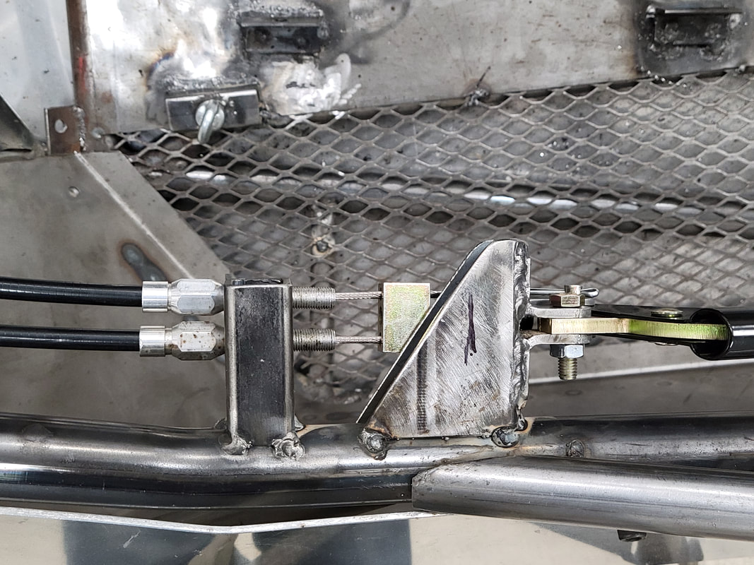
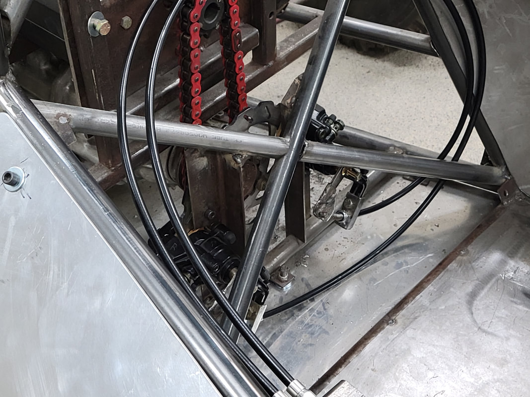
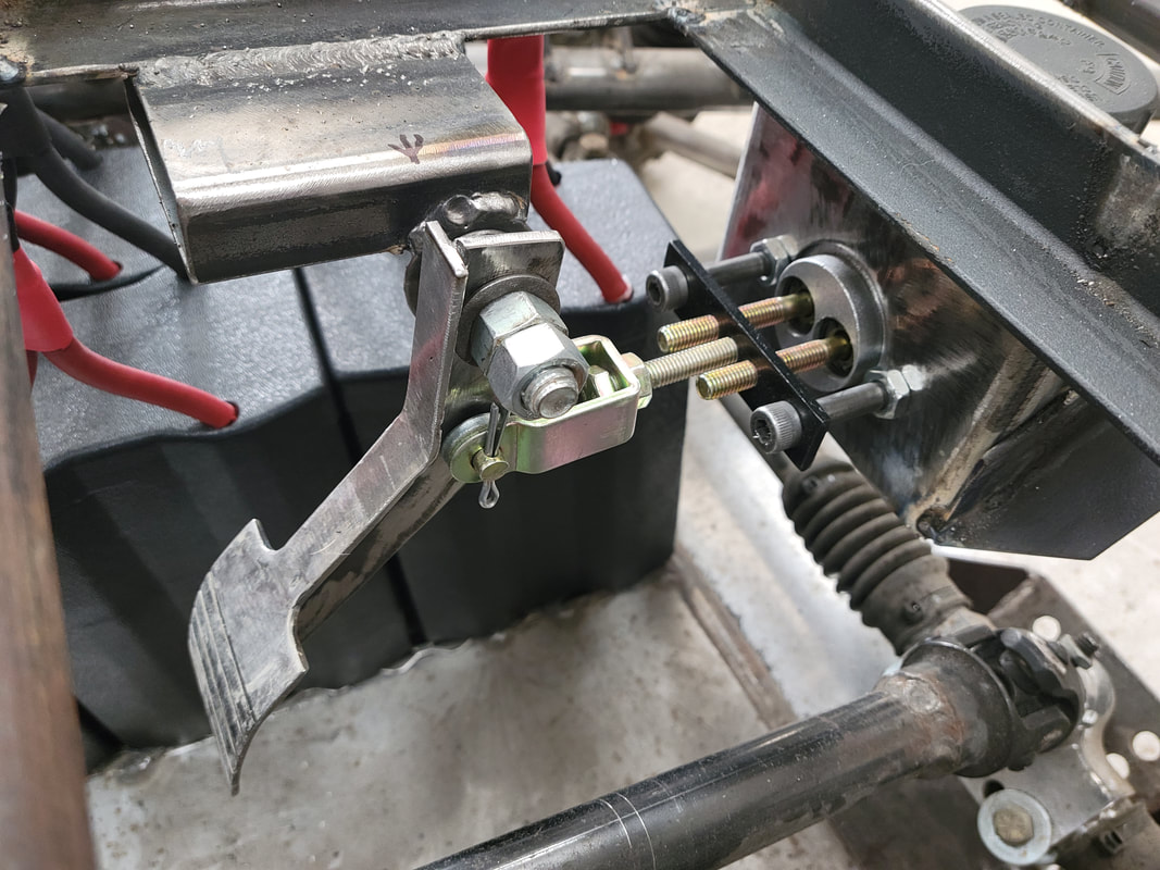
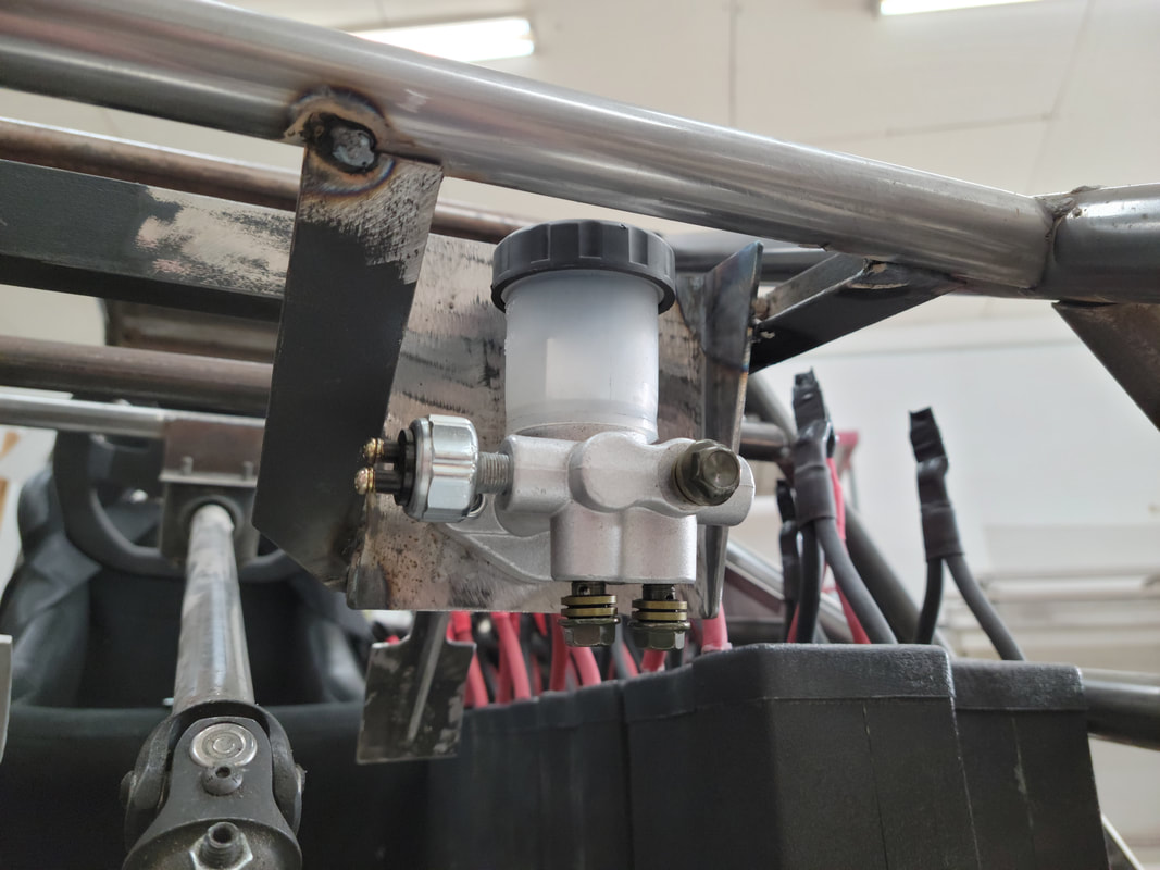
The hydraulic brakes will be controlled by a universal master cylinder made for atv's and buggies, which also comes with a switch installed for operating brake lights. It doesn't come with a brake pedal, so I made one from steel plate to match the electric throttle pedal.
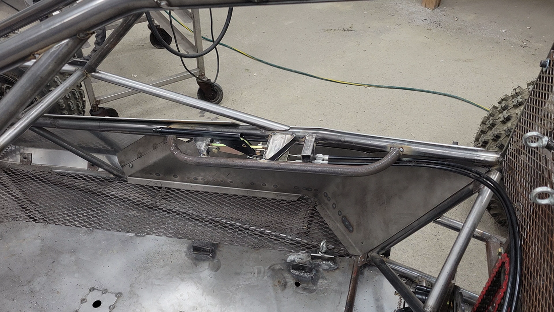
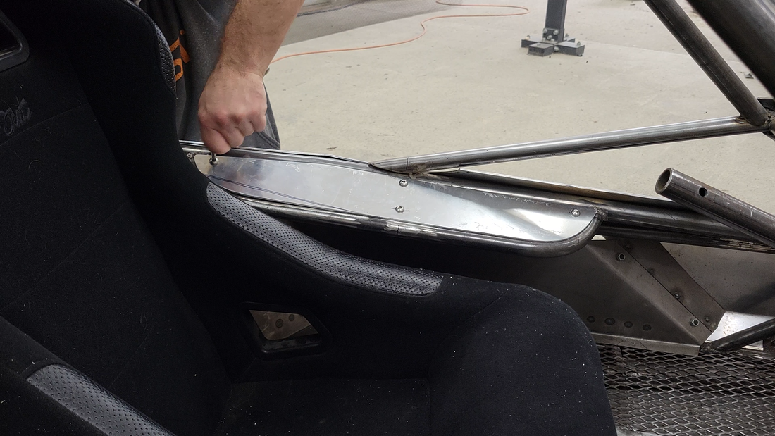
I also added some armrests, more for protection than resting. I needed a way to cover the mounting brackets for the handbrake, so I bent a couple pieces of 1" HREW steel tubing with a 4" radius on each end, welded them in place and covered them with 1/8" thick aluminum plate.
I also added some armrests, more for protection than resting. I needed a way to cover the mounting brackets for the handbrake, so I bent a couple pieces of 1" HREW steel tubing with a 4" radius on each end, welded them in place and covered them with 1/8" thick aluminum plate.
In this video I take a break from eating metal and abrasive dust in the workshop and make the battery modules for the electric crosskart project.
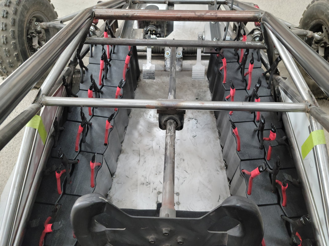
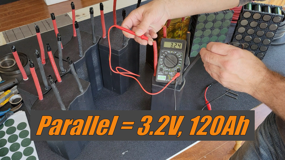
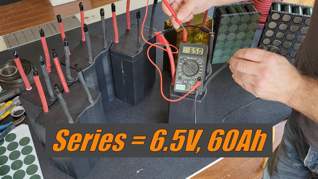
If you've been following the build from the beginning, you probably know that the original plan was to build the battery into the chassis' floor, like a typical EV. But I wanted a lower center of gravity and easier access to the battery for servicing, so I decided to split the battery into two packs that will be positioned on either side of the seat so that I can sit as low as possible without compromising ground clearance. The packs will each contain sixteen 3.2V, 120Ah LiFePo4 modules wired in series to produce 12.2 kWh at 102V nominal.
If you've been following the build from the beginning, you probably know that the original plan was to build the battery into the chassis' floor, like a typical EV. But I wanted a lower center of gravity and easier access to the battery for servicing, so I decided to split the battery into two packs that will be positioned on either side of the seat so that I can sit as low as possible without compromising ground clearance. The packs will each contain sixteen 3.2V, 120Ah LiFePo4 modules wired in series to produce 12.2 kWh at 102V nominal.
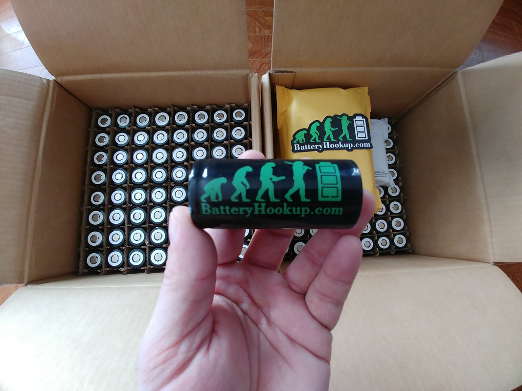
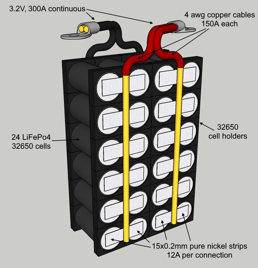
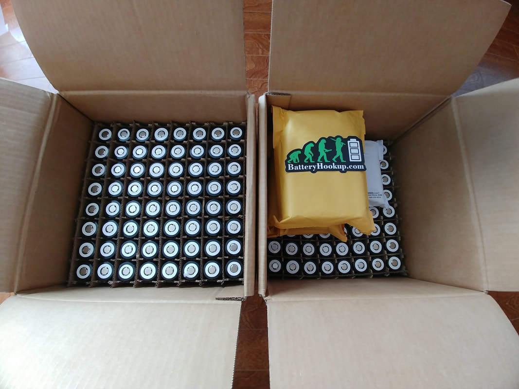
The modules are made up of twenty four 3.2V, 5000mAh 32650 LiFePo4 cells, all connected in parallel. The cells that I used were purchased from batteryhookup.com. I chose LFP (lithium iron phosphate) cells because next to LTO (lithium titanate oxide) they are the most stable lithium cells available, in that they won't explode and catch fire if there's damage or a short. The fact that batteryhookup.com is a domestic, family owned company with the best price online is another good reason why I chose these particular cells. They each have a continuous discharge current rating of 15A (3C, ie: 3 * amp hour capacity) and 50A peak (10C for approx. 10 seconds), and a continuous charge current rating of 5A (1C).
24 cells connected in parallel create a 3.2V module with 24 * 5Ah = 120Ah of capacity, 24 * 15A = 360A cont., 1200A peak discharge and 24 * 5 = 120A charge current capability.
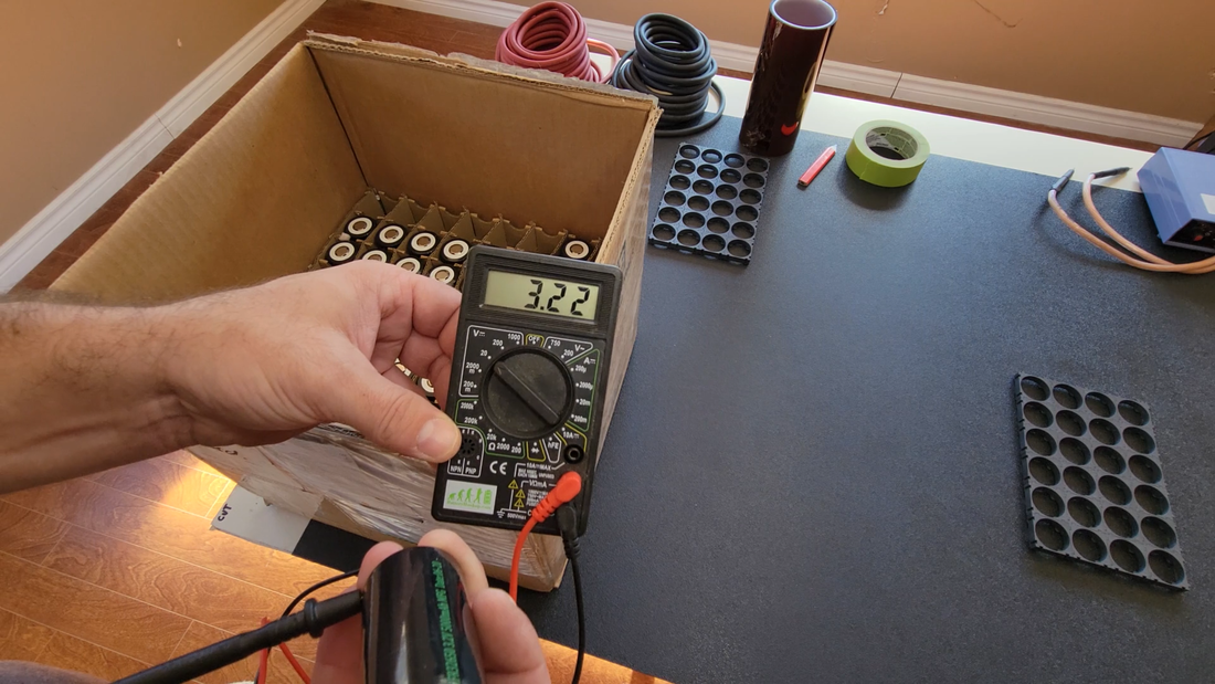
Before doing anything, I covered my work table with a sheet of ABS plastic to help prevent against accidental shorts while building the modules, and kept a pair of rubber gloves close by to wear when necessary. I then checked that the voltage of the cells were within 0.05V of each other. When cells of different voltages are connected in parallel, current will flow from the higher charged cell to the lower charged cell to equalize them, essentially turning them into one large cell. If the difference between any two cells is greater than 0.05V, then the rush of current after connecting them could be too great and cause damage to the cells or worse. 3.2V is nominal for LFP (lithium iron phosphate cells, or LiFePo4), so I used that as a benchmark and any cell that was between 3.2 and 3.25V. Cells that measured <3.2V were set aside and charged later to match.
Before doing anything, I covered my work table with a sheet of ABS plastic to help prevent against accidental shorts while building the modules, and kept a pair of rubber gloves close by to wear when necessary. I then checked that the voltage of the cells were within 0.05V of each other. When cells of different voltages are connected in parallel, current will flow from the higher charged cell to the lower charged cell to equalize them, essentially turning them into one large cell. If the difference between any two cells is greater than 0.05V, then the rush of current after connecting them could be too great and cause damage to the cells or worse. 3.2V is nominal for LFP (lithium iron phosphate cells, or LiFePo4), so I used that as a benchmark and any cell that was between 3.2 and 3.25V. Cells that measured <3.2V were set aside and charged later to match.
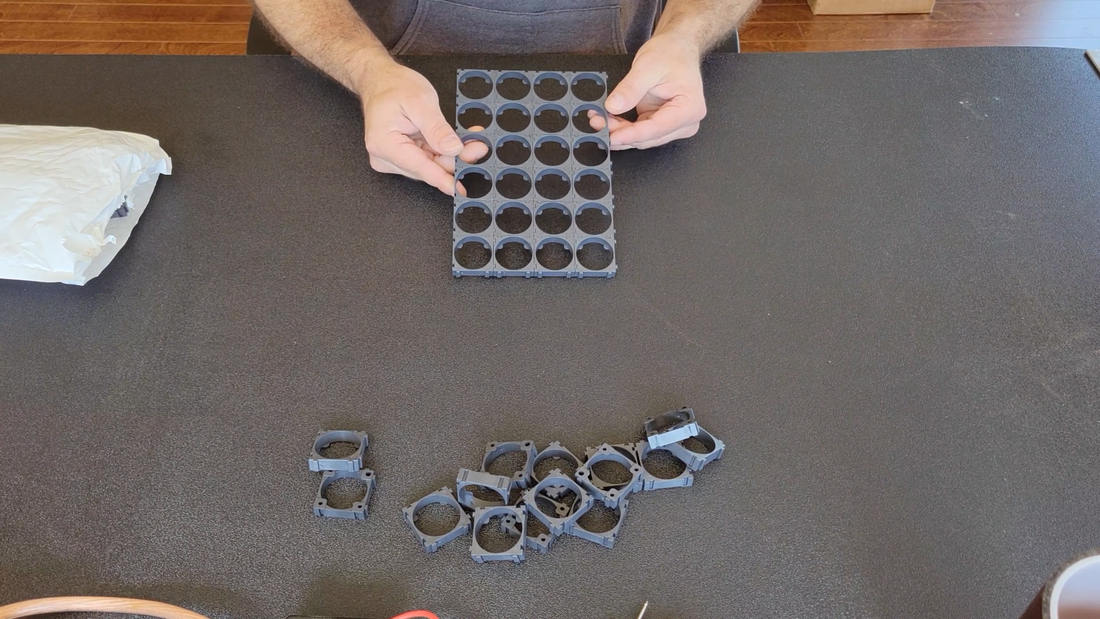
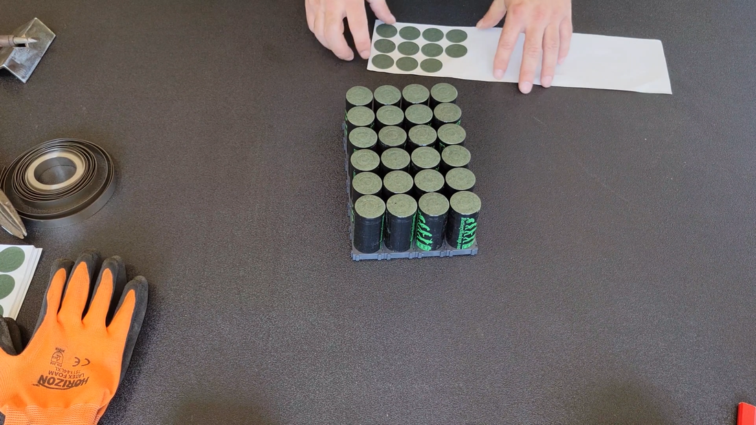
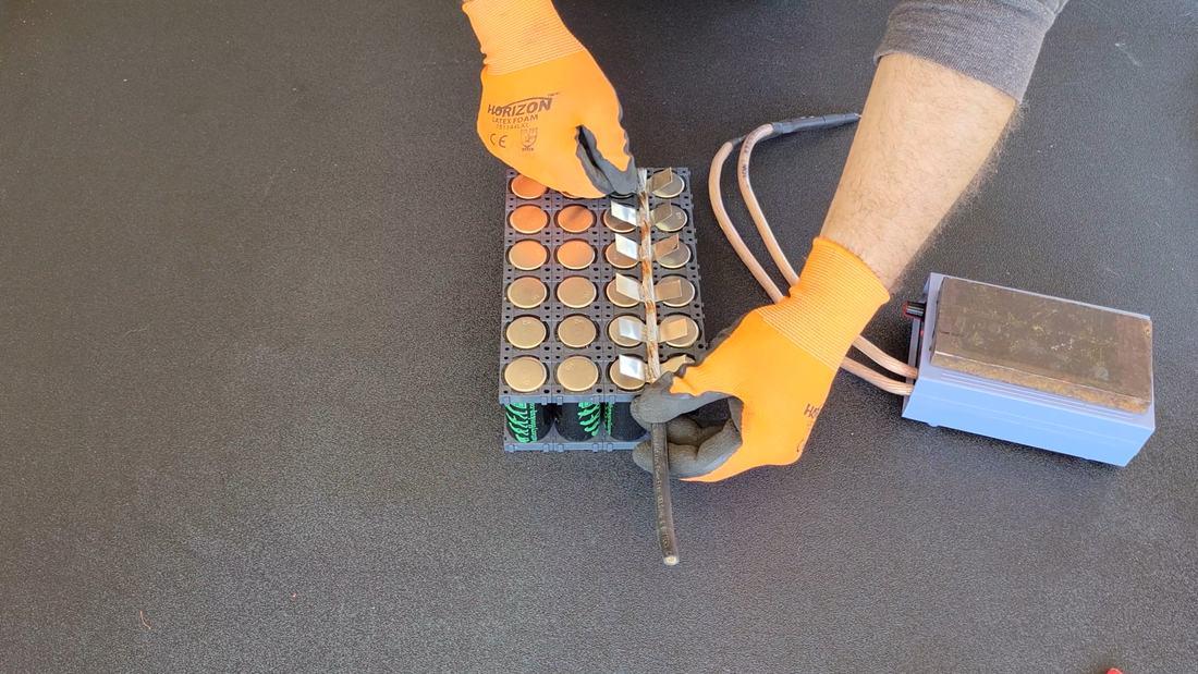
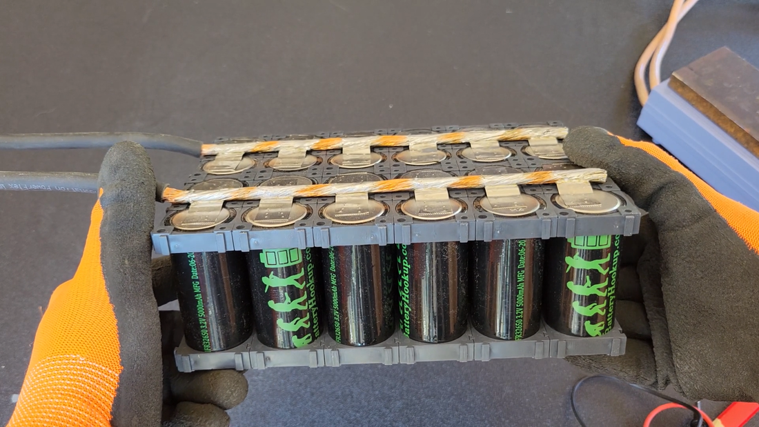
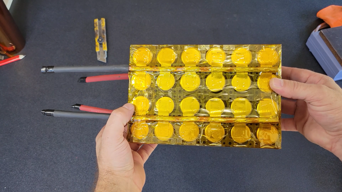
I used single 32650 cell holders from batteryhookup.com to assemble the cells into a 4x6 module configuration to suit the space constraints in the crosskart cabin. I had considered staggering the cells with hexagonal holders to fit them tighter together, but I couldn't find any to fit 32650's and ultimately I decided that the square holders will allow the cells to dissipate heat easier anyway.
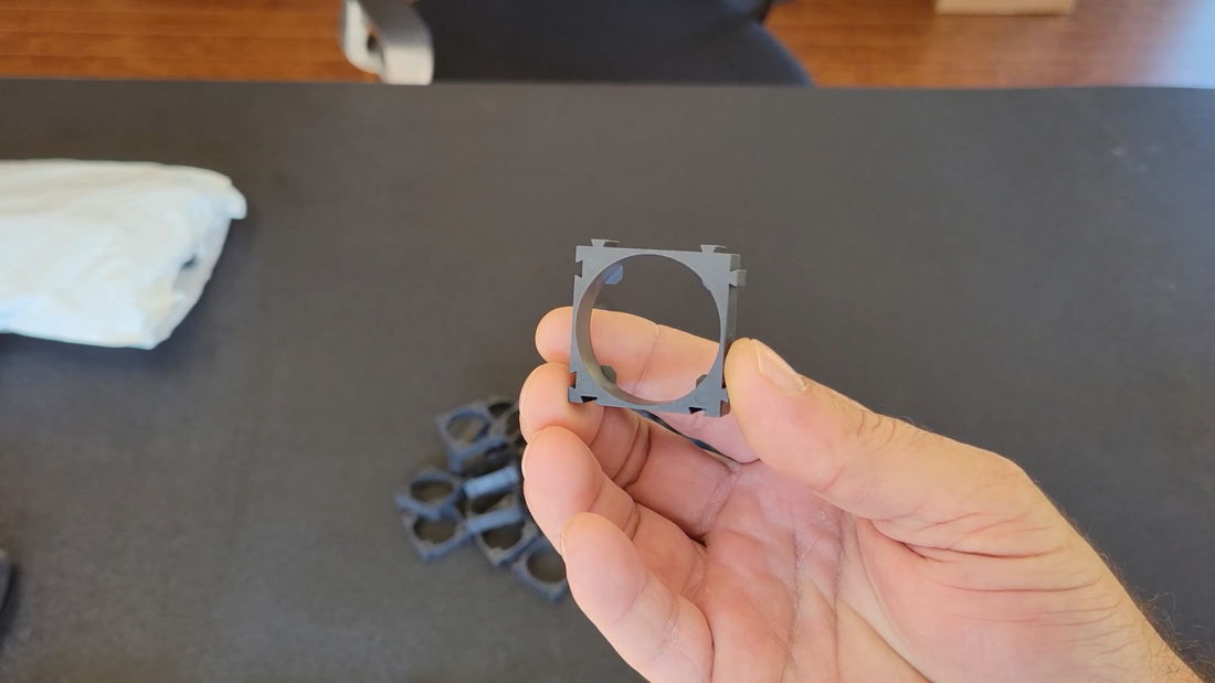
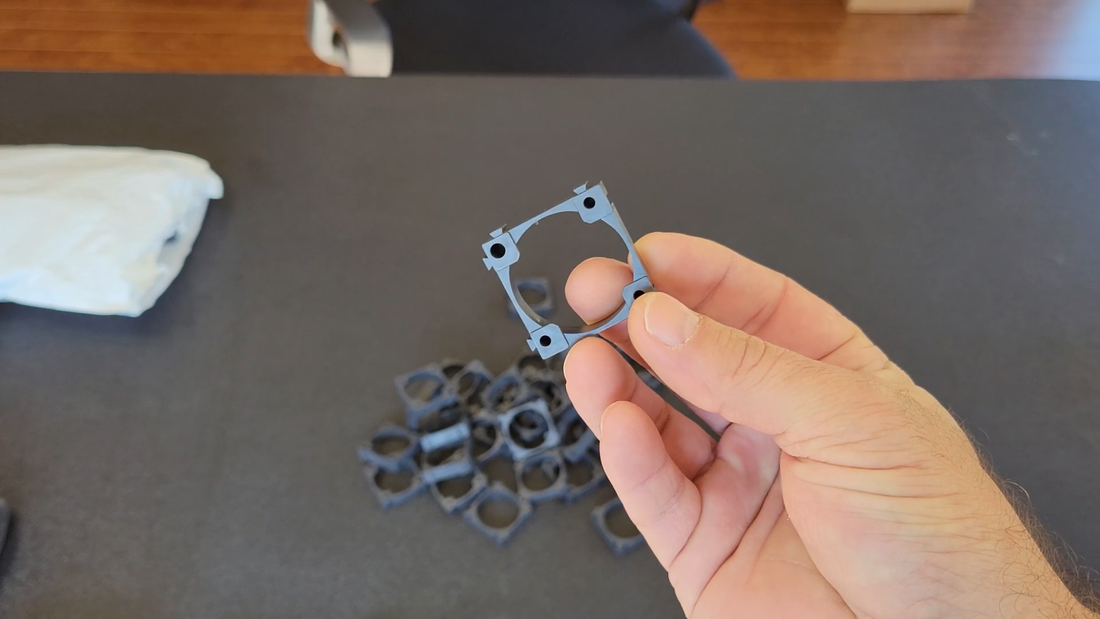
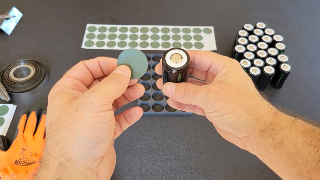
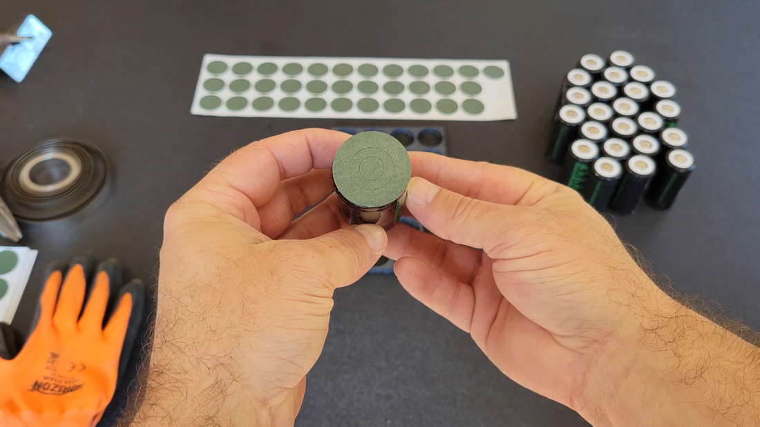
Batteryhookup.com also supplies insulation rings for their cells (sold separately). These have adhesive backings and are meant to cover the positive terminals on the cells to help prevent shorts while you're building your battery. The center of the rings are perforated so a small portion can be removed for making connections when needed. They also provide better insulation between the positive connections and the cell casing to prevent shorts after assembly.
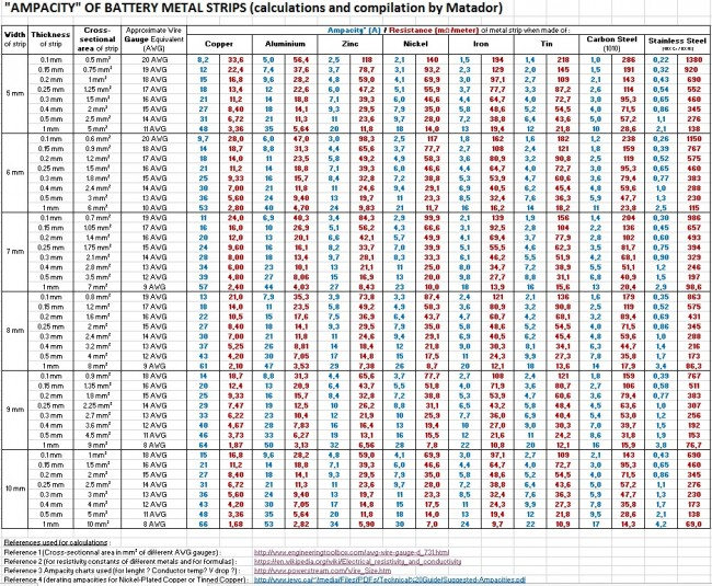
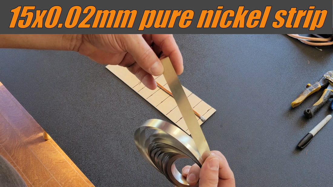
The cells were connected using 15x0.2mm (3 mm^2) pure nickel strips and 4 awg (21 mm^2) flexible copper cable from Windy Nation. As shown in the charts and image below, the cables and strips are sized large enough (cross sectional area in mm^2) to safely handle the current that the motor is going to pull from the battery without overheating, +10-20%.
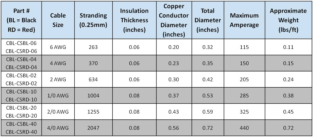
The ME1616 motor is rated for 250A continuous and 600A peak. One layer of 3 mm^2 pure nickel strip can handle ~12A of current. With current draw being shared by every cell in a parallel (P) group, the nickel strips will only need to handle 250A / 24 cells = 10.4A continuously each. The chart below shows the ampacity of different sizes and types of conductors for connecting battery cells. Note that it only lists strips up to 10mm wide, but it's the cross sectional area of the conductor that determines its ampacity. For example, the 15x0.2mm pure nickel strips that I used have the same ampacity as 10x0.3mm pure nickel because the cross sectional area of both is 3 mm^2.
I should also point out that not all nickel strips that are sold are pure nickel, either. Some are copper or steel with nickel plating. The nickel plated copper strips will have a higher ampacity because copper is more conductive than nickel so thinner strips can be used, but because of the higher conductivity they'll be harder to spot weld to the cells without an expensive, high power welder that can generate enough heat to make a secure weld. Nickel plated steel has a lower ampacity than pure nickel and are easier to spot weld, but thicker strips are needed to compensate and the steel has a potential to rust. Aluminum is a good conductor but isn't common in battery packs, at least not home built packs, because soldering and conventional spot welding methods don't work for aluminum. Tesla has aluminum bus plates in their EV modules, for ex, but use ultrasonic welding (vibrations) for bonding fuse wire to them instead of electrical resistance welding.
I should also point out that not all nickel strips that are sold are pure nickel, either. Some are copper or steel with nickel plating. The nickel plated copper strips will have a higher ampacity because copper is more conductive than nickel so thinner strips can be used, but because of the higher conductivity they'll be harder to spot weld to the cells without an expensive, high power welder that can generate enough heat to make a secure weld. Nickel plated steel has a lower ampacity than pure nickel and are easier to spot weld, but thicker strips are needed to compensate and the steel has a potential to rust. Aluminum is a good conductor but isn't common in battery packs, at least not home built packs, because soldering and conventional spot welding methods don't work for aluminum. Tesla has aluminum bus plates in their EV modules, for ex, but use ultrasonic welding (vibrations) for bonding fuse wire to them instead of electrical resistance welding.
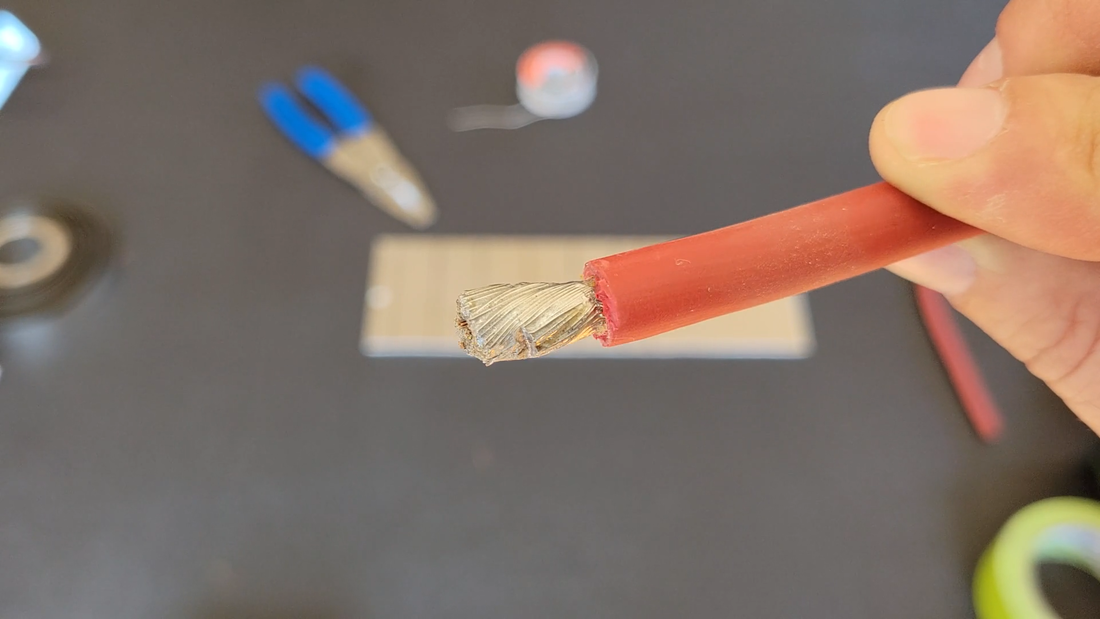
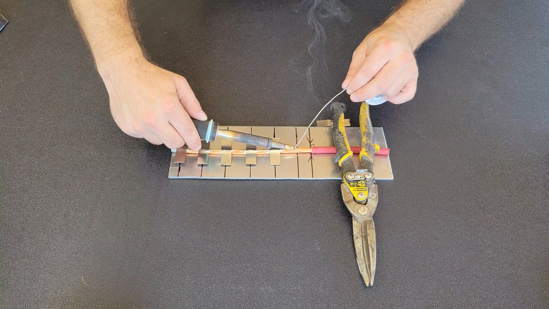
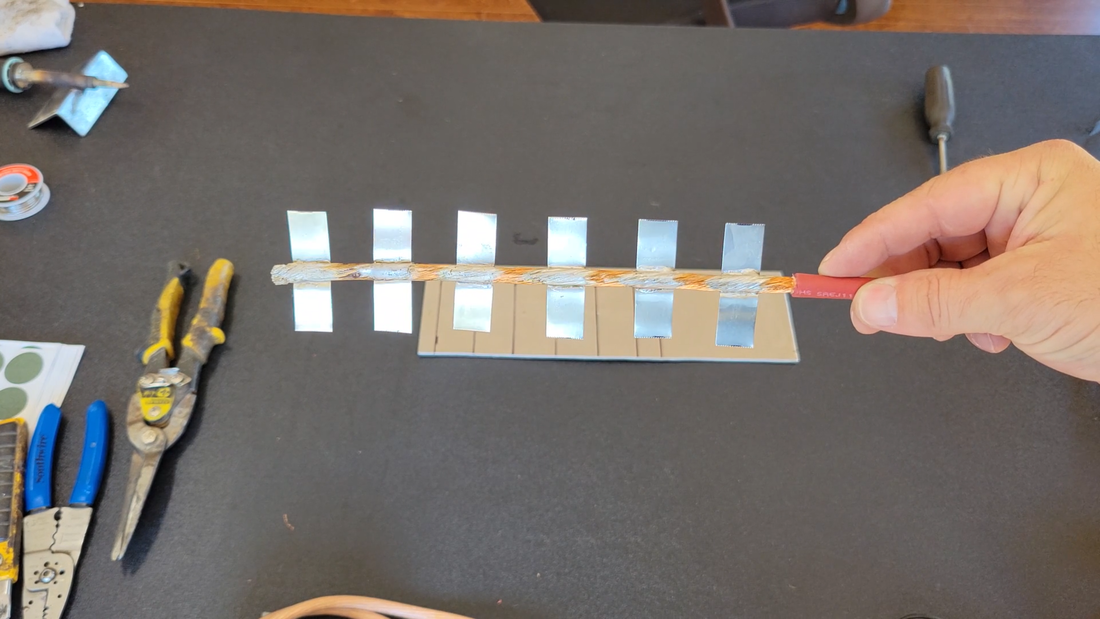
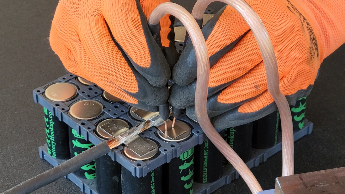
After the cells were assembled in the holders and the insulator rings were installed, I cut the 4 awg cables to length then stripped a short section of insulation off one end and soldered the wire. This kept the wire from unravelling after I stripped the rest of the insulation from it.
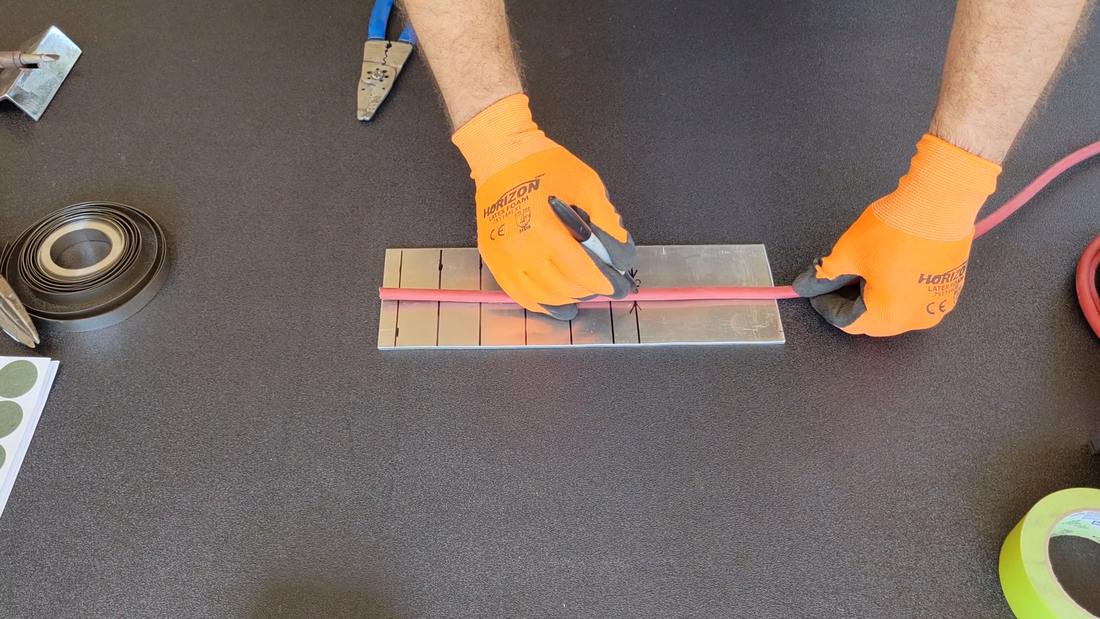
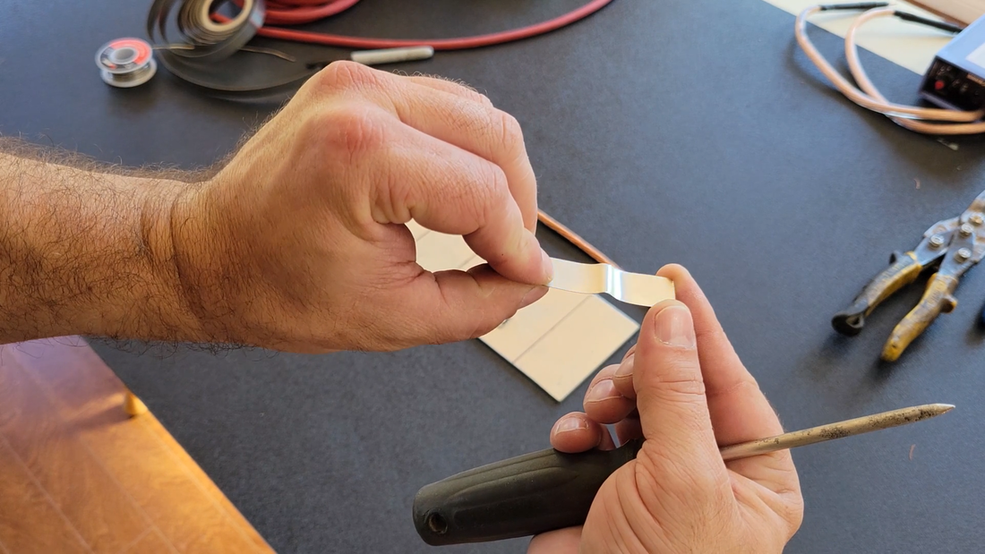
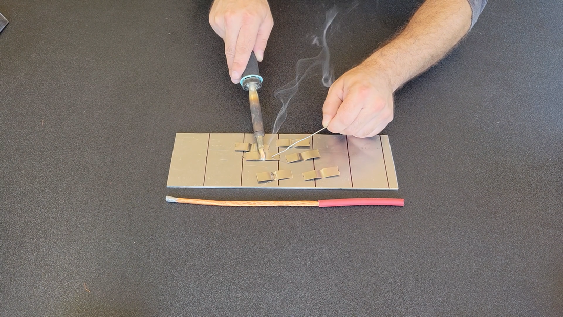
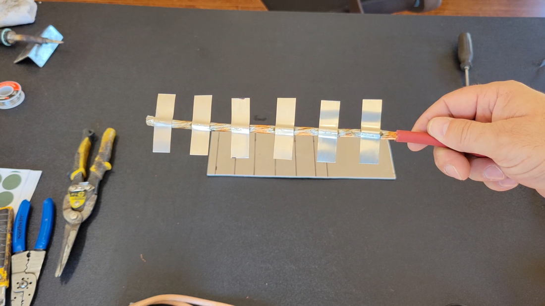
I then cut 6 pieces of nickel strip at 2" long, and bent them around a scratch awl to form a profile that will wrap around a portion of the copper cable. Then I tinned the strips and soldered them to the cable using a Weller W100PG heavy duty soldering iron, 40/60 rosin core solder (NOT acid core), and an aluminum template that I made to space the strips apart at the proper distance and location. The strips should be soldered to the cables BEFORE spot welding them to the cells because soldering to the cable requires a lot of heat that can transfer through the strips and damage the cells.
I then cut 6 pieces of nickel strip at 2" long, and bent them around a scratch awl to form a profile that will wrap around a portion of the copper cable. Then I tinned the strips and soldered them to the cable using a Weller W100PG heavy duty soldering iron, 40/60 rosin core solder (NOT acid core), and an aluminum template that I made to space the strips apart at the proper distance and location. The strips should be soldered to the cables BEFORE spot welding them to the cells because soldering to the cable requires a lot of heat that can transfer through the strips and damage the cells.
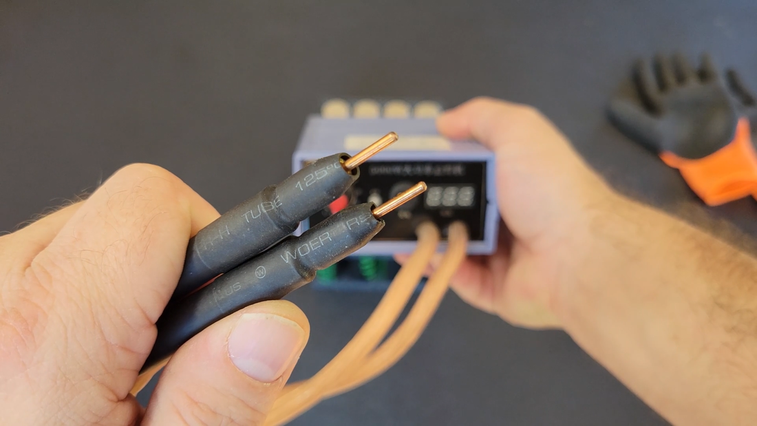
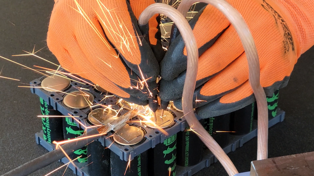
Once the strips were soldered to the cables, I cleaned off any remaining flux with rubbing alcohol, then welded the remaining ends of the strips to the cells negative terminals with a cheap 5000W spot welder, using 3-4 welds per connection. It did the job, the connections are plenty strong enough. But it's limited in the thickness of nickel strip that it can weld, being 0.25mm max, single layer. If you plan on building a big or a lot of batteries, I recommend getting yourself a K Weld. You'll need a powerful welder to make strong, reliable connections, otherwise vibrations from driving your EV later can work a weak weld loose and shut you down. Most of the sub $100 spot welders aren't up to the task.
Another thing to keep in mind is that the job of the welder is to hold the strip flat against the cell terminal, so avoid making unnecessary kinks in the strips where they're to be welded or short spaced center welds that could allow lifting of a portion of the strip and affect the connection and/or create a hot spot in the pack.
Another thing to keep in mind is that the job of the welder is to hold the strip flat against the cell terminal, so avoid making unnecessary kinks in the strips where they're to be welded or short spaced center welds that could allow lifting of a portion of the strip and affect the connection and/or create a hot spot in the pack.
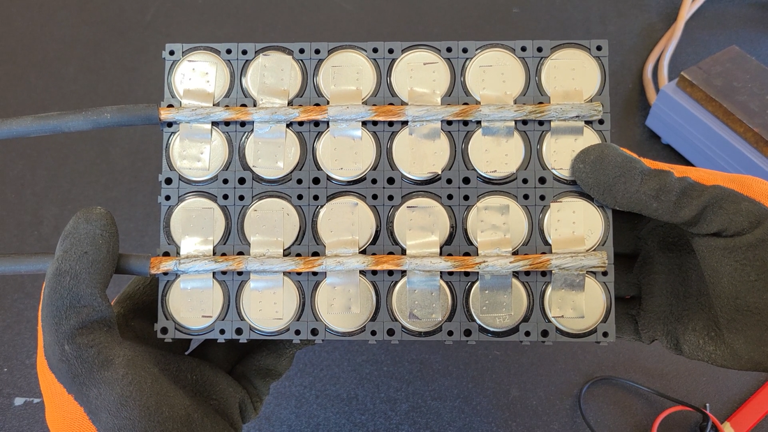
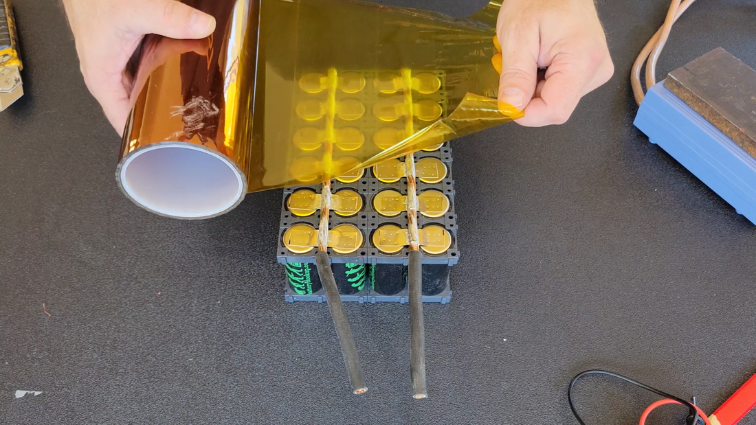
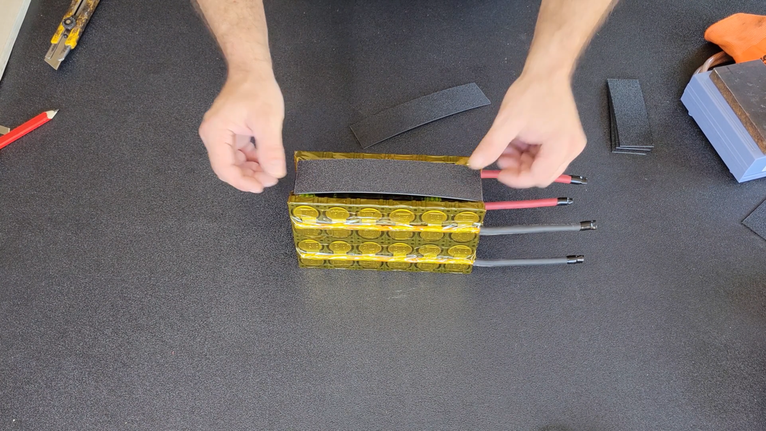
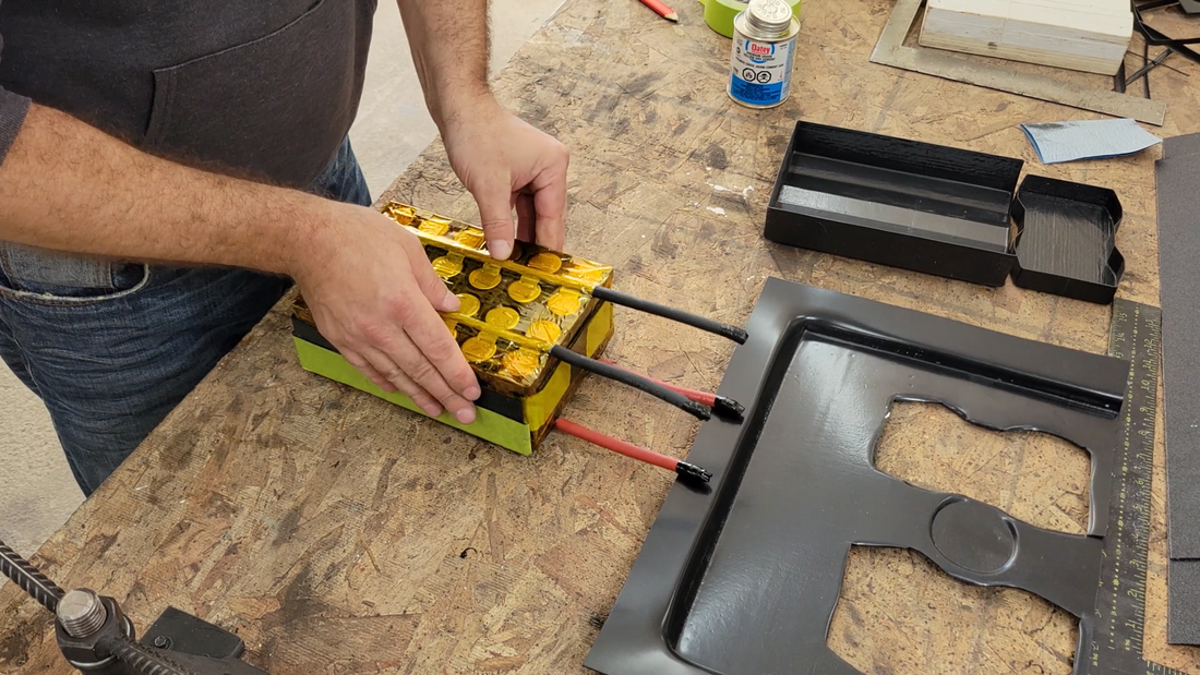
After the negative cables were connected, I covered that side of the module with Kapton tape to seal and protect it, then removed the center tabs from the insulator rings on the positive terminals and spot welded the positive cables in place.
I also cut some strips of 1/16" thick ABS plastic and taped them to the sides, top and bottom of the modules to add more protection to the cells.
I also cut some strips of 1/16" thick ABS plastic and taped them to the sides, top and bottom of the modules to add more protection to the cells.
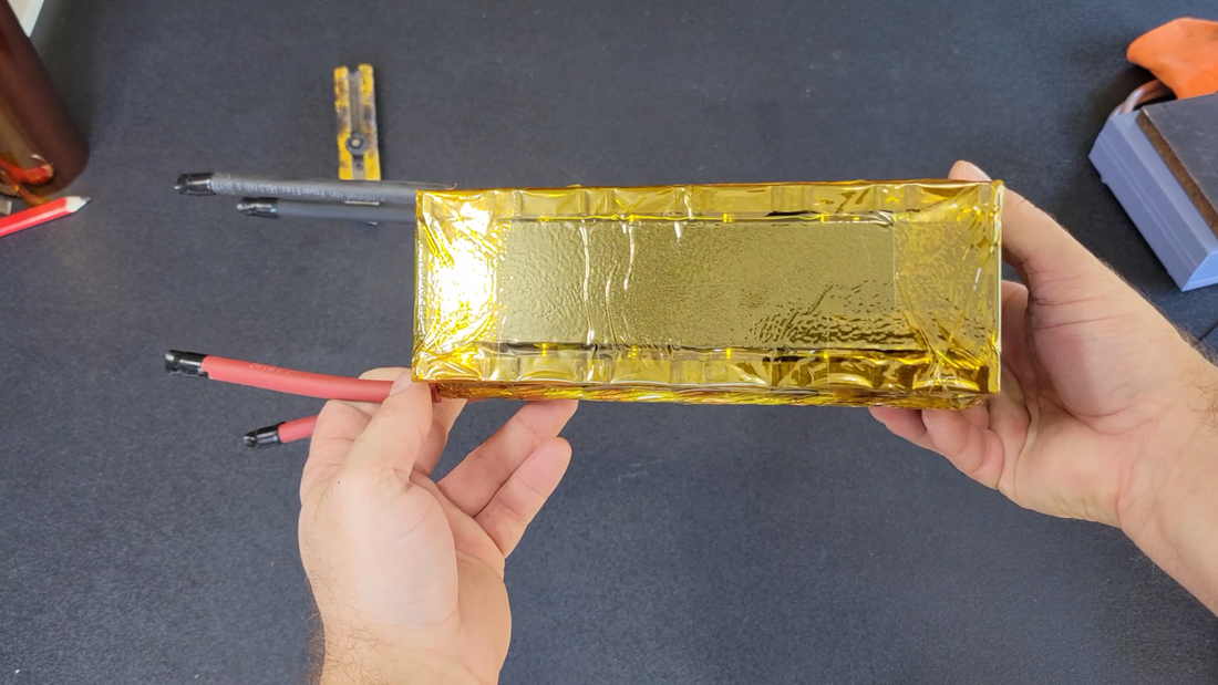
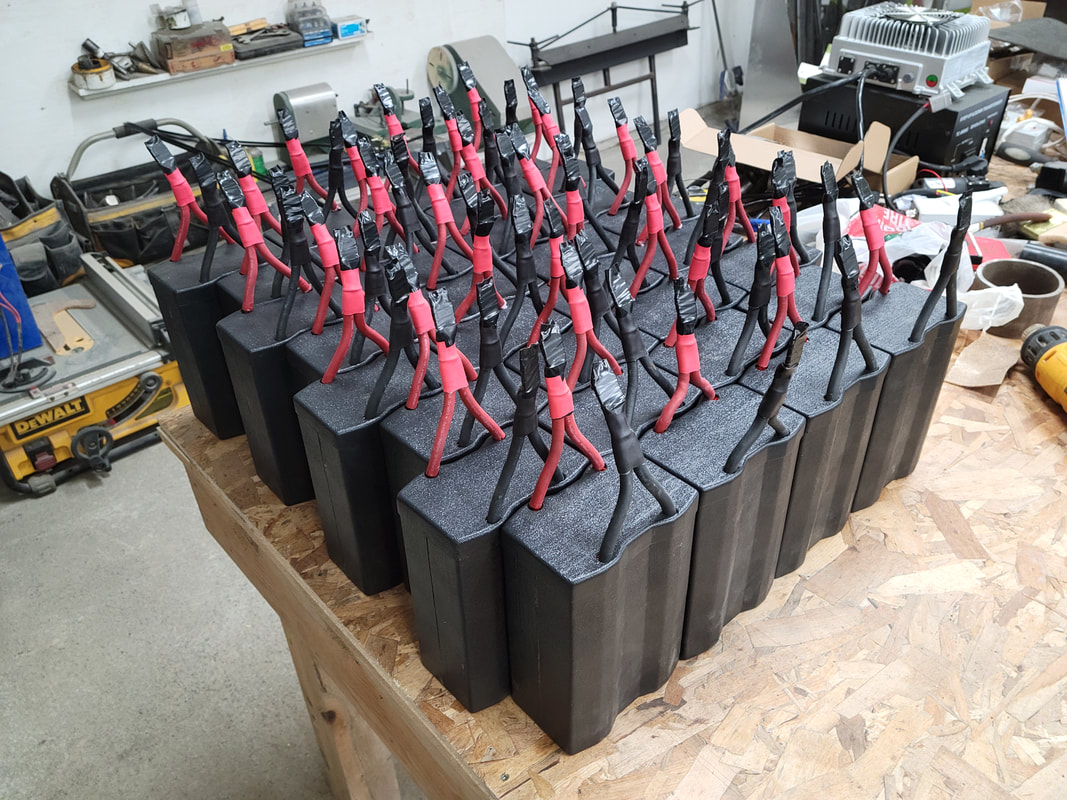
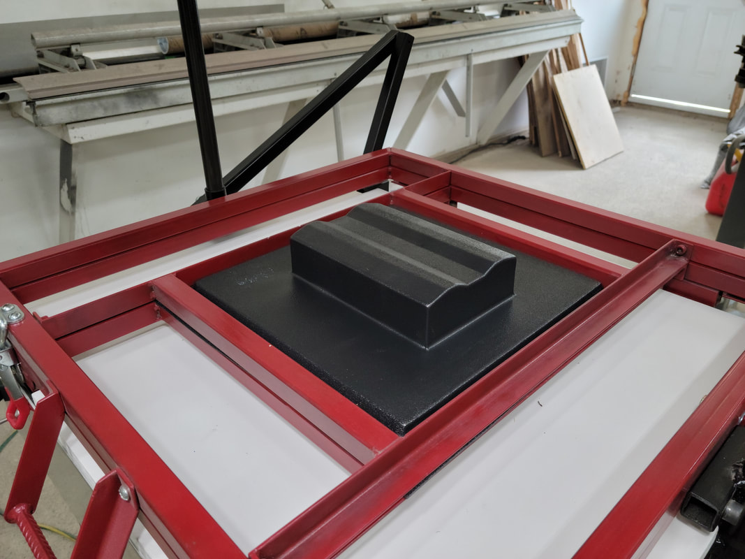
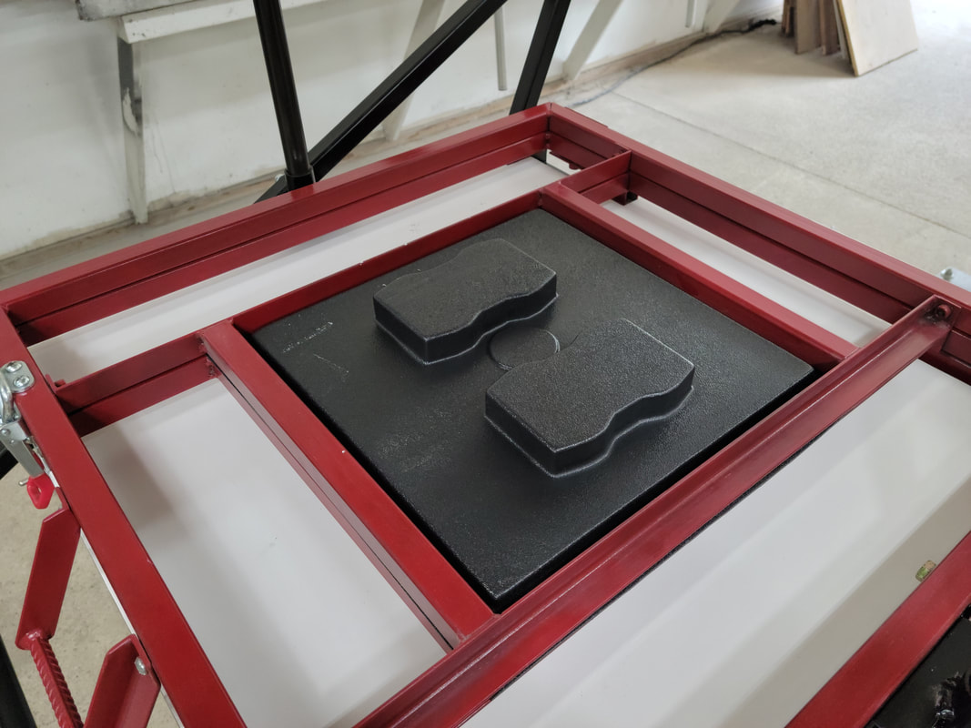
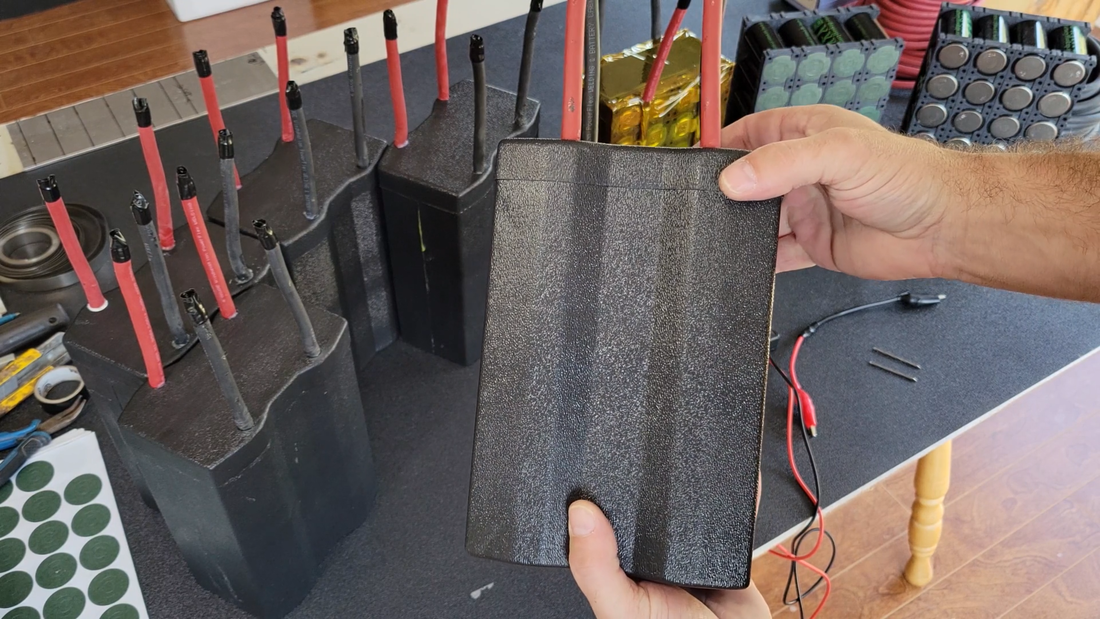
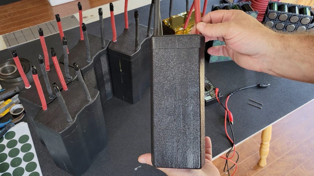
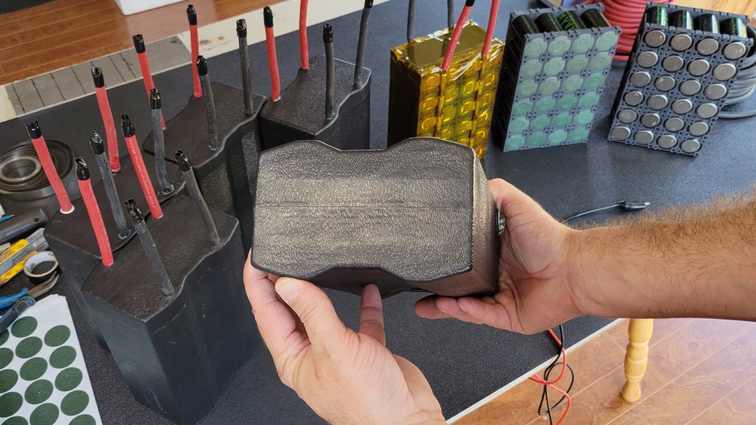
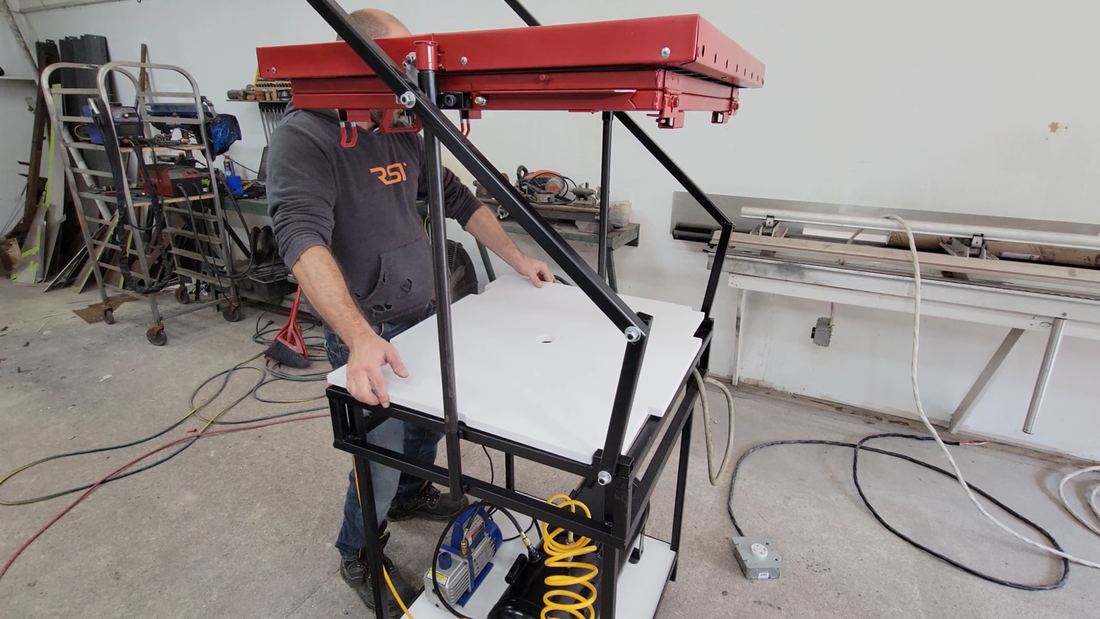
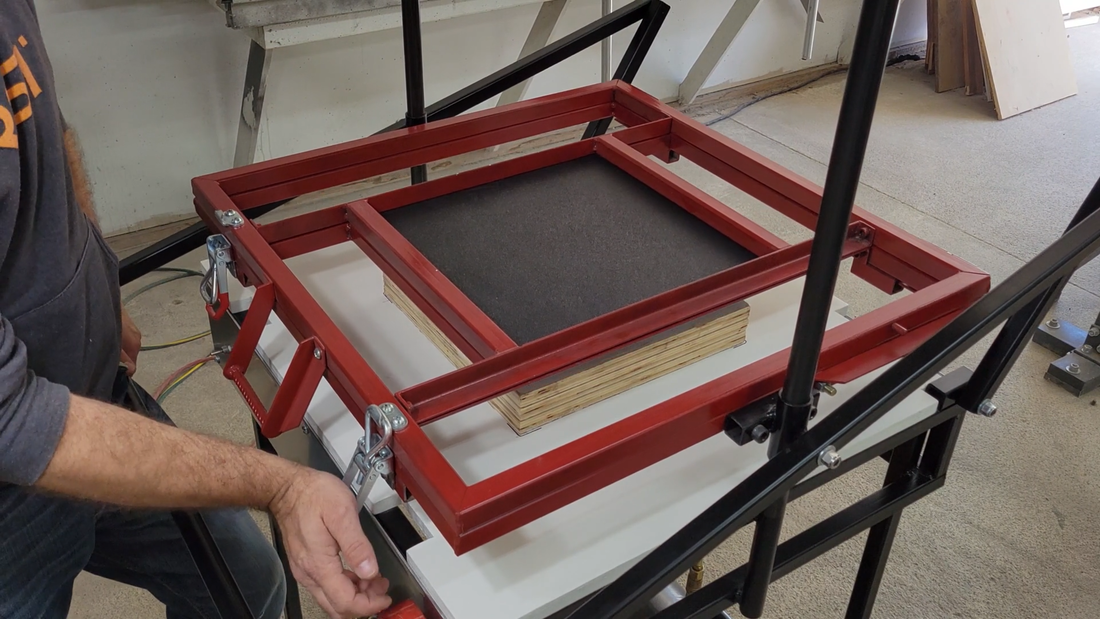
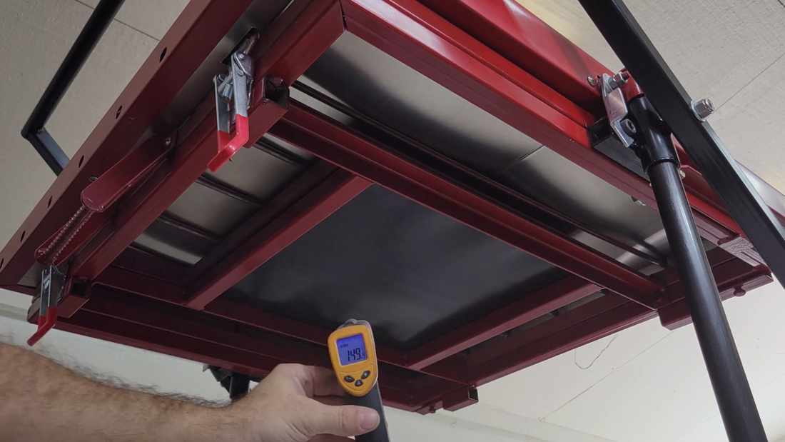
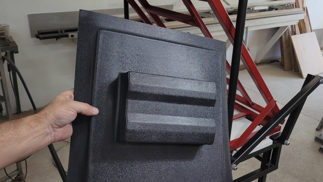
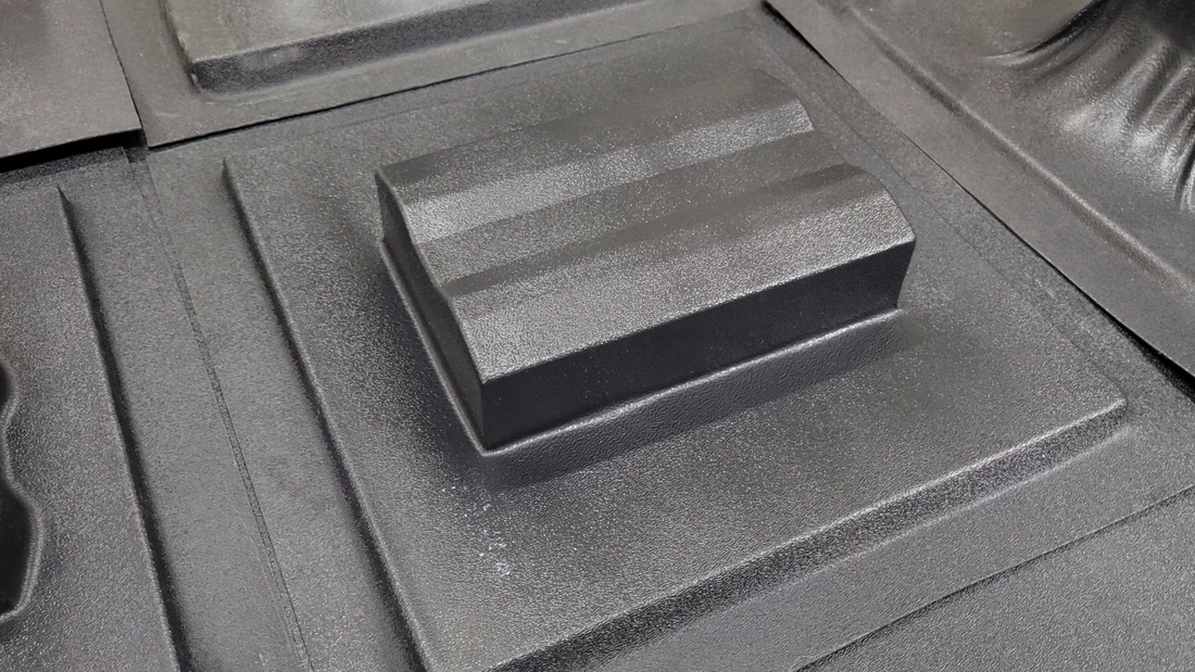
I then used my new vacuum former to make ABS cases for the modules. I built the former last month specifically for this job, but it's going to be a handy piece of equipment to have in the workshop that I can use for loads of other projects, so the time spent building it was well worth it. I recommend checking out the build article to learn how it works and how to build it.
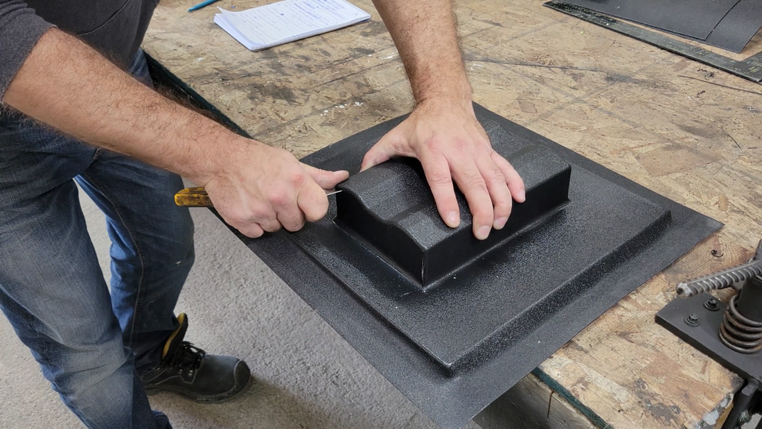
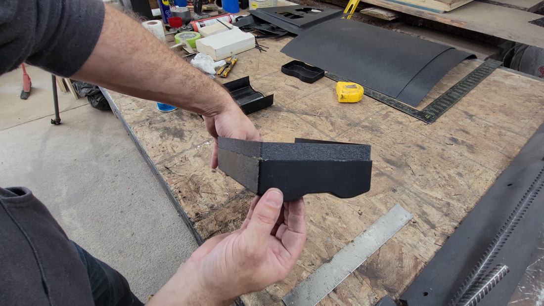
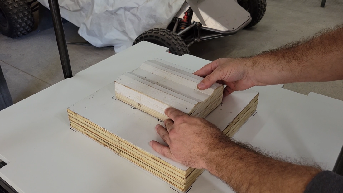
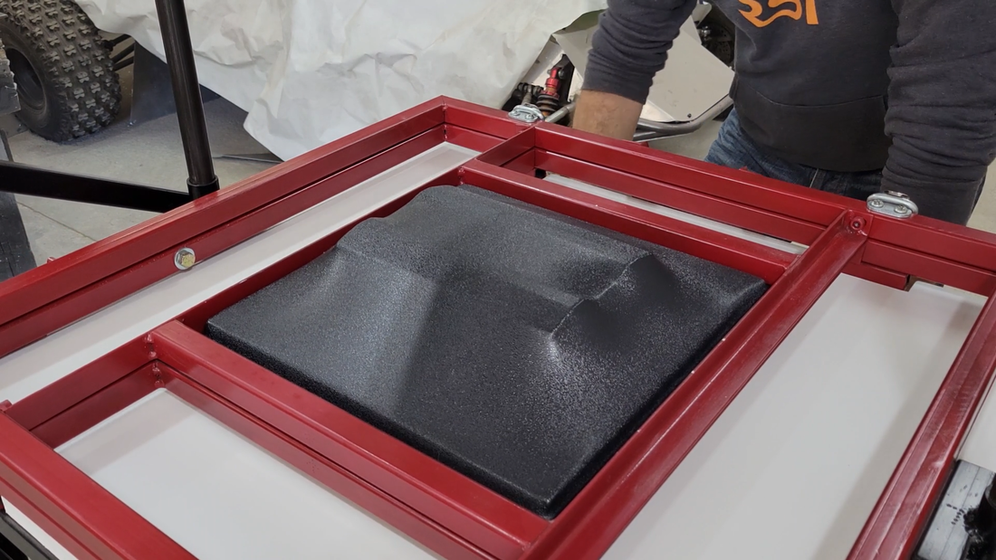
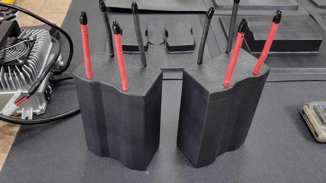
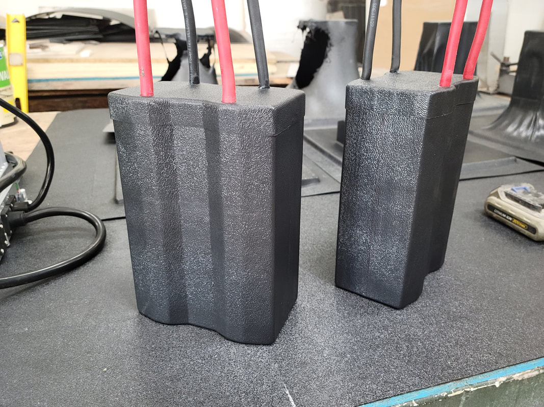
I tried to form the cases in just two pieces, ie: top and bottom, but the draw depth was too much for the sheet size and thickness, and the buck surfaces were too vertical. This caused the first few forming attempts to fail by stretching the ABS sheet too thin and tearing it and causing excess material to bunch up in the corners. I ultimately decided to form the cases in 3 pieces - one short cap for the top and two halves for the longer bottom section.
I tried to form the cases in just two pieces, ie: top and bottom, but the draw depth was too much for the sheet size and thickness, and the buck surfaces were too vertical. This caused the first few forming attempts to fail by stretching the ABS sheet too thin and tearing it and causing excess material to bunch up in the corners. I ultimately decided to form the cases in 3 pieces - one short cap for the top and two halves for the longer bottom section.
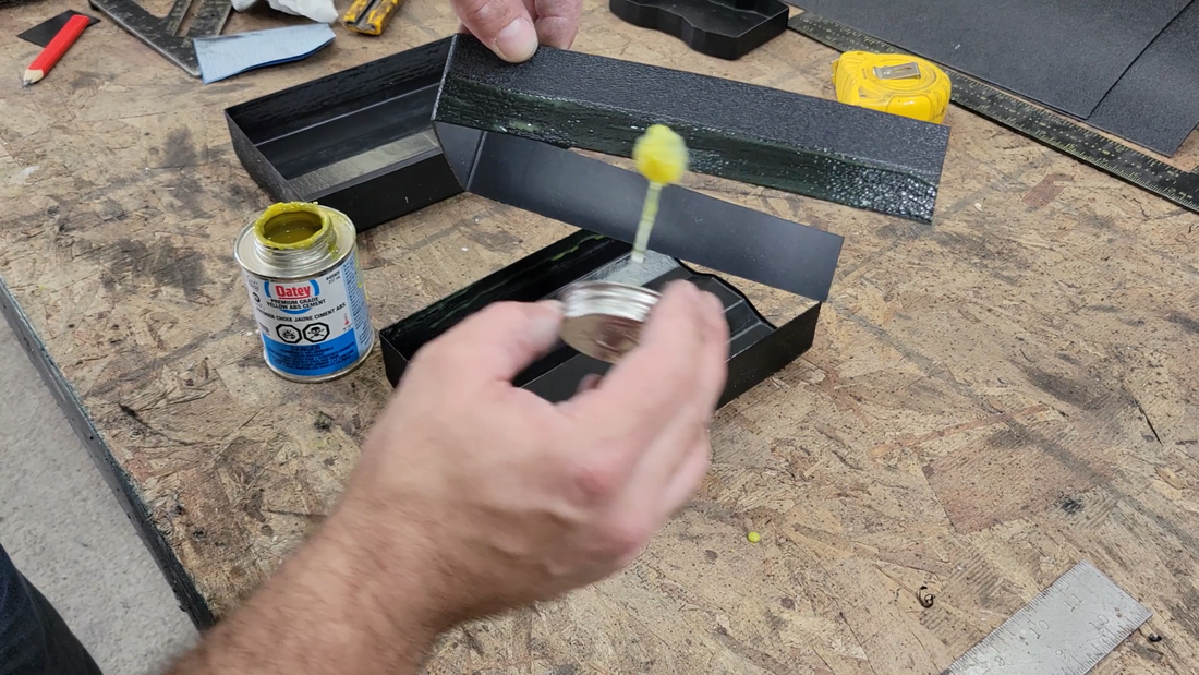
The cases were assembled using ABS backing strips and solvent cement. ABS solvent cement is more than just a glue; it reacts with the plastic to melt it to a point where the married surfaces are chemically welded together when the it cures. It's impossible to separate the joint without breaking the plastic if it's done right, and it's water tight. I also used silicone sealant under the cap where the cables exit, and installed the cap while the silicone was still wet.
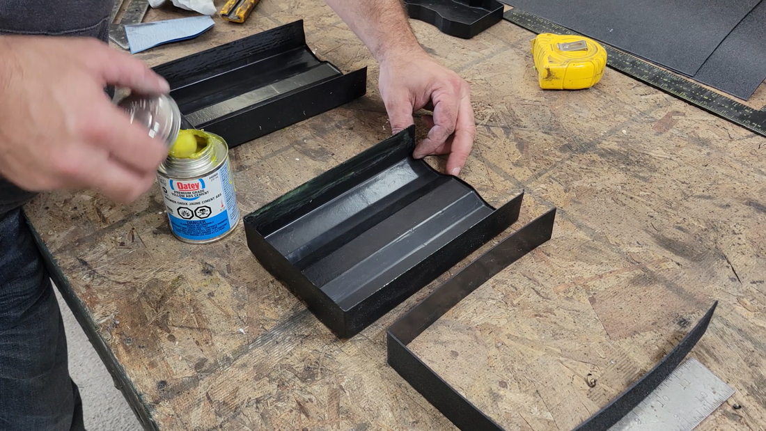
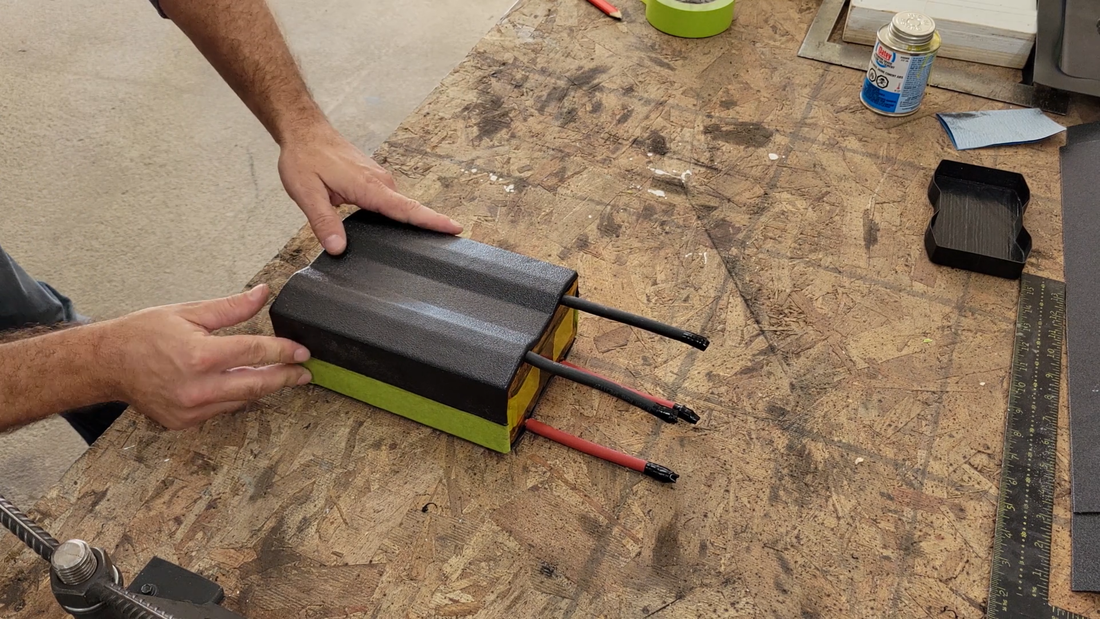
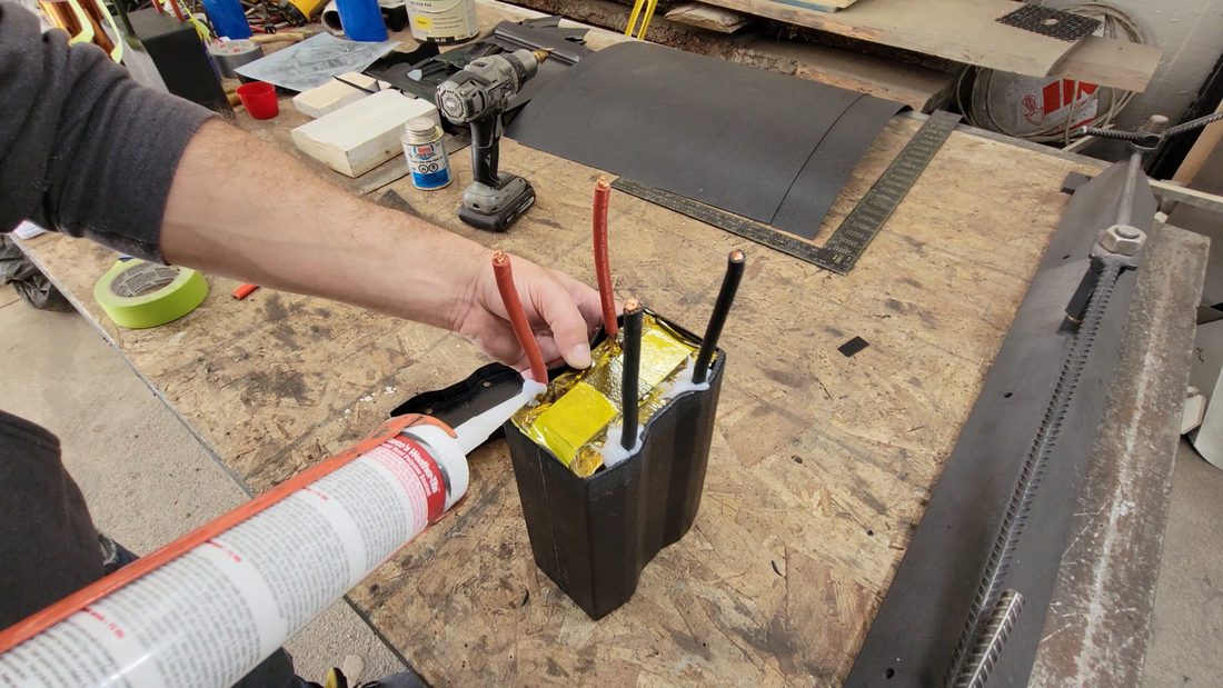
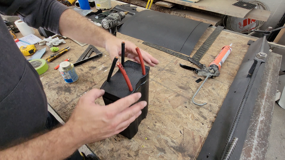
I wouldn't go so far as to say that these modules are waterproof and can be submerged completely in deep water, but they're sealed well enough to be partially submerged at least (up to the cable exit locations), and will keep dust and splashes of water away from the cells when I'm riding in the trail or hosing mud off the kart.
In this video I build a vacuum former. Vacuum forming is a version of thermoforming, where a plastic sheet is heated to just above its glass transition temperature (forming temperature) without melting, stretched over a single surface mold, and then pulled into the mold by a vacuum where it cools and maintains the desired shape. It's a simple, affordable method that both hobbyists and OEM's use to produce anything from plastic project cases and molds to automotive body panels, trims and construction equipment.
There was a time when I would have built something quick using a simple wooden box, heat gun and a shop vac, but the older I get the less I want to be constantly making quick throw-together jigs that only work for specific projects and then get tossed in a corner to collect dust for a decade. I want something more versatile and reliable, especially since the trigger for this build was needing to put the battery modules for the crosskart project in sealed cases to protect them from dust and water when I'm driving in the trails. It's next to impossible to find premade project cases that are the right size, given the space constraints in the crosskart cabin. This former allowed me to make the cases easily myself, and they look like something that I would have paid a manufacturer to produce for me. Read below for the details on how I did it and what I learned in the process.
There was a time when I would have built something quick using a simple wooden box, heat gun and a shop vac, but the older I get the less I want to be constantly making quick throw-together jigs that only work for specific projects and then get tossed in a corner to collect dust for a decade. I want something more versatile and reliable, especially since the trigger for this build was needing to put the battery modules for the crosskart project in sealed cases to protect them from dust and water when I'm driving in the trails. It's next to impossible to find premade project cases that are the right size, given the space constraints in the crosskart cabin. This former allowed me to make the cases easily myself, and they look like something that I would have paid a manufacturer to produce for me. Read below for the details on how I did it and what I learned in the process.
 | 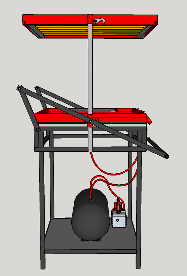 |
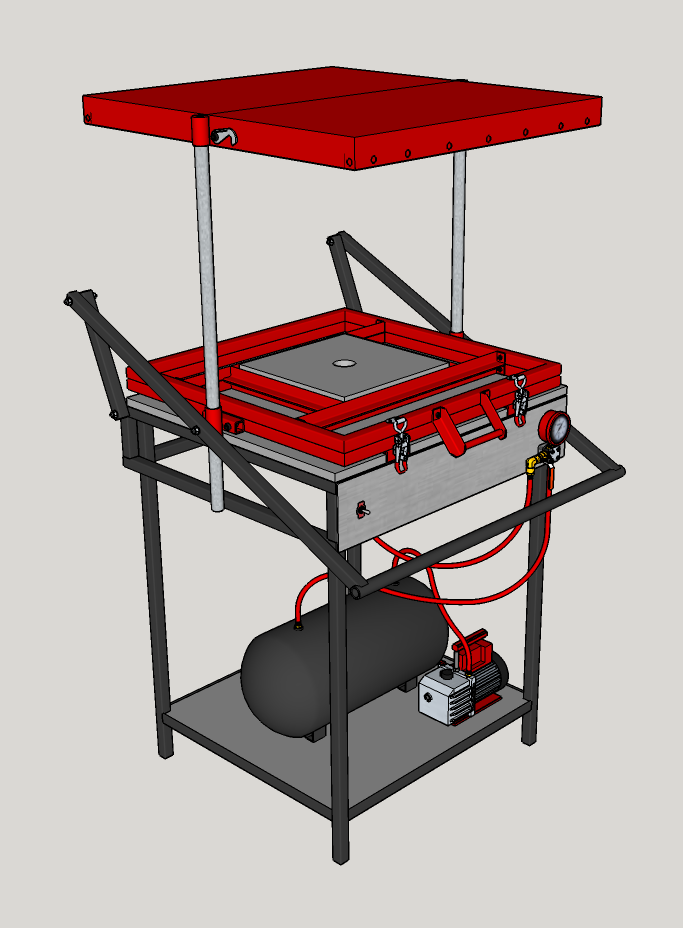
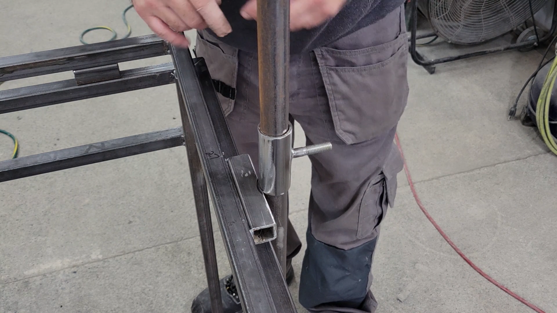
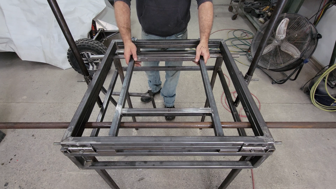
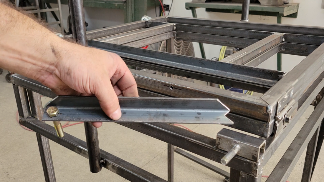
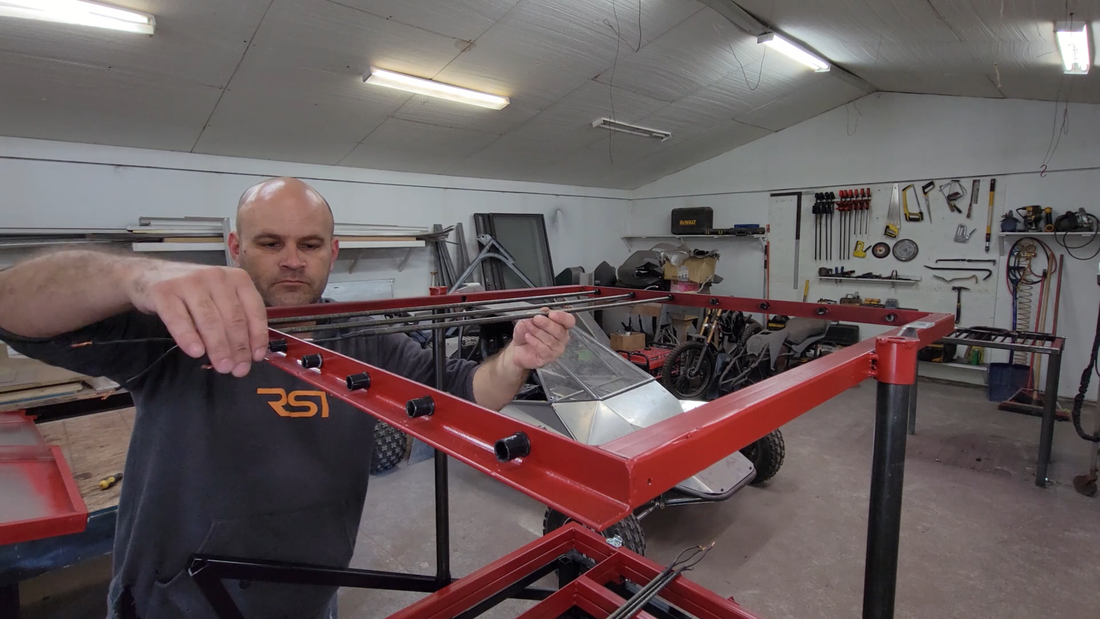
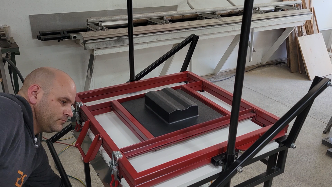
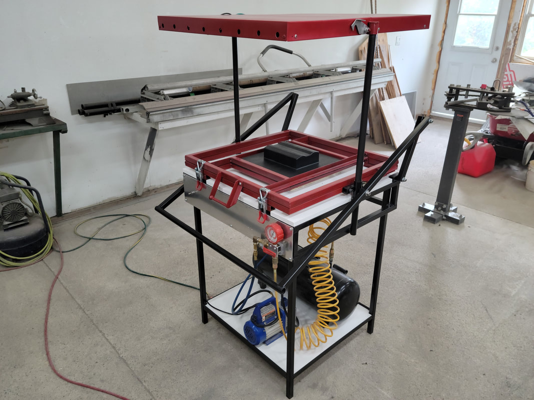
I started the project by making the table frame out of 1x1" steel square tubing. I wanted the former to be large enough to make motorcycle fairings at a later date, so I made the frame to accommodate a 24"x24" forming area inside the platen. Once the table frame was welded together, I installed the legs and guide posts for raising and lowering the platen. In the video you'll notice that I originally used square tubing for the guide posts, but I later switched to round tubing to eliminate the corners and help the platen glide smoother.
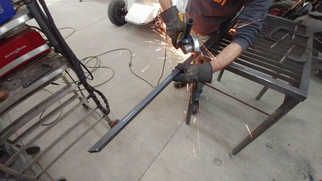
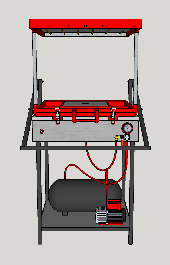
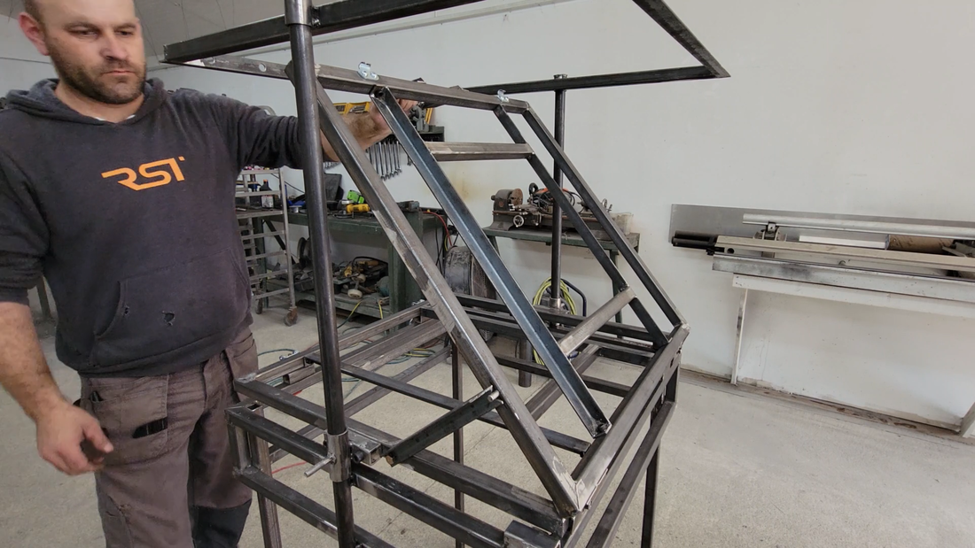
I then made the frame for the oven that mounts at the top of the guide posts. I used steel angle on the front and back to make it easier to drill and mount the heating elements later. The sides were made from square tubing for more strength, as the oven frame will be carrying the weight of the platen when the elements are heating the plastic sheet that's to be formed.
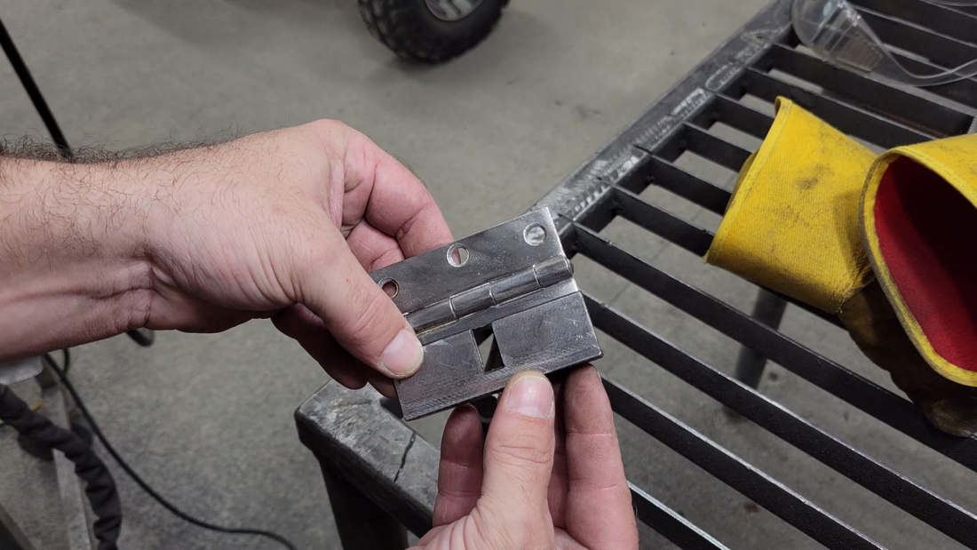
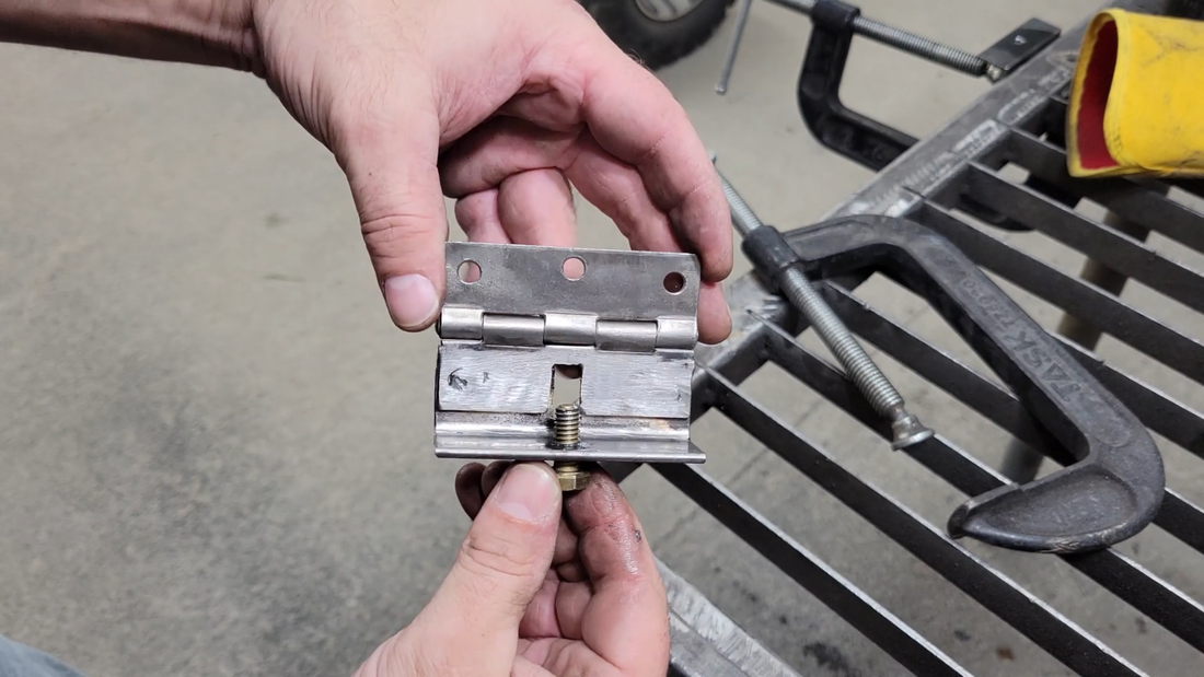
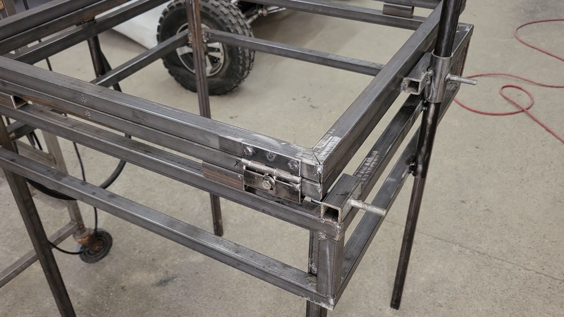
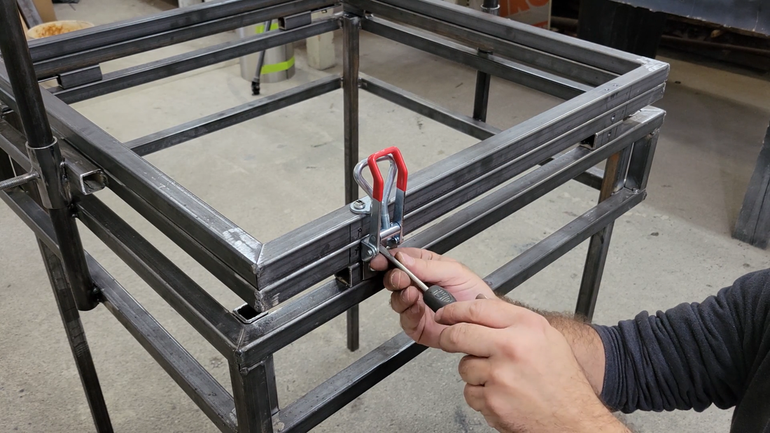
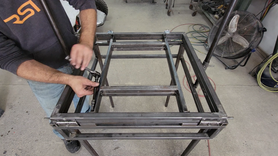
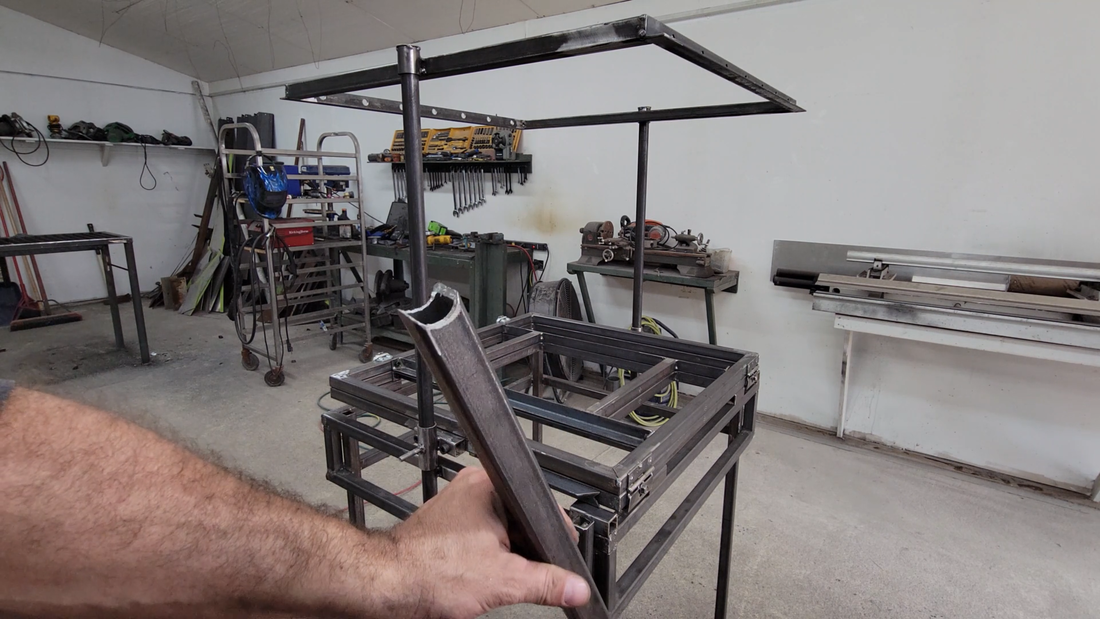
After the top was set, I moved on to making the platen, or clamp, whatever you want to call it. It's the mechanism that will clamp the plastic sheet and hold it in position as it's heated and formed. It's just two simple square frames connected with adjustable hinges on the back to allow for different sheet thicknesses to be clamped without jamming up. I made the hinges using two pre-existing butt hinges for a door and a short piece of angle; the angle was notched in the center on one flange to allow the hinge to move up and down without moving the mounting bolt when it's fastened to the platen, and it's drilled and tapped for a set bolt in the other flange. Together, the two bolts secure the platen to accommodate plastic sheets up to 1/4" thick. Like the oven frame, the platen is connected to the guide posts with DOM tube guides that have a bolt welded on the side for attaching a lifting handle to later. The front of the platen is clamped tight using adjustable toggle latches.
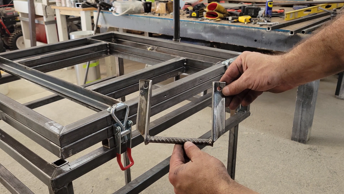
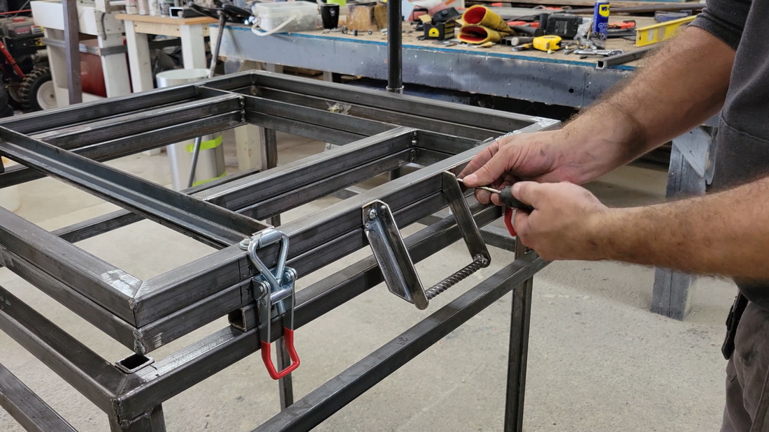
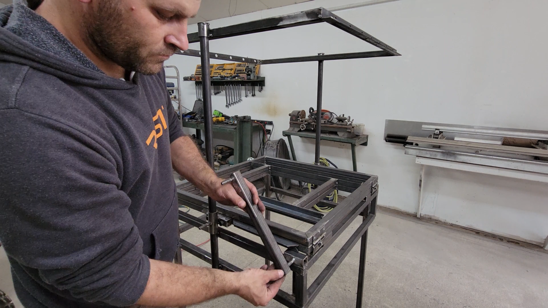
I made a small handle for opening and closing the platen using a couple of short pieces of angle and a thin round bar, as well as a prop to hold it open when needed. I also made a couple of 'reducers' that bolt inside the platen to reduce the forming area and thus plastic waste if I just want to form small objects.
Next, I installed the articulated lifting handle linkages, made from square and round tubing and fastened with 5/16" bolts and lock nuts. Up to this point, I had serious doubts about the platen gliding smoothly because every time I tried to lift it without a handle, it would jam up within the first 6" or so and I'd have to use a hammer to straighten it out. I could see that a lot of the problem was that it was hard to hold the platen level and raise it at the same time - if one hand raised higher than the other, then it jammed. But once the handle was installed, lifting the platen to the oven above and back down became super easy.
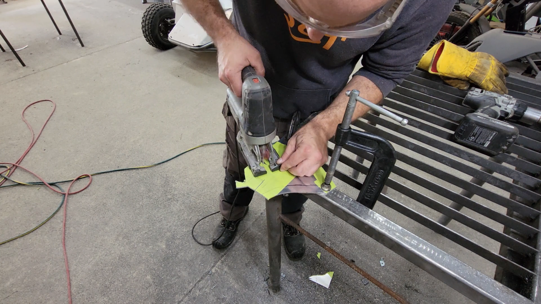
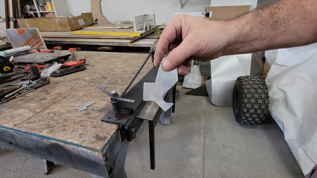
I then made a couple of hooks out of aluminum to fasten to the oven frame that will be used to hold the platen up while the oven heats the plastic for forming. I find that covering the aluminum with masking tape first, then drawing my pattern on top of the tape makes it much easier to cut with a jigsaw. Being a soft metal, aluminum will gum up on the jigsaw blade within minutes of using it, and it'll jam up in the workpiece and be a general pita unless some sort of lubrication is used. WD40, old motor oil, even water will work. But they all create a mess with the shavings. But the adhesive on masking tape seems to do the trick. It warms up when cutting and provides plenty of lubrication for the blade to keep the aluminum from gumming up (surprisingly) and there isn't a big mess to clean up when it's done. I used my recently scratch built sheet metal brake to bend tabs on the hooks that'll make them easier to grab.
The last bit of fabrication left to do was the shield for the oven. The outside is just a simple box that I bent out of 0.026" thick aluminum sheet using my aluminum sheet metal brake, and fastens to the oven frame with self tapping sheet metal screws. I also incorporated inner heat shields to help focus the heat on the plastic and protect the wiring to the elements, and keep the outside shield (or cover I guess) from getting too hot to touch. I later drilled a series of holes in the front and back of the cover to help the wiring chase dissipate heat better.
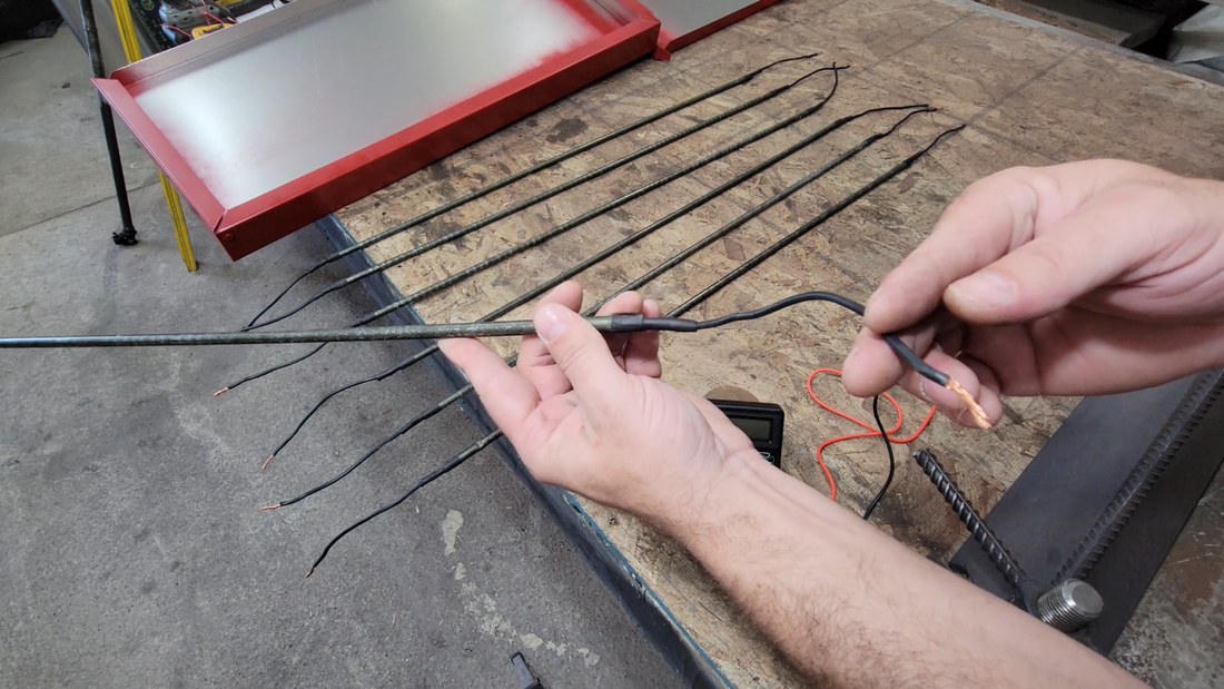
I then took the former apart completely, then sanded, cleaned and painted all of the parts. The next day I began the final assembly and wiring. The elements that I used were salvaged from 220V, 500W electric baseboard heaters. They're tubular elements, like what's used in ovens, some cooking ranges, water heaters, baseboard heaters, etc. I've used them before in my scratch built solar panel laminator and they work great. They're just the right length and power rating for this application.
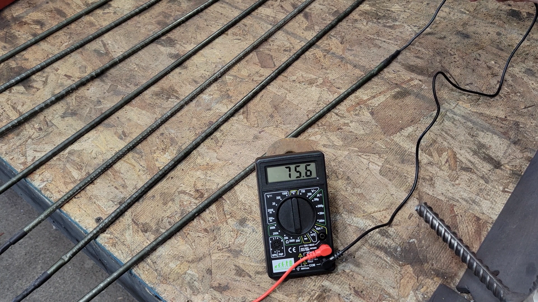
I checked the resistance of the elements with a multimeter set to 'ohms' before I wired them up, just to make sure that I wire the circuit to handle the current that it will be pulling from the 220V split phase main. The resistance for each measured a consistent 75.5 ohms. Current = Volts / resistance, so 220V / 75.5 ohms = 2.9 amps per element. I had 7 elements wired up in the video, so that's a total of 20.3 amps at 220V, or 220 * 20.3 = 4466 watts. I later found this to be too much power for the amount of forming area, and downsized to using just 5 elements. All wiring, switches and plugs in the circuit needed to be sized to handle the current, with an appropriately sized breaker to protect it.
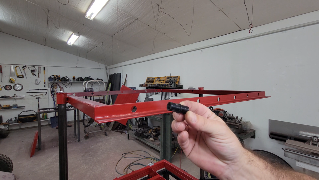
After verifying the resistance, I installed and wired the elements in parallel, and connected them to a double pole, single throw toggle switch. I used rubber grommets where the wires exited the oven cover and entered the guide post to protect them from chaffing.
I checked the resistance of the elements with a multimeter set to 'ohms' before I wired them up, just to make sure that I wire the circuit to handle the current that it will be pulling from the 220V split phase main. The resistance for each measured a consistent 75.5 ohms. Current = Volts / resistance, so 220V / 75.5 ohms = 2.9 amps per element. I had 7 elements wired up in the video, so that's a total of 20.3 amps at 220V, or 220 * 20.3 = 4466 watts. I later found this to be too much power for the amount of forming area, and downsized to using just 5 elements. All wiring, switches and plugs in the circuit needed to be sized to handle the current, with an appropriately sized breaker to protect it.
After verifying the resistance, I installed and wired the elements in parallel, and connected them to a double pole, single throw toggle switch. I used rubber grommets where the wires exited the oven cover and entered the guide post to protect them from chaffing.
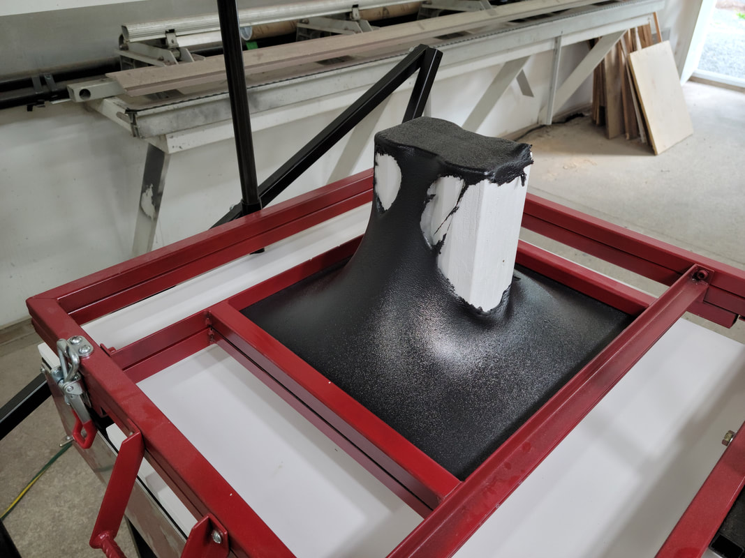
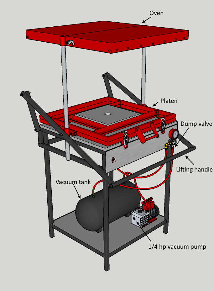
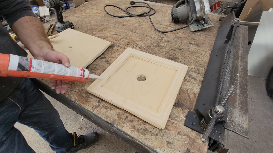
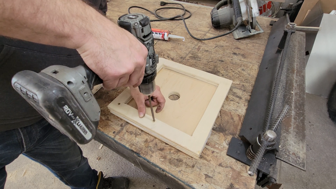
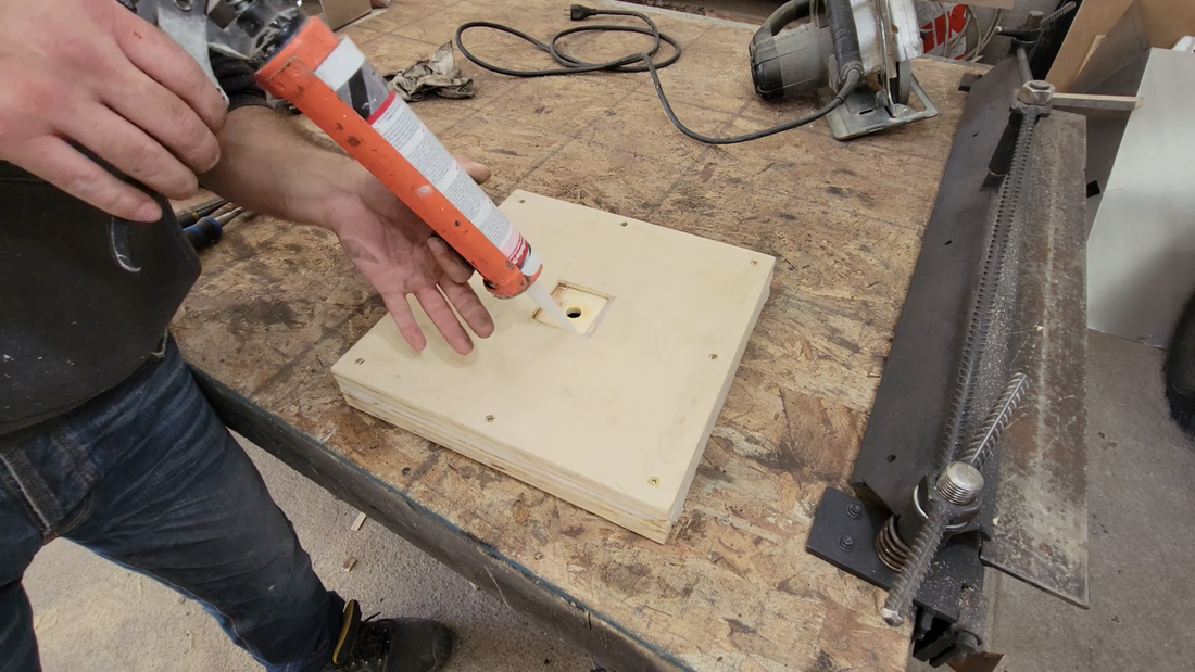
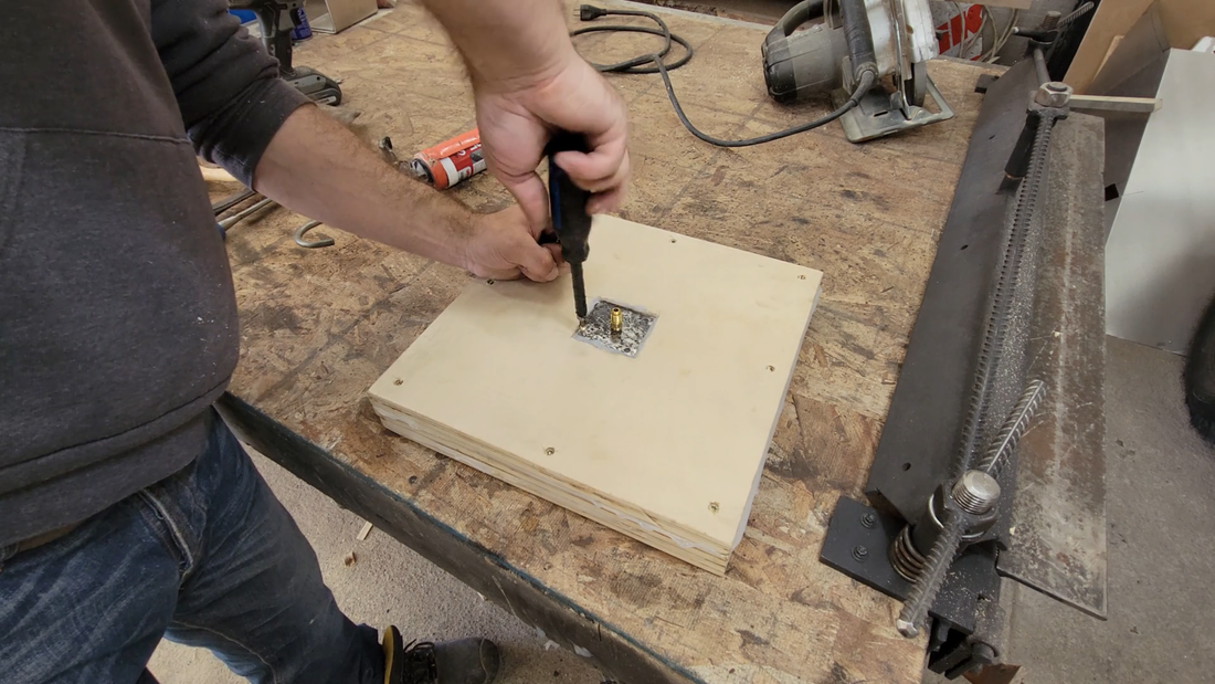
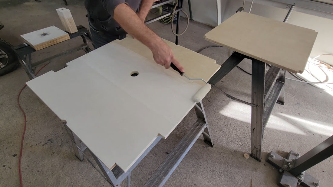
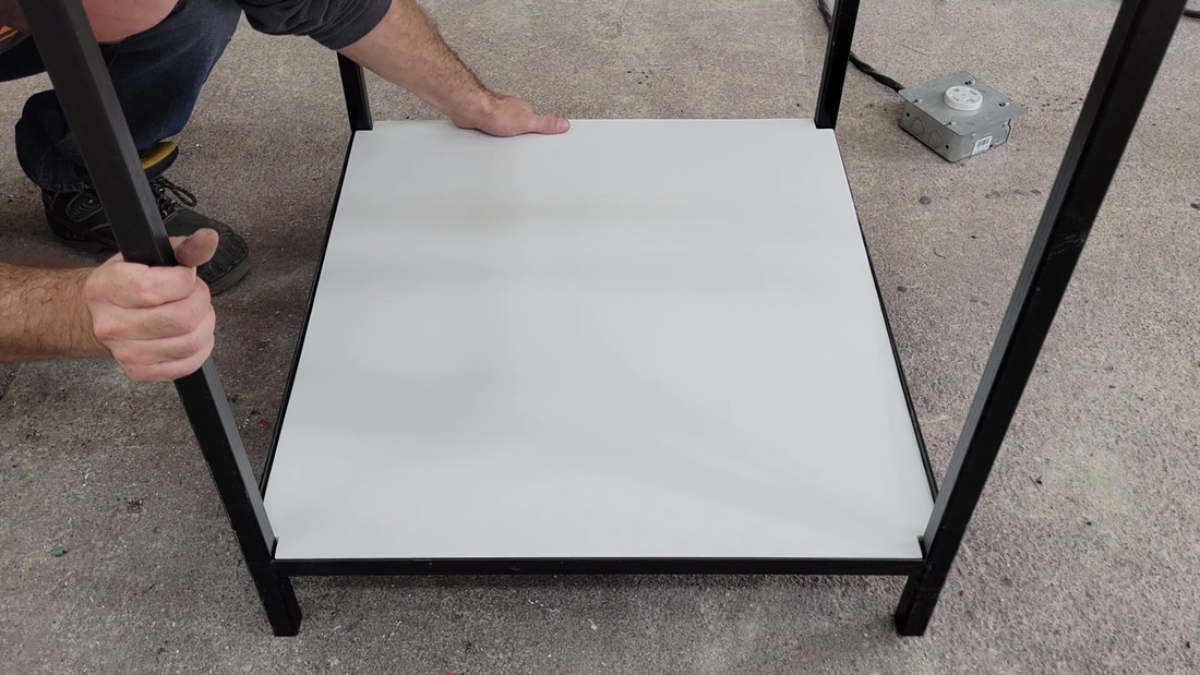
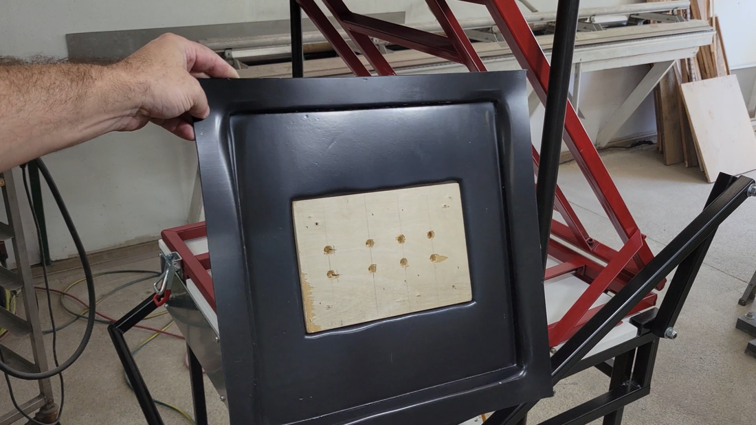
When the wiring was finished, I moved on to making the shelves, table top and plenum from 3/4" thick birch plywood. The plenum is just 3 layers of plywood siliconed and screwed together to form a hollow, sealed box that serves as a platform for the buck (mold) that I'll be forming to and make the connection to the vacuum line. It's approximately 1" smaller (l*w) than the space in the platen, and the top surface is 1" above the plane of the clamped plastic in the platen; this allows me to form a seal between the heated plastic and the edge of the plenum when I lower the platen down to the table to pull a vacuum and form. Without this seal, there is no vacuum. On the bottom side of the plenum I rabbited out a recess for a small 1/4" steel plate with a threaded hole to receive a 1/4" NPT male union which will connect to the vacuum lines. A person can also use barbed fittings and rubber hoses, instead. I used fittings to suit the HVAC charging hoses that I purchased for previous projects.
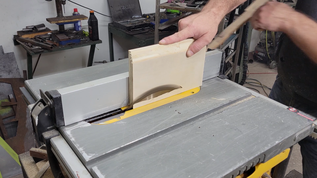
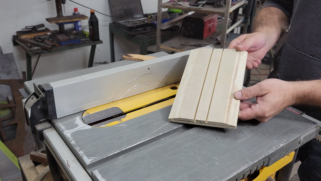
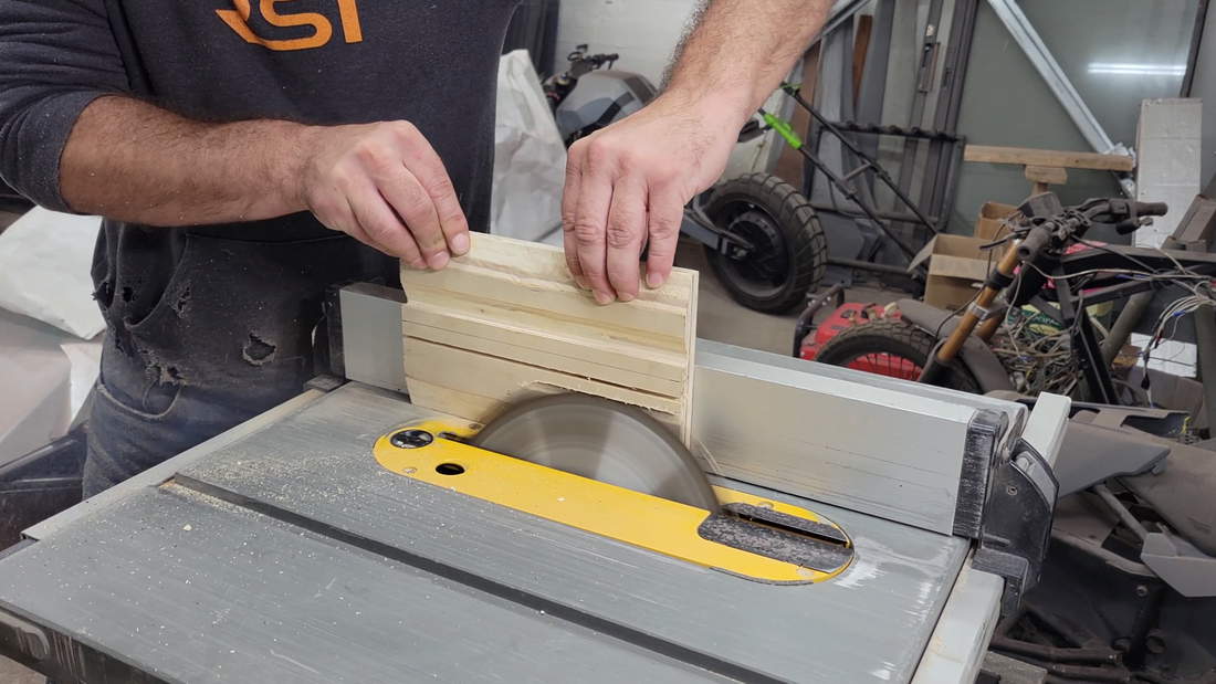
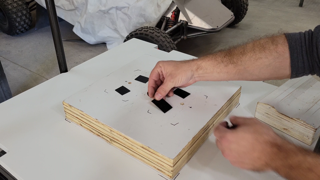
As I mentioned earlier, I built this machine to make cases for the crosskart battery modules. In order to do that, I needed to make a buck that's slightly larger than the size and shape that I want the cases to be. I took measurements of the modules and added 1/8" in all directions. This will help compensate for the plastic naturally shrinking as it cools after it's formed, and provide a little wiggle room for getting the modules into the cases. I then used a table saw and trim router to cut and shape a plywood buck accordingly. I primed and painted the wooden components and then installed them with the vacuum system.
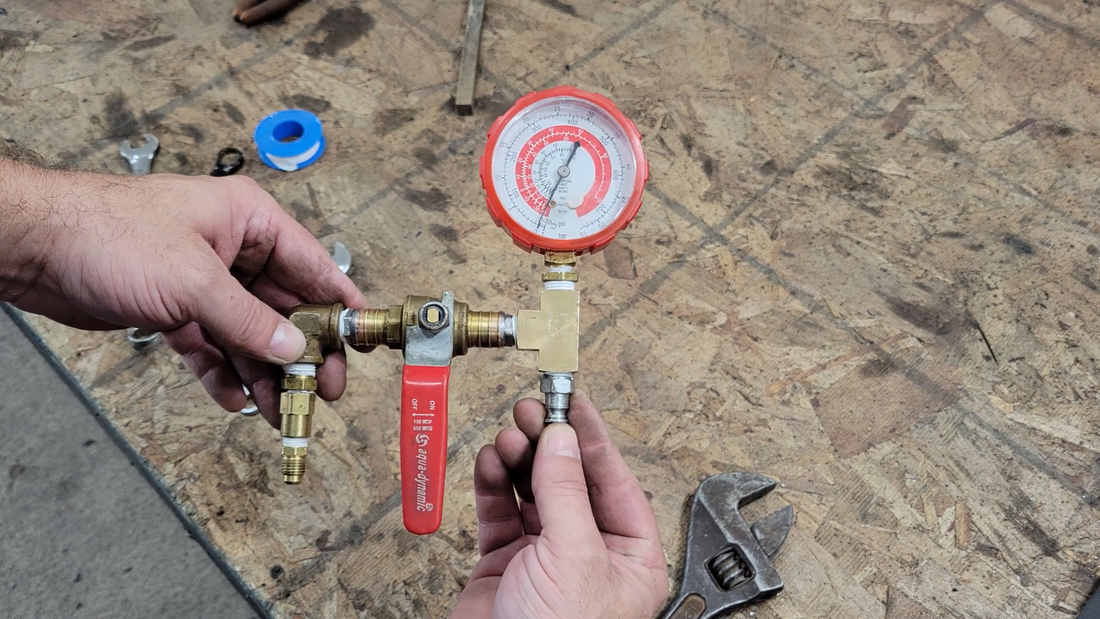
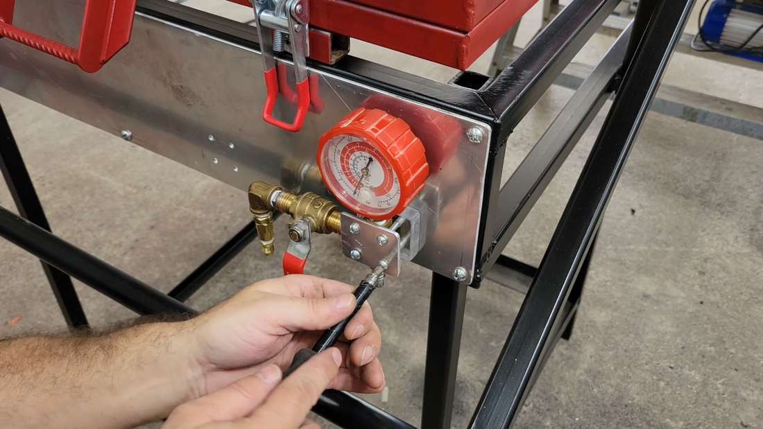
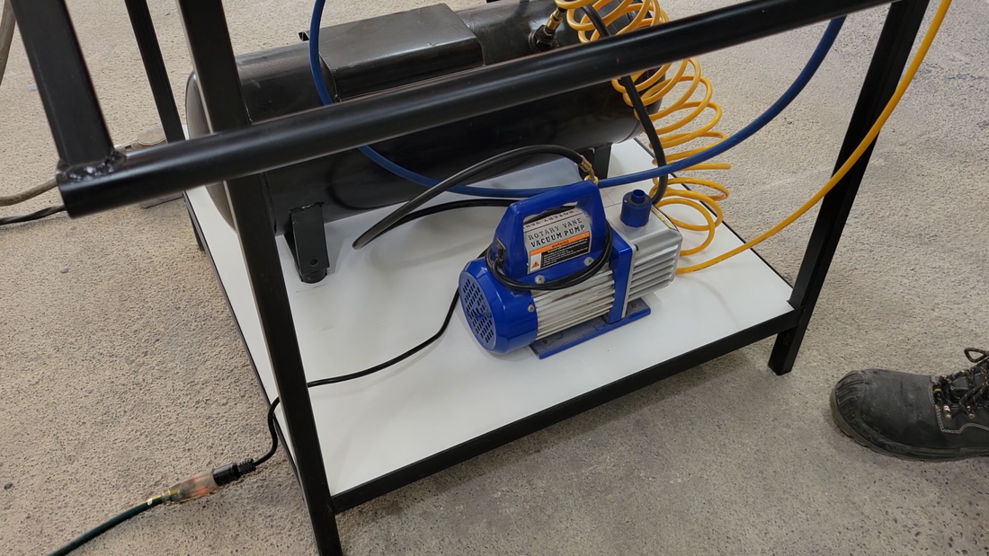
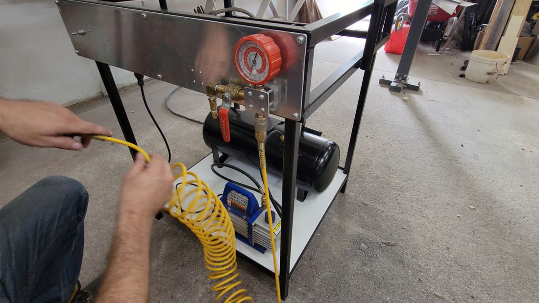
I used a 1/4 hp single stage rotary vacuum pump, which seems to work just fine. I connected it to an 8 gallon air tank, and the air tank was connected to ball valve and negative pressure gauge. The ball valve is connected to the plenum under the buck. The ball valve, or 'dump' valve, is used to dump the air trapped under the heated plastic sheet after it's stretched over the buck, into the tank below to create a vacuum and pull the plastic to its final shape.
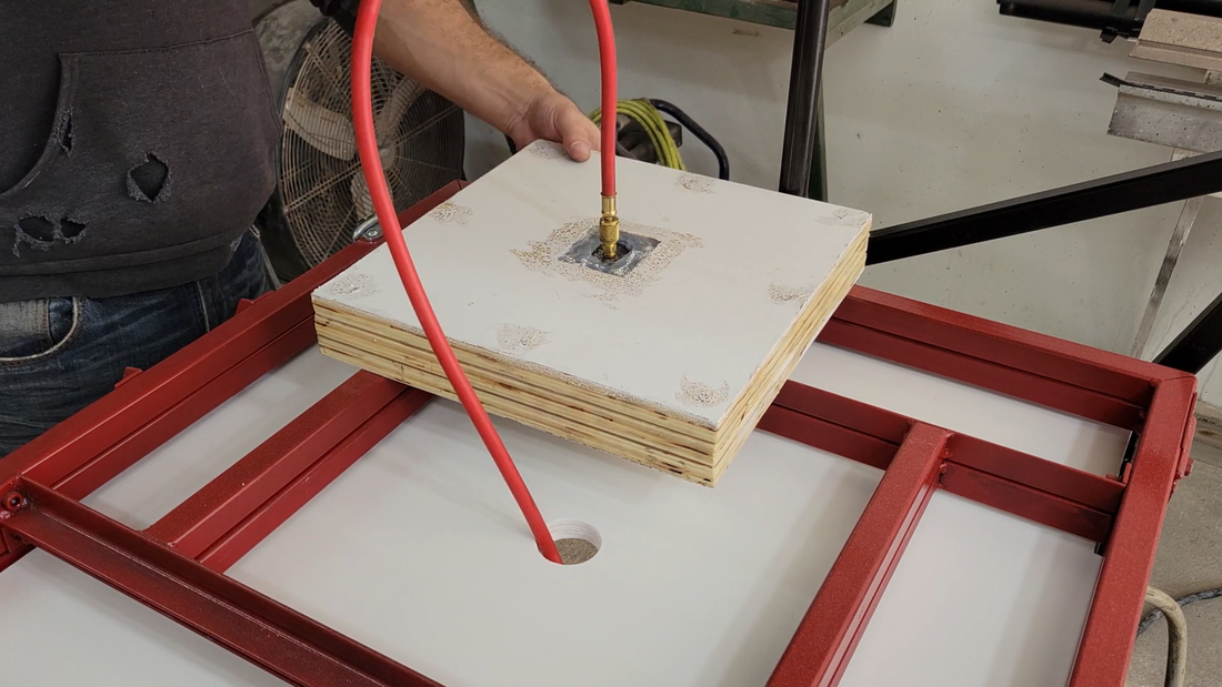
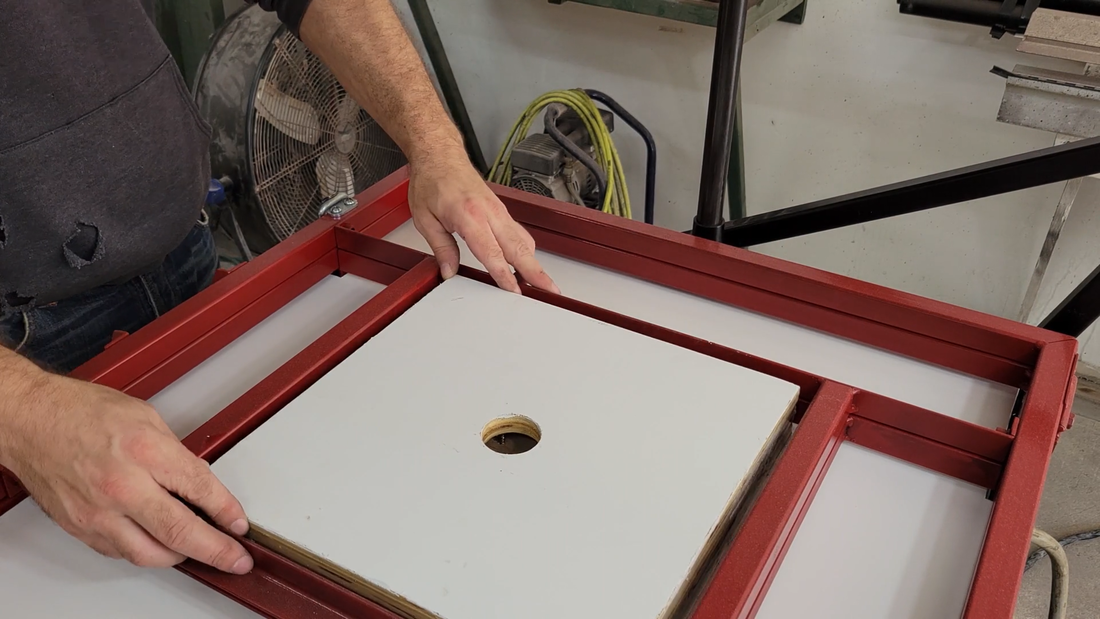
Once the vacuum system was hooked up, it was ready to form. I turned on the vac pump to pull a vacuum in the tank, then clamped a sheet of 1/16" thick ABS plastic in the platen, raised it and turned on the oven. Then I set the buck on the plenum with a small piece of 1/16" thick plastic under each corner to keep it elevated enough for the vacuum to pull around all the edges of the buck and into the hole below it.
I periodically checked the temperature of the oven every 30-60 seconds, making sure that it doesn't overheat and burn the ABS. It's important to not let the elements and plastic get too hot, not just because of a fire hazard but also because the plastic won't form properly if it's not the right temperature. For ABS I found that ~150°C was the sweet spot. The glass transition point is ~110°C, which is when it starts to become soft and rubbery. The melting point is ~200°C. This is too hot, as you'll see from my fails in the video. The ABS becomes too runny and can't hold its form. It also begins to smoke and boil, creating air bubbles that weaken it. It gets hottest in the center of the plastic first, and the edges lag behind. The hotter the elements operate, the bigger the difference between the center and edges of the plastic and the greater the risk of overheating the plastic. I found that turning the elements off when they begin to glow red at around 300-350°C was optimal for heating the plastic to forming temperature quickly but relatively evenly. I'll be incorporating a PID controller and thermocouple later to keep the temperature under control.
I periodically checked the temperature of the oven every 30-60 seconds, making sure that it doesn't overheat and burn the ABS. It's important to not let the elements and plastic get too hot, not just because of a fire hazard but also because the plastic won't form properly if it's not the right temperature. For ABS I found that ~150°C was the sweet spot. The glass transition point is ~110°C, which is when it starts to become soft and rubbery. The melting point is ~200°C. This is too hot, as you'll see from my fails in the video. The ABS becomes too runny and can't hold its form. It also begins to smoke and boil, creating air bubbles that weaken it. It gets hottest in the center of the plastic first, and the edges lag behind. The hotter the elements operate, the bigger the difference between the center and edges of the plastic and the greater the risk of overheating the plastic. I found that turning the elements off when they begin to glow red at around 300-350°C was optimal for heating the plastic to forming temperature quickly but relatively evenly. I'll be incorporating a PID controller and thermocouple later to keep the temperature under control.
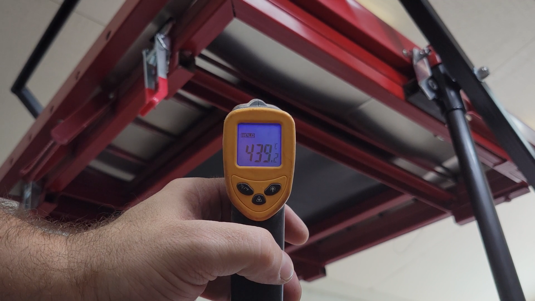
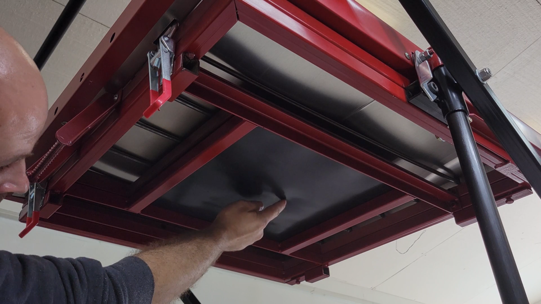
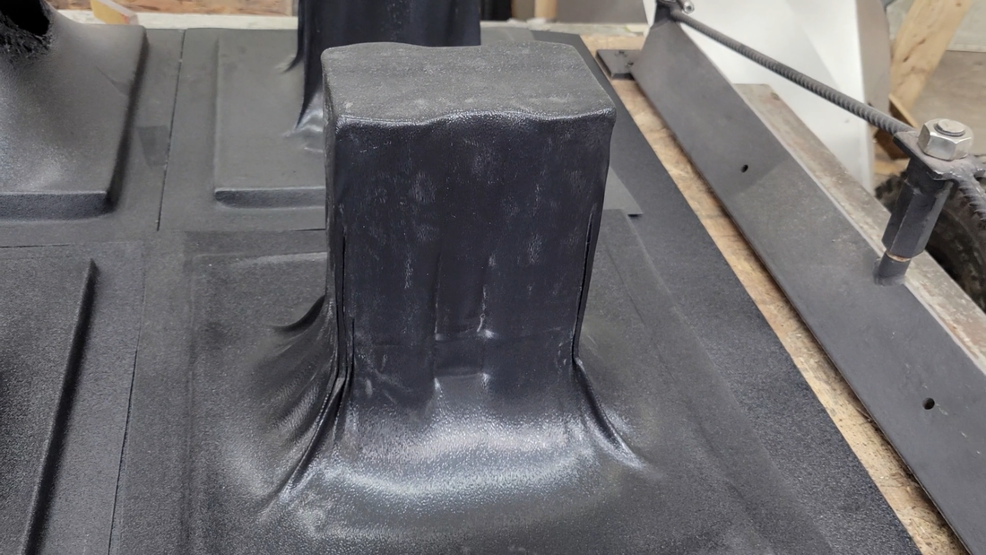
The heating process takes just 4 to 4 1/2 minutes to complete. You can tell it's ready when the center of the plastic begins to droop and becomes rubbery to touch, kind of like a tire tube. This is the perfect time to drop it and pull the vacuum. When the platen is lowered, I make sure to force it all the way to the table to get a good seal around the edges of the plenum before opening the ball valve. I let the pump pull a vacuum for around 1-2 minutes afterward, until the plastic has cooled enough to unclamp it. But a person needs to move fast once the plastic is removed from the heat because it begins to cool quick, and a 5-10 second delay could mean the difference between a good vacuum pull and a half formed piece that solidified before it was finished. The thinner the plastic is, the faster it cools.
As mentioned earlier, the plastic is also going to shrink a bit as it cools. That means the longer it stays on the buck after forming, the tighter it clamps to it and the harder it'll be to remove the buck after without damaging the workpiece. The buck should be removed as soon as the plastic is cool enough to handle.
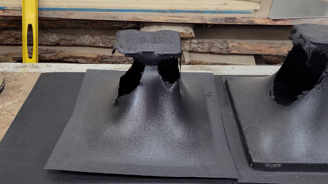
Another thing to keep in mind is that when the plastic is stretched over the buck when the platen is dropped, it becomes thinner. It's a good idea to use slightly thicker material than what you plan the formed piece to be to compensate. The deeper the draw, the more the plastic will stretch and thin. I learned this the hard way when I first started forming. My original buck for the battery cases was tall so that I could form all the sides and bottom at once. However, this didn't work out well for the 1/16" thick ABS because it thinned too much and kept tearing open. So I switched to forming two halves for the sides and bottom, and a separate cap for the top. After forming, the parts were trimmed and assembled using ABS solvent cement. It was an extra couple of steps that I wasn't counting on, but they turned out great regardless. I'm super happy with this project. I'll show you how I made the battery modules and assembled the cases in the next video.
As mentioned earlier, the plastic is also going to shrink a bit as it cools. That means the longer it stays on the buck after forming, the tighter it clamps to it and the harder it'll be to remove the buck after without damaging the workpiece. The buck should be removed as soon as the plastic is cool enough to handle.
Another thing to keep in mind is that when the plastic is stretched over the buck when the platen is dropped, it becomes thinner. It's a good idea to use slightly thicker material than what you plan the formed piece to be to compensate. The deeper the draw, the more the plastic will stretch and thin. I learned this the hard way when I first started forming. My original buck for the battery cases was tall so that I could form all the sides and bottom at once. However, this didn't work out well for the 1/16" thick ABS because it thinned too much and kept tearing open. So I switched to forming two halves for the sides and bottom, and a separate cap for the top. After forming, the parts were trimmed and assembled using ABS solvent cement. It was an extra couple of steps that I wasn't counting on, but they turned out great regardless. I'm super happy with this project. I'll show you how I made the battery modules and assembled the cases in the next video.
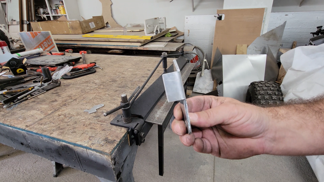
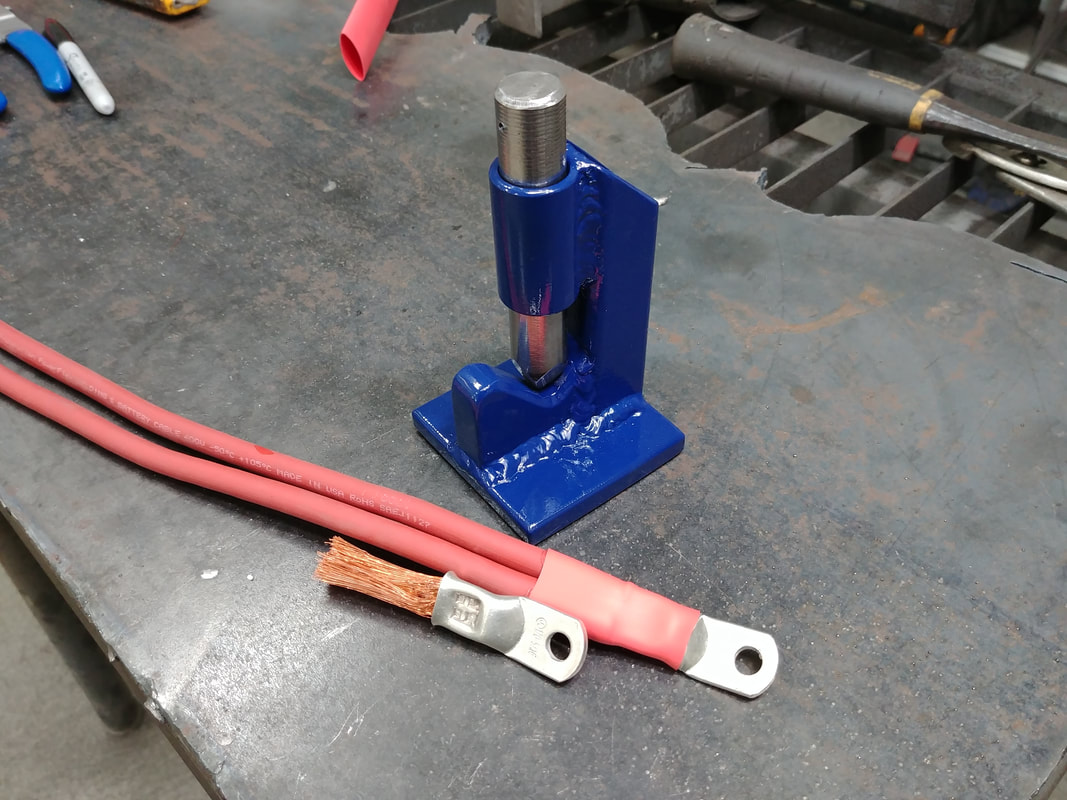
Hey folks. I've just got a quick build video for you today. In this one, I make a hammer crimper for crimping lugs to the cables that I'm using for the electric crosskart battery.
A hammer crimper is a pretty common tool and is reasonably affordable, costing around $30-$50. But, most of you know what I'm about. Why spend the $ and wait 2-3 weeks for delivery when I can make it out of scraps in 20-30 minutes and get straight to work crimping cables? So let's do it.
A hammer crimper is a pretty common tool and is reasonably affordable, costing around $30-$50. But, most of you know what I'm about. Why spend the $ and wait 2-3 weeks for delivery when I can make it out of scraps in 20-30 minutes and get straight to work crimping cables? So let's do it.
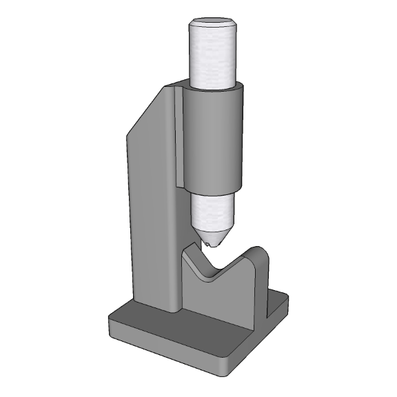
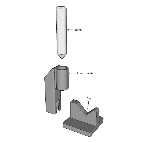
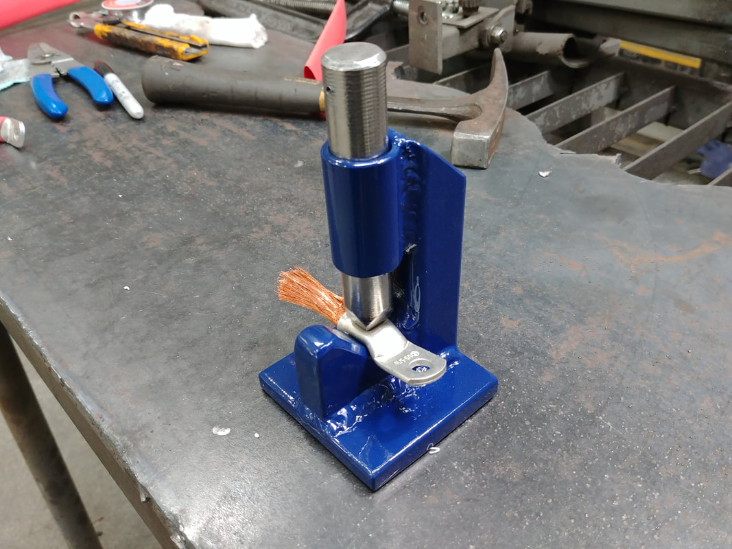
The design is really simple, I almost don't need to explain anything about it, but I will just to say I did. The first thing that I did was mark out the die profile onto a piece of 1/2" mild steel flat bar, then center punched and drilled a 3/8" diameter hole where the lug will rest on the form as it's crimped. I then made two cuts at 45° angles on either side of the 3/8" hole cut to form a 'birds mouth' and beveled the edges slightly with an angle grinder. I chose 1/2" steel because it's a good thickness for the length of the 1/0 lugs that I'll be crimping - it provides a good surface area to support the bottom tube portion of the lug while it's being hammered on without affecting the bolt flange. A person could crimp 4 awg cable or greater with this tool, though a punch with a narrower end will be necessary for smaller gauges.
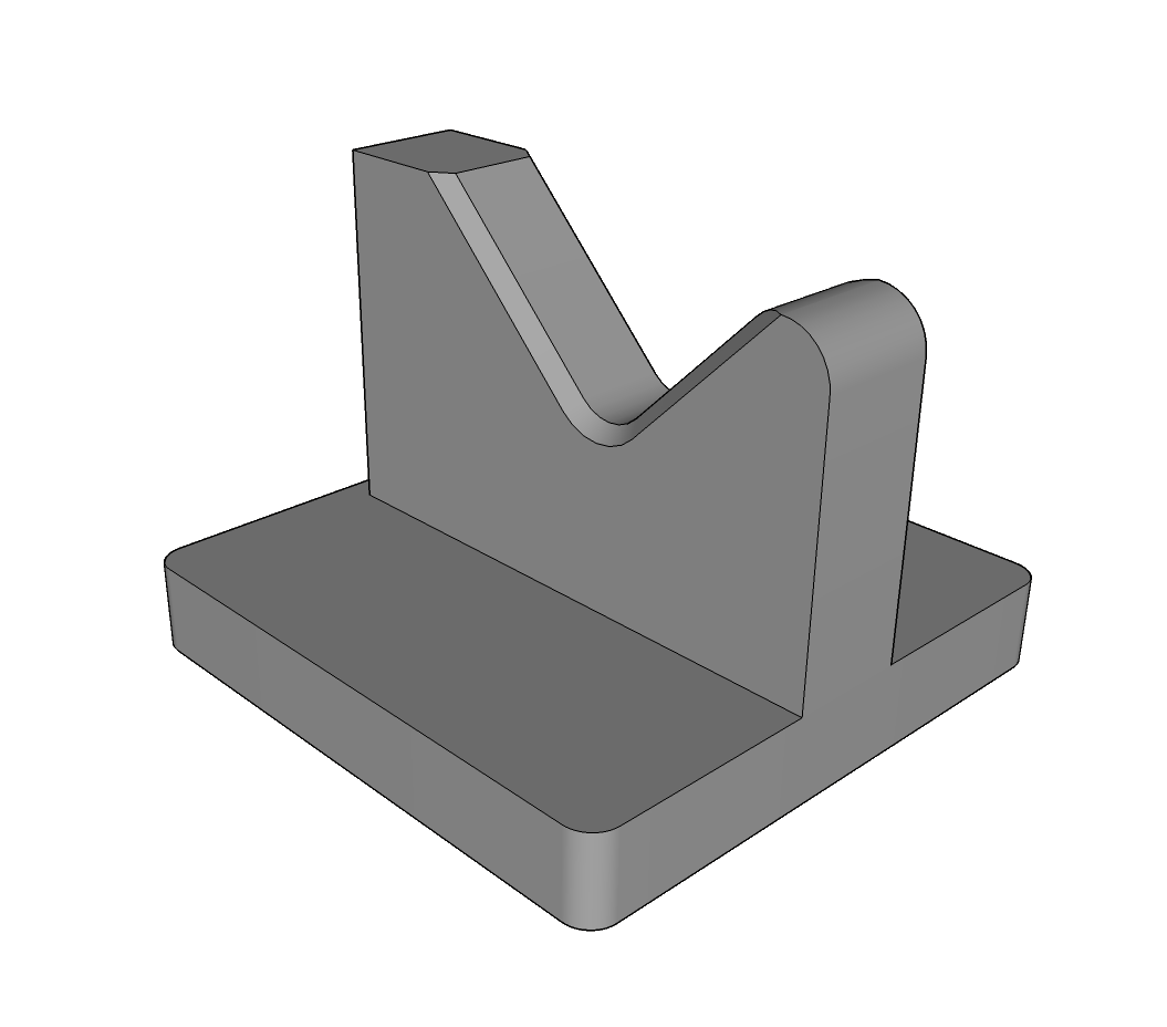
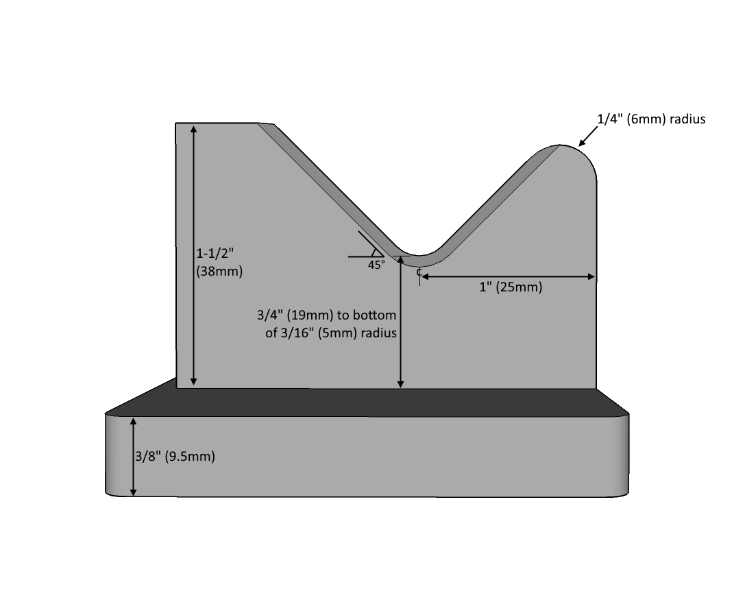
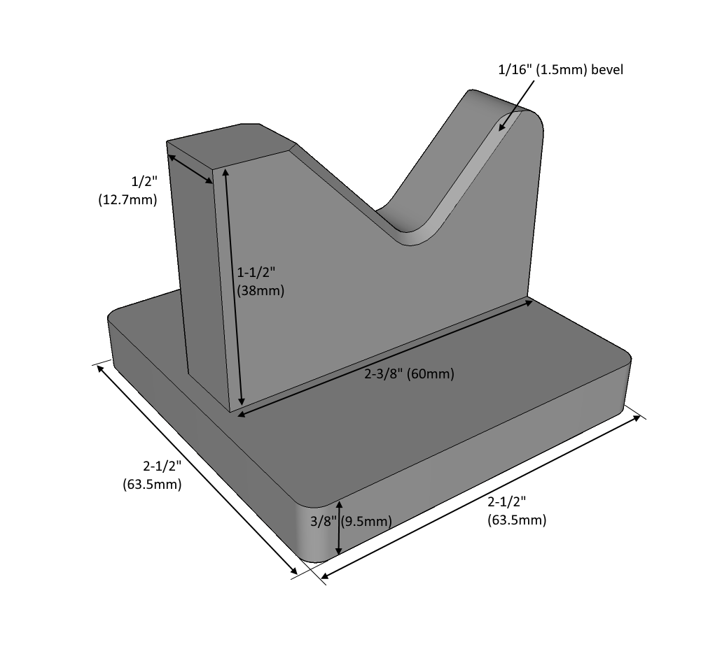
After the form was cut and drilled, I made a simple 2.5" square base to weld it to using 3/8" mild steel plate.
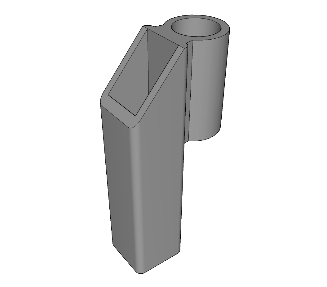
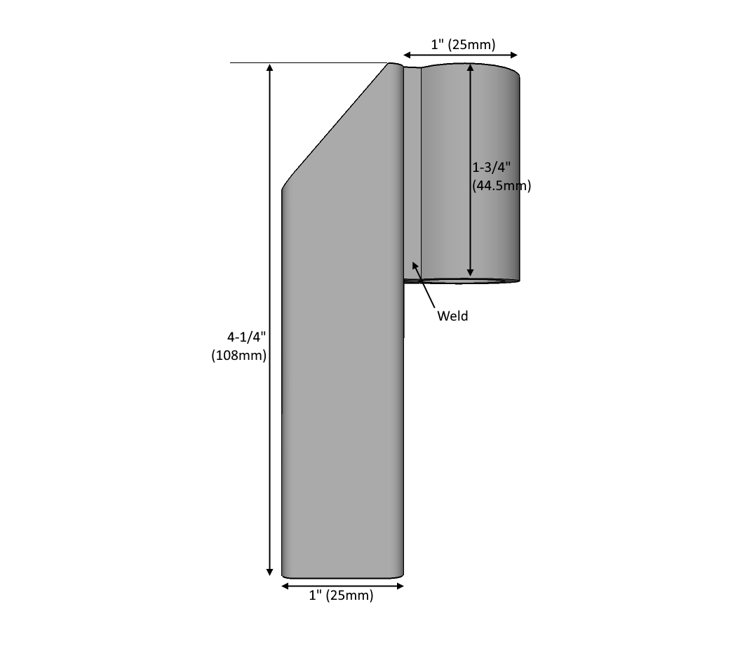
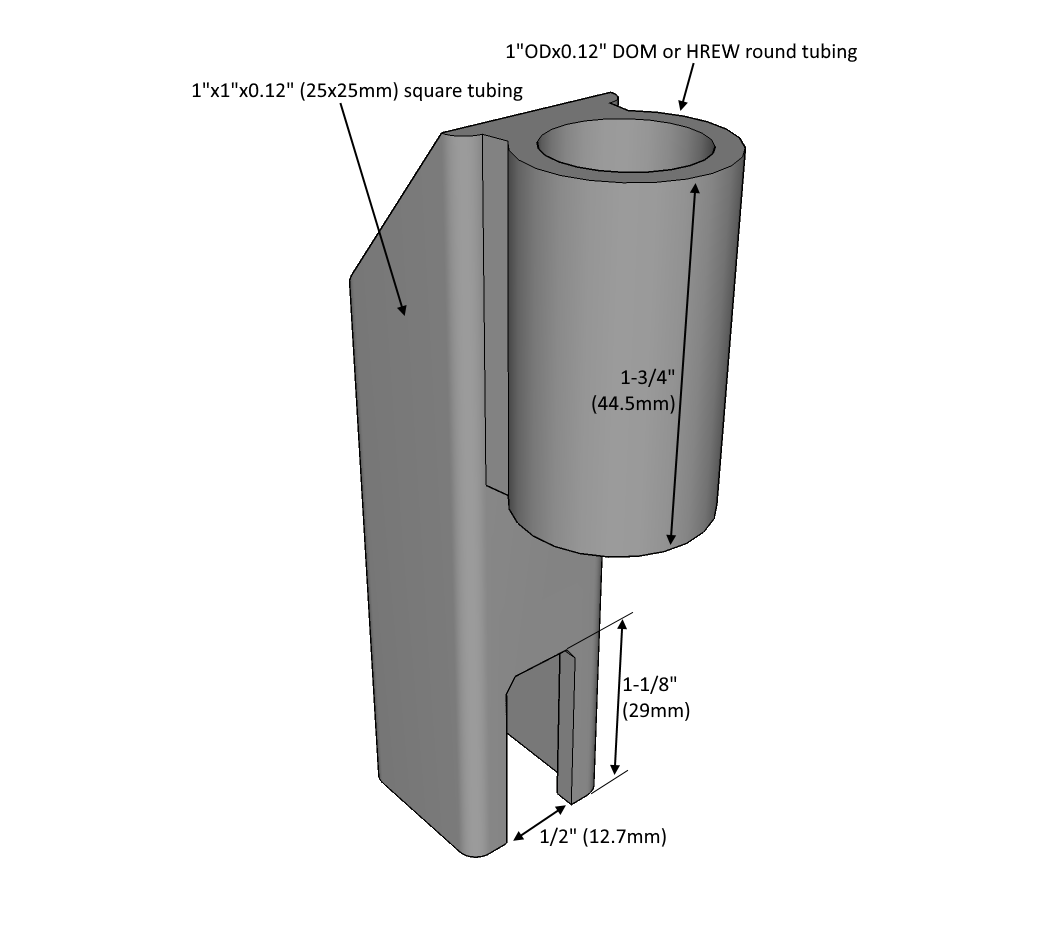
Next, I cut up an old rusty piece of 1x1" square tubing and 1"x0.12" HREW round steel tubing as shown below. These will be the carrier, so to speak, for the punch (plunger, whatever you want to call it). The square tubing was notched in the bottom to receive the form base, but not before it was welded to the round tubing. The only thing that's important to ensure is that the center of the round tubing ends up centered with the form below it, otherwise the crimping will be buggered up and off-centered, and may not provide sufficient holding power on the cable to prevent them from pulling apart later.
Next, I cut up an old rusty piece of 1x1" square tubing and 1"x0.12" HREW round steel tubing as shown below. These will be the carrier, so to speak, for the punch (plunger, whatever you want to call it). The square tubing was notched in the bottom to receive the form base, but not before it was welded to the round tubing. The only thing that's important to ensure is that the center of the round tubing ends up centered with the form below it, otherwise the crimping will be buggered up and off-centered, and may not provide sufficient holding power on the cable to prevent them from pulling apart later.
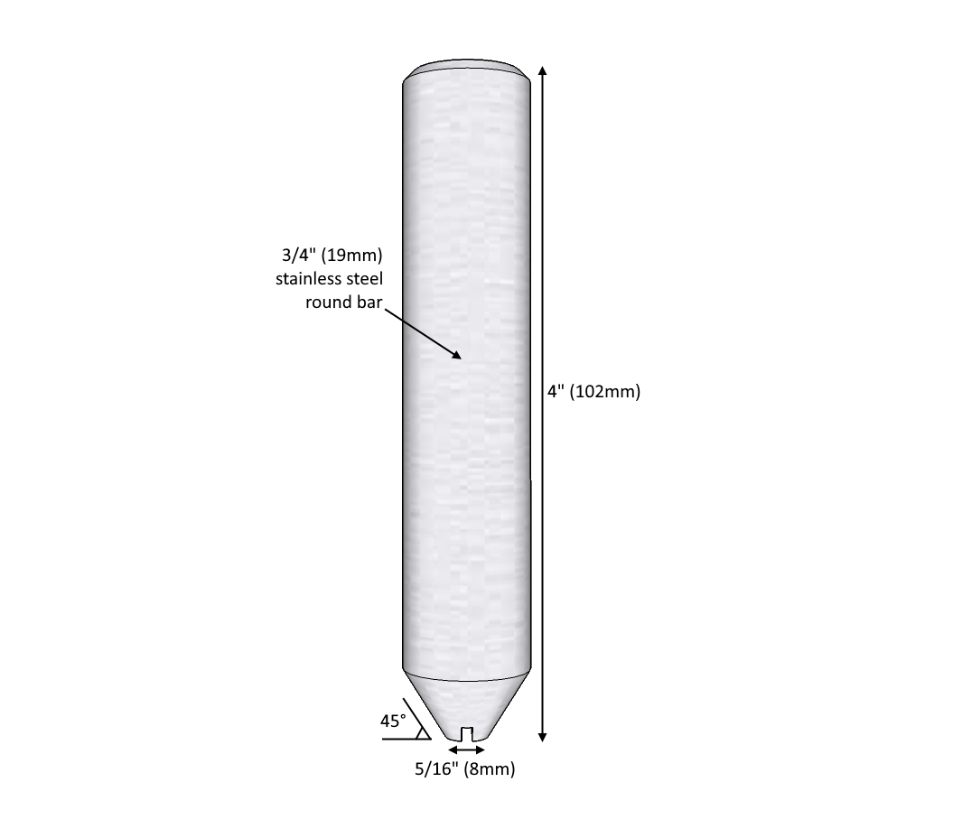
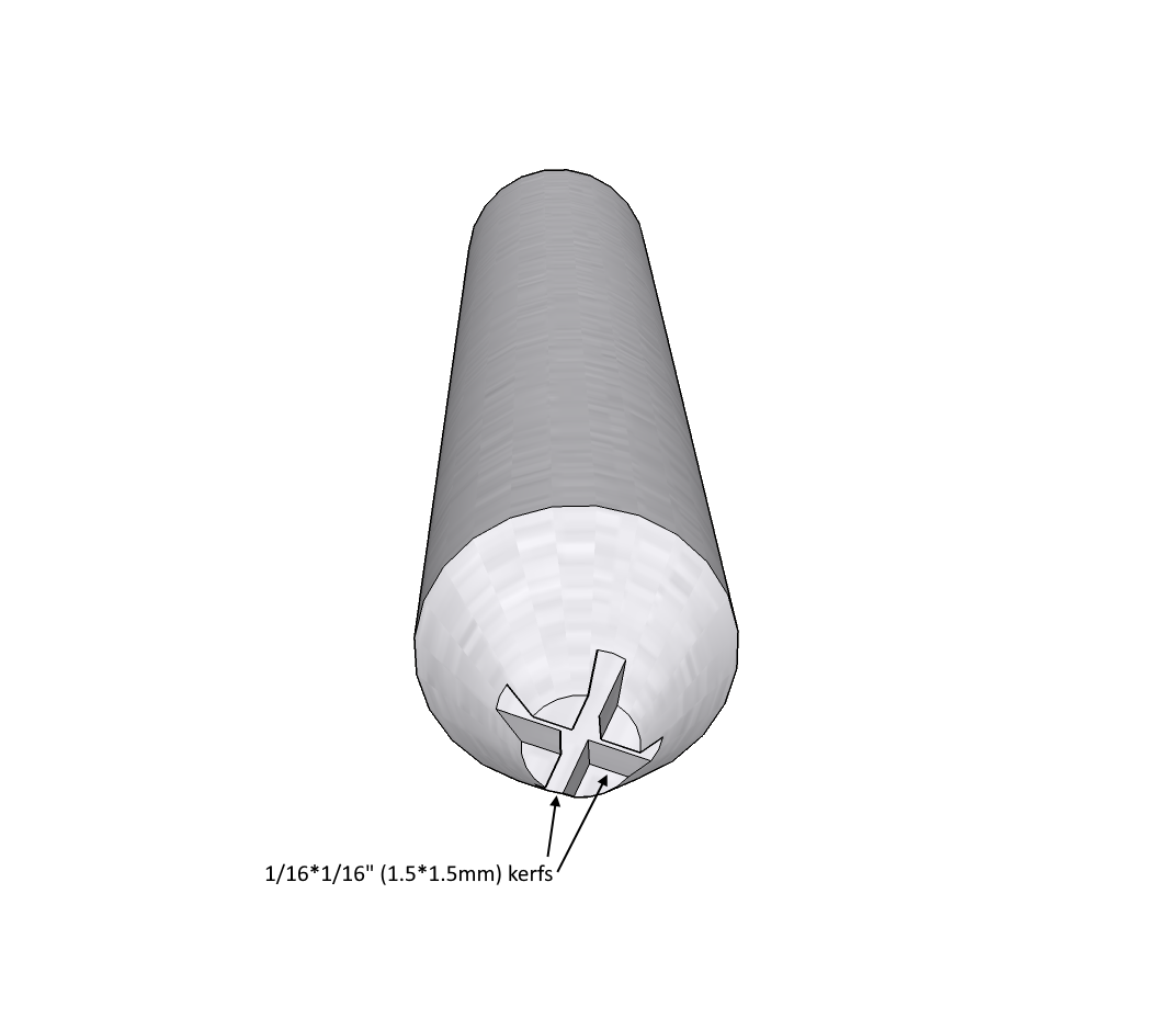
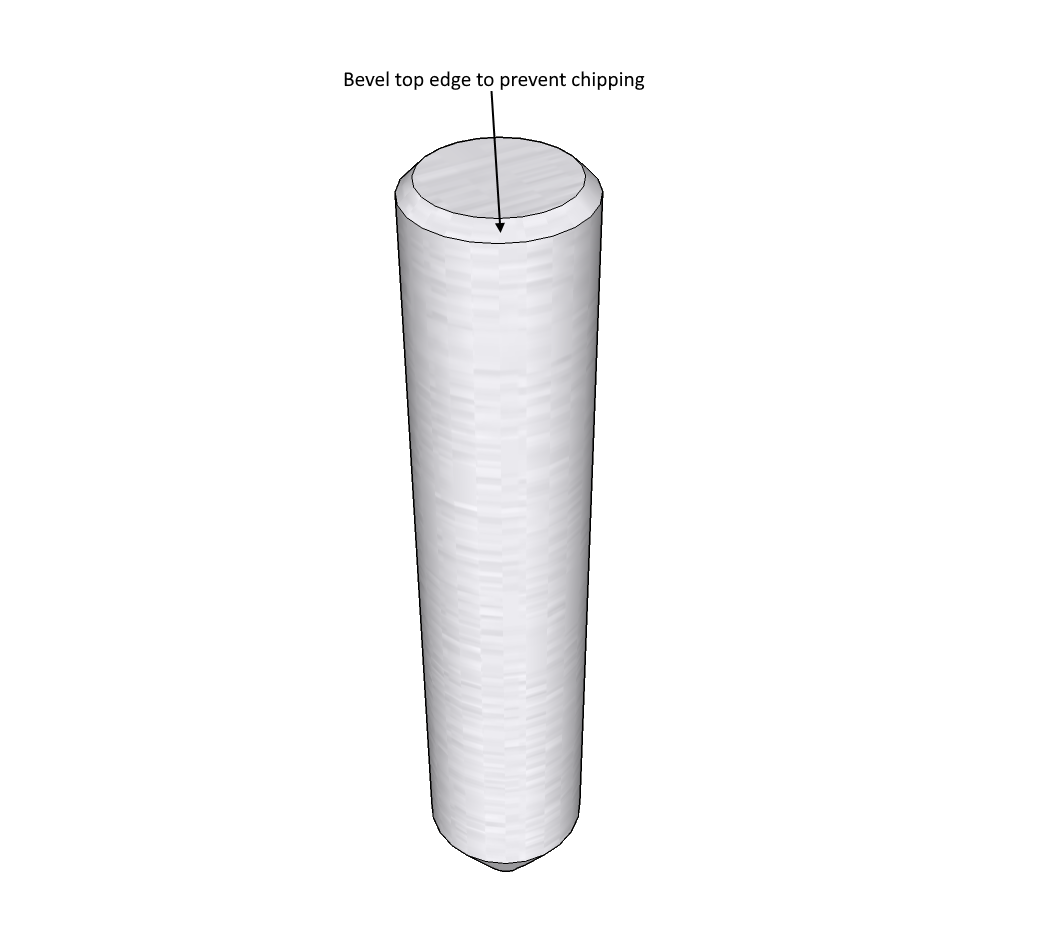
The super easy bit was making the punch. It's just a 4" long piece of 3/4" stainless steel round bar with 45° bevels on the bottom narrowing to a 5/16"x5/16" square end that has two crisscrossing kerfs cut into the face, approximately 1/16" deep. Resembling the end of a fat, inverted Phillips head screwdriver. These kerfs will transfer into the lug when it's crimped to provide better gripping power on the cable. The top end of the punch was beveled slightly to help prevent chipping the edges when it's being hammered.
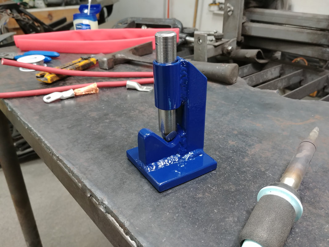
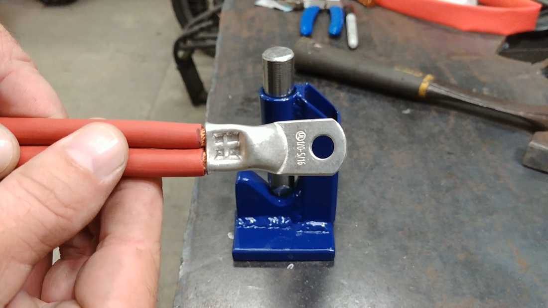
A coat of spray paint later and the crimper was done. It works great for crimping two 4 awg cables into a 1/0 lug (the reason why I'm using two cables instead of one is explained in the crosskart blog). A few good whacks with a 20oz hammer is all it takes. The end result looks and functions as I would expect. I haven't load tested them, of course, but if the strands are crushed to the point of resembling a solid piece of copper and I can't pull them apart with a pair of pliers, then there's a pretty good chance the connection is fine and they won't work themselves loose in the battery case.
A few side notes about crimping copper lugs to battery cables. There seems to be some debate about whether to solder the connection or not. Some people believe solder is the only way, while others believe crimping is superior. There's nothing wrong with soldering your lugs, if you have the means to provide enough heat to do so without damaging the cable insulation. That's the problem with soldering. It makes a solid, sealed connection that won't corrode (as long as you use rosin flux and not acid flux), but the thicker the cable is the more heat it takes to solder until you get to a point where a standard soldering iron isn't up to the task. I'm pushing it with the 4 awg cable and 200W iron. If I had to use 1/0 cable, I would probably need to use a blow torch on the lug and cable end - I don't think that would work out too well if I expect to keep the insulation as close to the joint as possible.
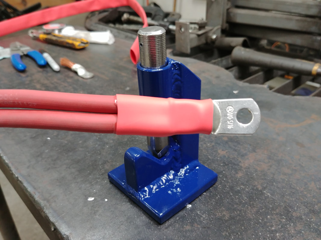
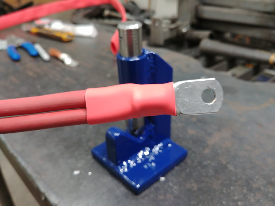
Crimping will provide a bond that's as strong if not stronger than solder in some cases, but if tinned copper cable isn't used (which is expensive), then some precaution needs to be taken to prevent the cable from corroding later, which all copper does when it's exposed to air. You can sand it clean and shiny, but within a year it will turn green and likely affect the connection if the mating surfaces aren't married perfectly. The first thing to do to prevent this is to use tinned copper lugs, not bare copper lugs. Tinned copper lugs have, of course, a coating of tin on them to seal the copper from the air. The next thing you should use to protect the connection is heat shrink tubing. But not just any kind - you need the stuff that has a layer of glue on the inside surface. It's like hot glue, when heated this will make the final seal between the shrink tubing and the cable/lug connection.
That's all you need to do. Most electricians just crimp their battery cable lugs. When done properly you can count on the connections to last longer than the battery itself.
I'll have the next video for the crosskart build series uploaded in roughly a week, give or take a couple of days. I'll be assembling the P groups for the 11.5 kWh LiFePo4 battery and test fitting them in the crosskart cabin with aluminum cases and the new bucket racing seat from Scat.
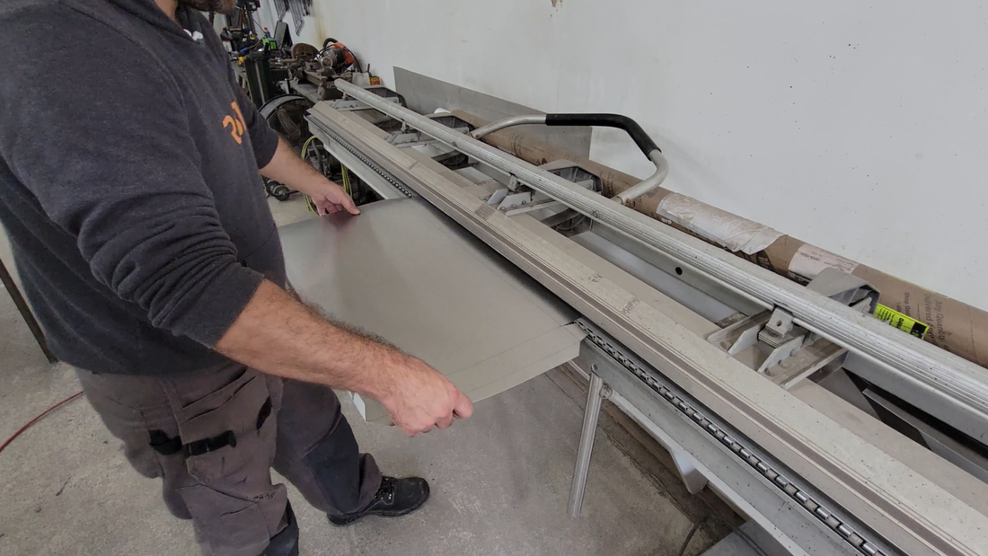
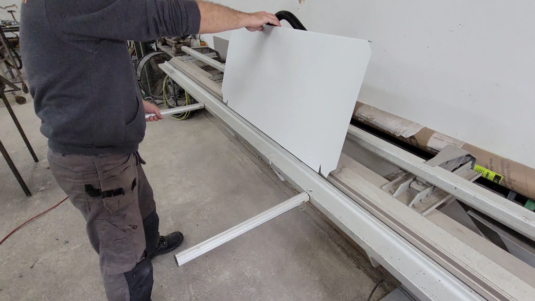
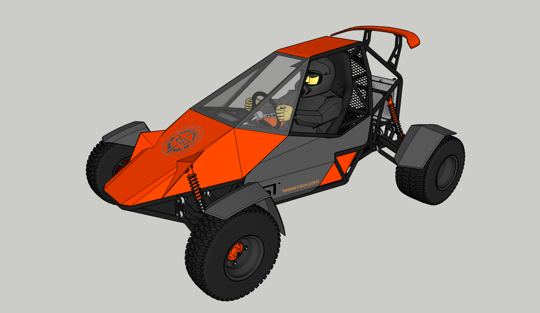
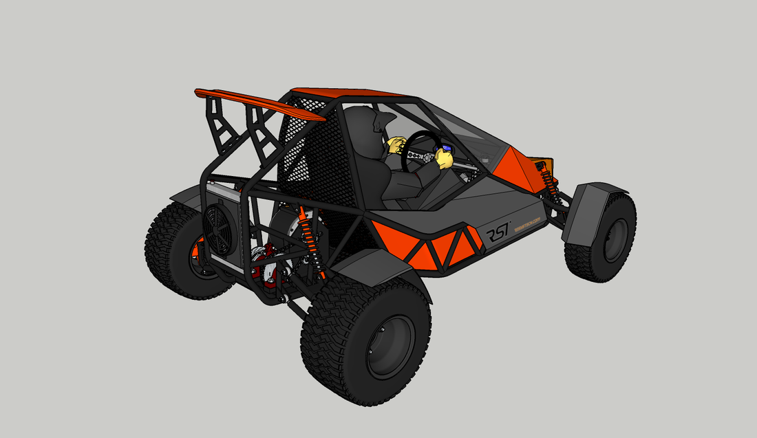
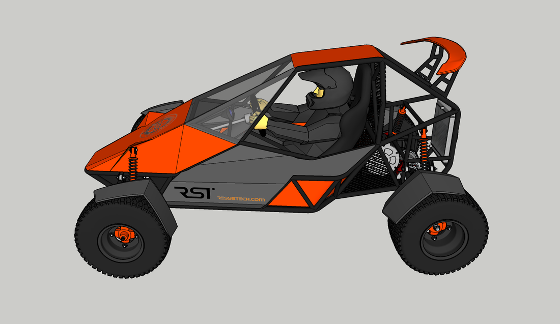
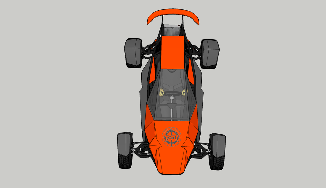
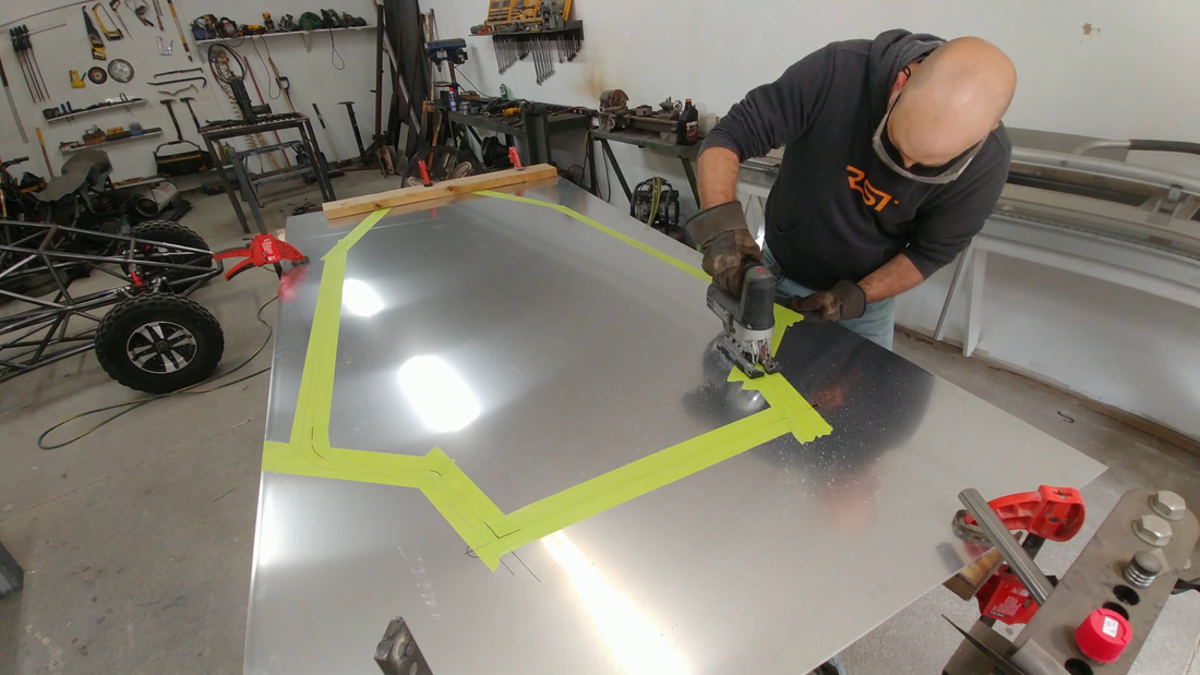
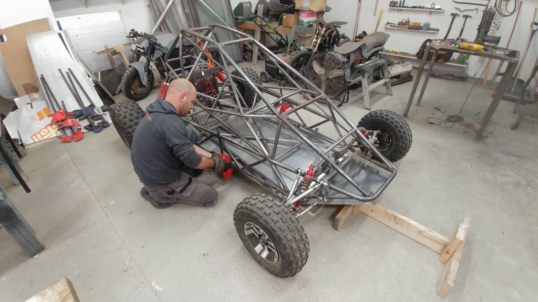
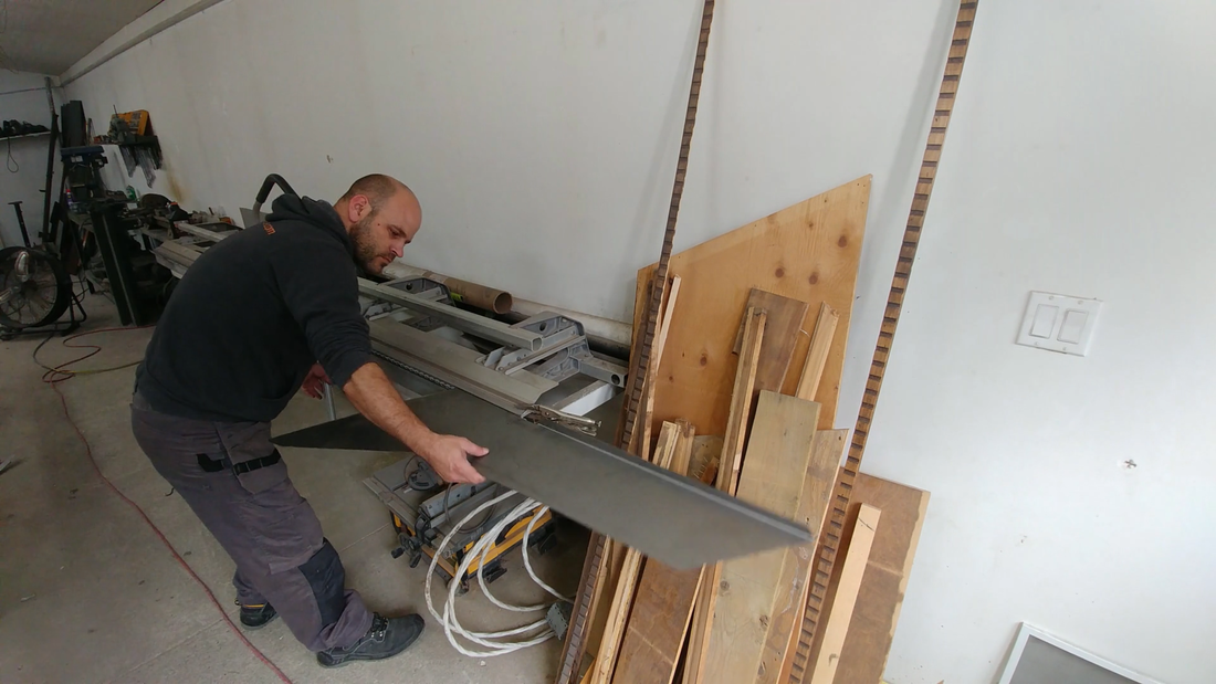
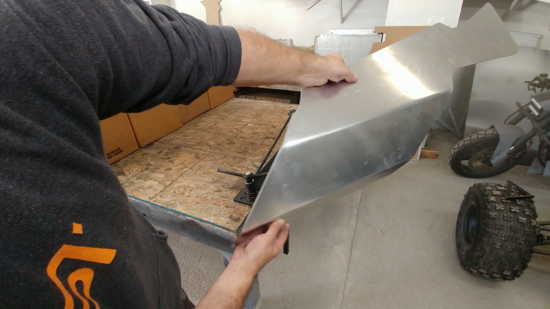
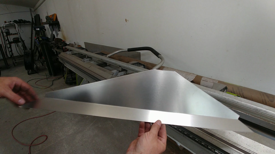
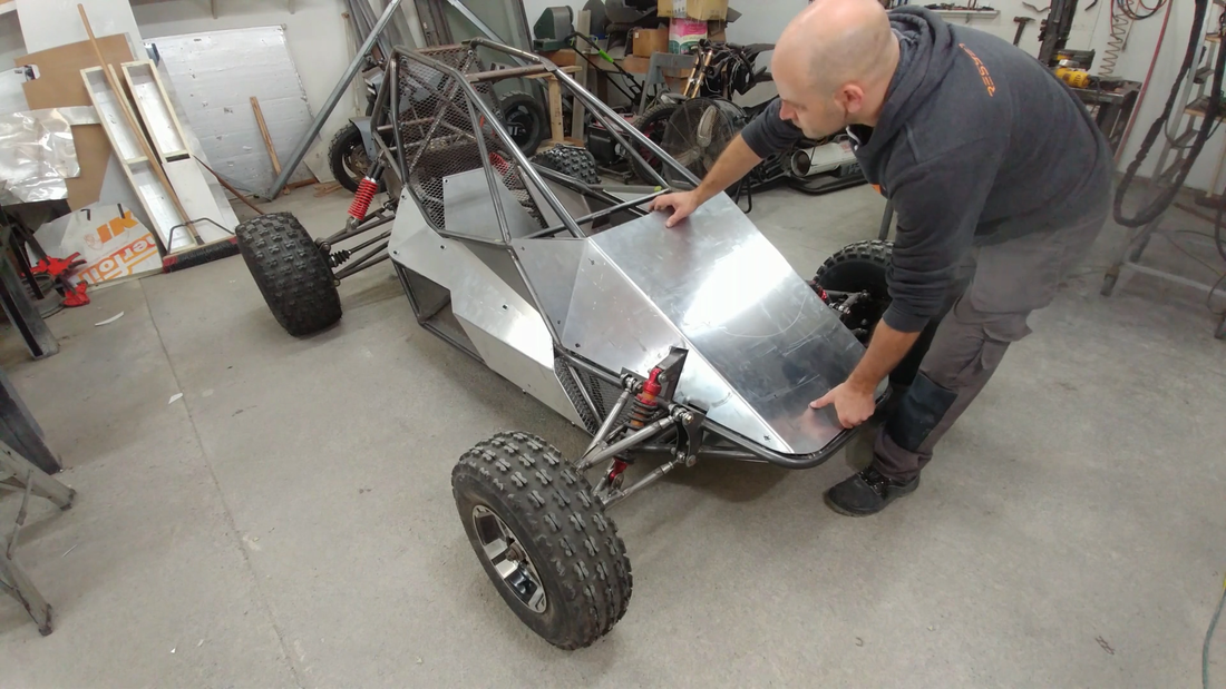
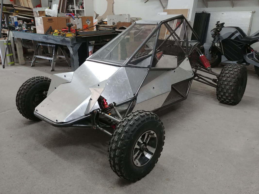
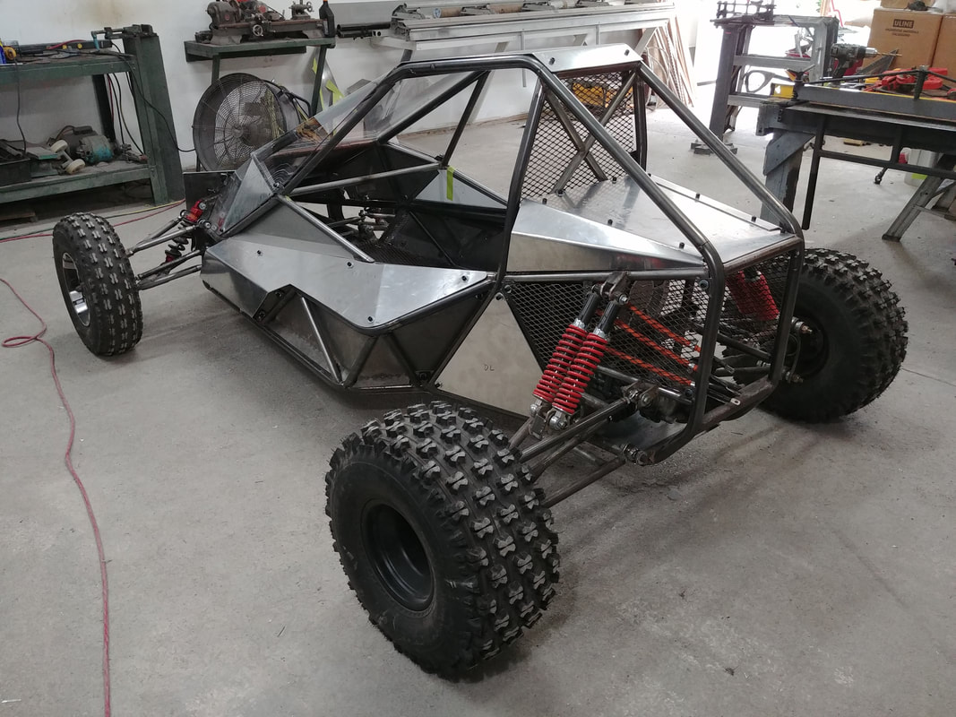
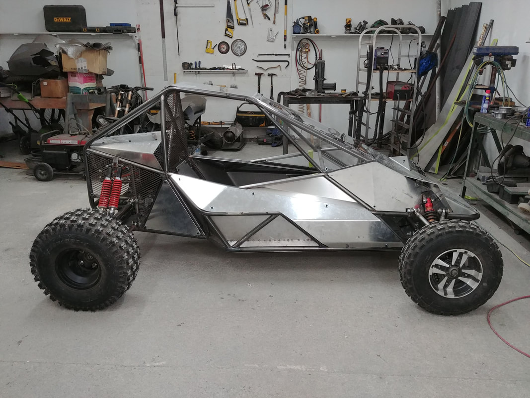
In this video I make the body panels for the electric crosskart. I chose to use 1/8" thick aluminum for most of the job, and also some 20 gauge steel. I originally wanted to use 1/16" aluminum, but the local supply store didn't stock it and it would have been almost twice the cost to order online. I think the 1/8" panels added an extra 25-30 lbs, but they're strong. I'm glad I used it. I should note that using all metal panels effectively turned the cabin into a giant drum, so I intend to make anti-vibration washers from 1/4" silicone rubber to install between all of the bolt-on panels during final assembly to help minimize the noise on the trail. The CAD pics below show what the crosskart will ultimately look like when it's finished.
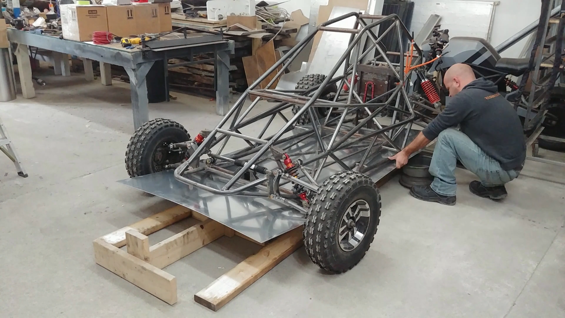
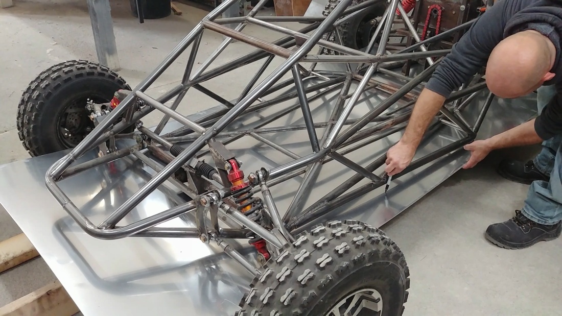
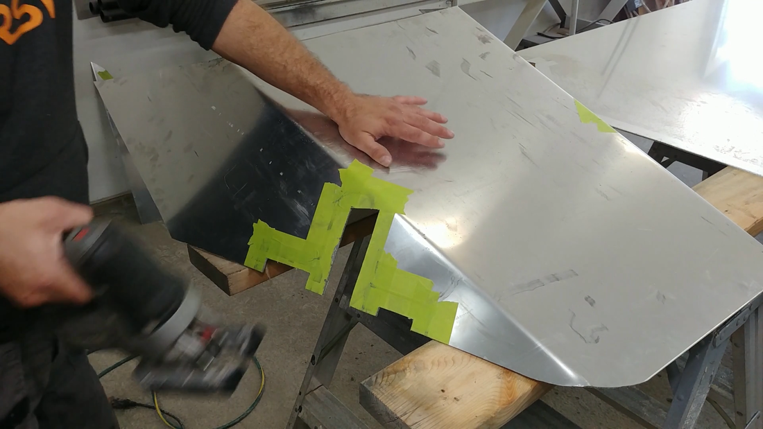
Because aluminum sheet is relatively expensive, I wanted to limit waste as much as possible, so I started with the larger panels first and finished with the smaller panels that I could cut out of the waste left over. The first panel that I made was the skid plate under the chassis. This crosskart is technically an off road buggy so there needs to be some protection underneath to deflect rocks, keep the chassis crossmembers from getting hung up on something in the trail, and keep me protected too. But it's not a rock crawler, so the aluminum should be strong enough for the job.
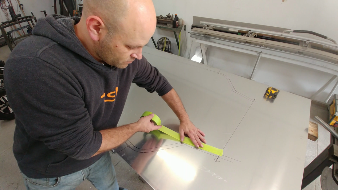
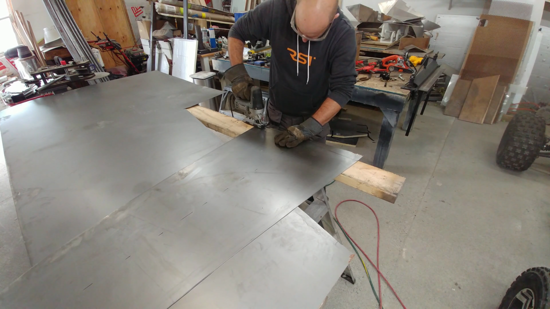
To get the profile of the chassis bottom, I wedged and clamped the aluminum sheet to the chassis and traced the perimeter with a marker. I then taped over the mark and on either side of it with masking tape before cutting it with a jigsaw. This helps keep the aluminum from getting scratched up by the shavings getting caught under the jigsaw base. The adhesive on the tape also keeps the blade lubricated when it heats up and prevents the aluminum from sticking to the blade. Steel is relatively easy to cut with a jigsaw, but aluminum is so soft that it gums up on the blade until it jams up and becomes impossible to cut. Some people like to use cutting oil or WD40 to keep the blade lubricated, which works fine but makes a mess. Lapping the masking tape over the line a little bit works just as good at lubricating the blade, and there's no mess to wipe up after.
To get the profile of the chassis bottom, I wedged and clamped the aluminum sheet to the chassis and traced the perimeter with a marker. I then taped over the mark and on either side of it with masking tape before cutting it with a jigsaw. This helps keep the aluminum from getting scratched up by the shavings getting caught under the jigsaw base. The adhesive on the tape also keeps the blade lubricated when it heats up and prevents the aluminum from sticking to the blade. Steel is relatively easy to cut with a jigsaw, but aluminum is so soft that it gums up on the blade until it jams up and becomes impossible to cut. Some people like to use cutting oil or WD40 to keep the blade lubricated, which works fine but makes a mess. Lapping the masking tape over the line a little bit works just as good at lubricating the blade, and there's no mess to wipe up after.
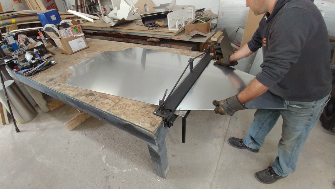
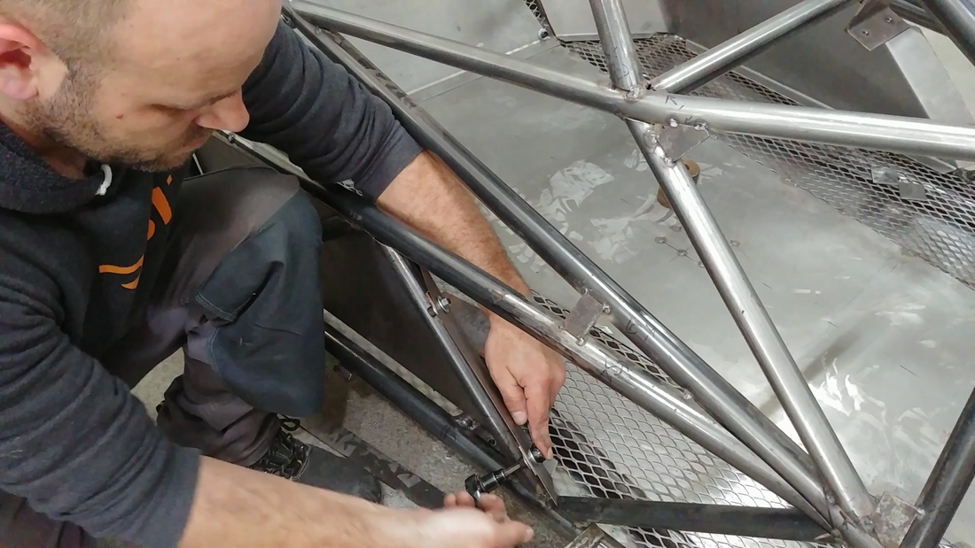
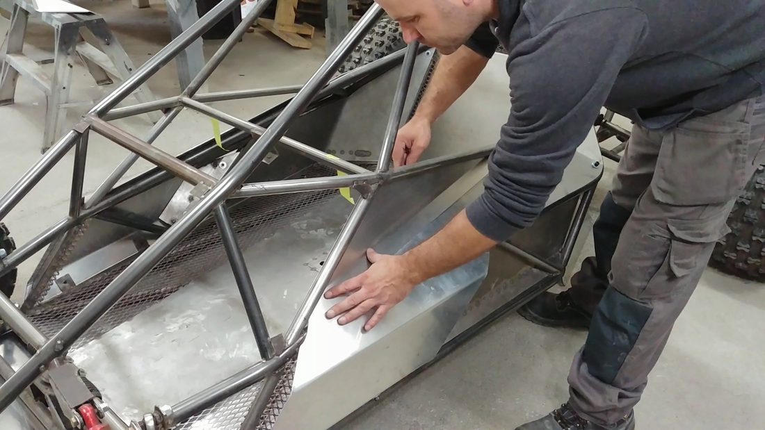
After the skid plate was cut, I sanded and filed the edges to remove the burrs, then clamped it in my new sheet metal brake that I built a few weeks ago, and bent the front end of the plate to match the angle on the front of the crosskart. Then I clamped the plate to the bottom of the chassis again to check the cut and bend, and fastened it to the mounting brackets using 5/16"x1" socket cap screws and lock nuts.
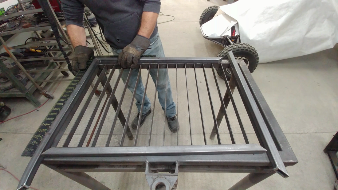
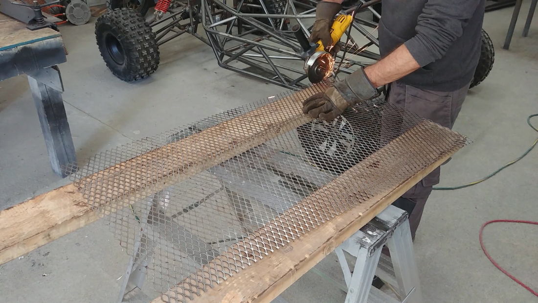
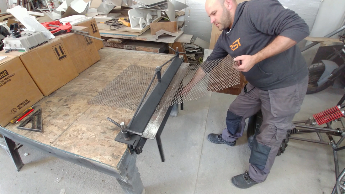
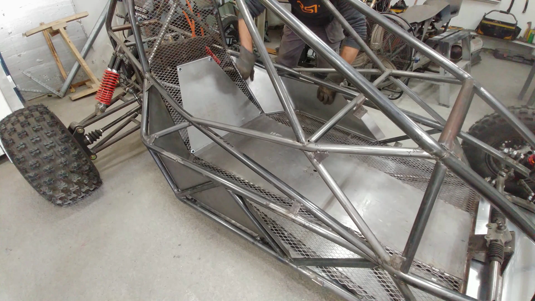
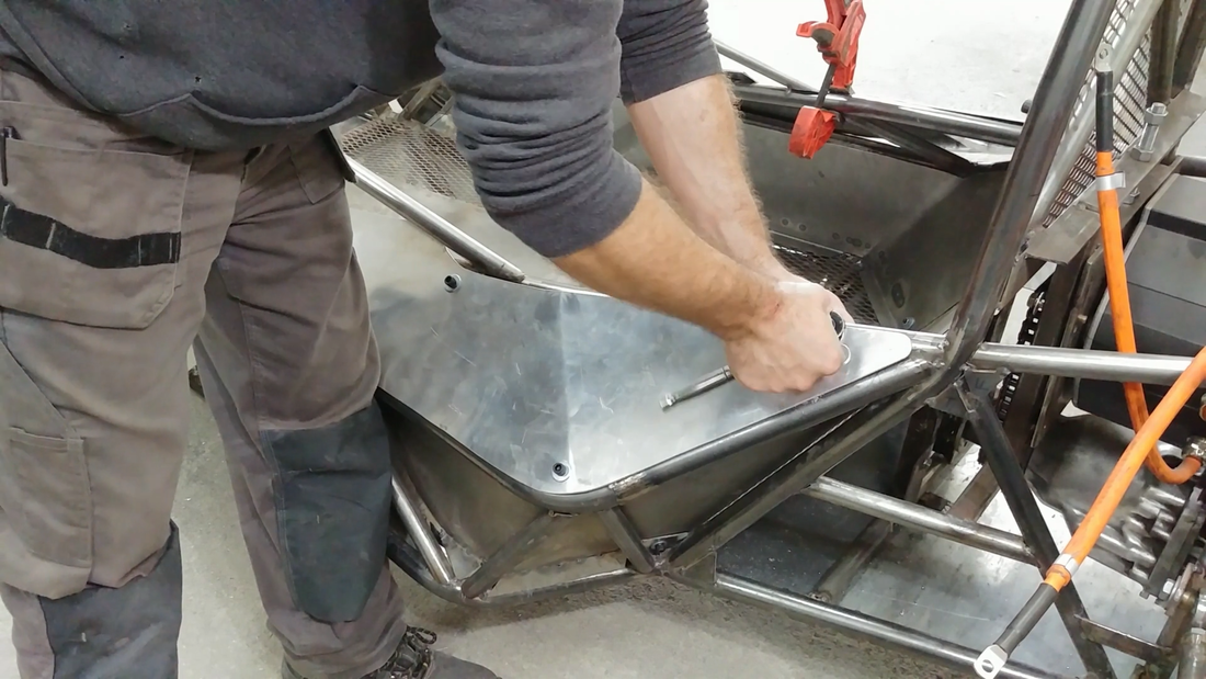
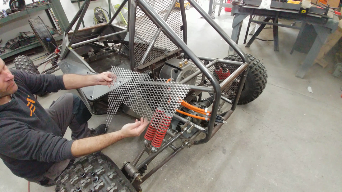
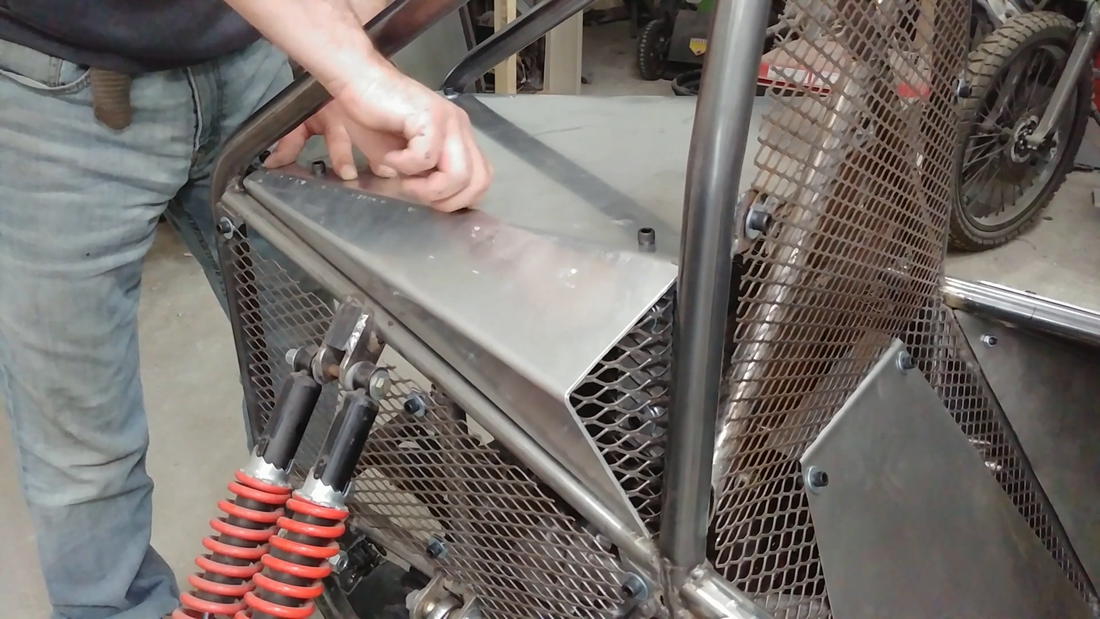
Next, I needed a floor pan of some sort to create a level surface to mount the battery boxes and seat. I didn't want to use the thick aluminum but I didn't want to cover the entire floor in 20 gauge steel, either, because it would have been just as heavy. Instead, I laid out where the battery boxes would be located on either side of the seat, then cut 16 gauge expanded steel sheet to fasten over the area that the batteries will be and used the 20 gauge (solid) steel sheet to cover the rest of the floor under the seat and throttle/brake pedal area. The expanded metal weighs a lot less than than the steel sheet, and it will allow a bit of airflow beneath the batteries to help keep them cool. I welded a 1/8" steel plate between the crossmembers in the seat area to provide a solid structure to bolt the seats to, before welding the rest of the floor in place. I also drilled/cut holes in the floor pan where I needed access to the skid plate bolts.
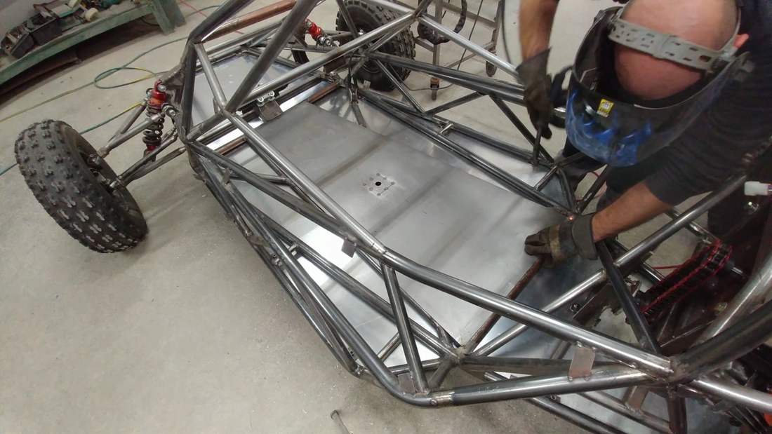
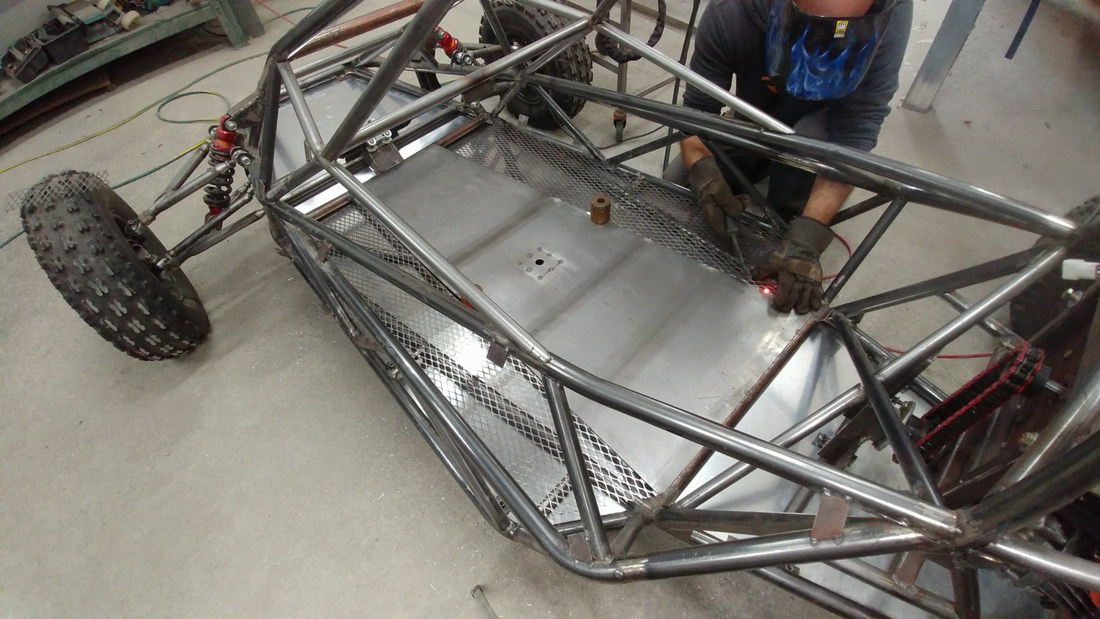
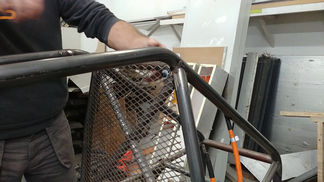
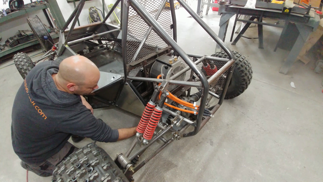
Once the floor was finished, I cut and bent a piece of expanded metal to fasten to the chassis behind the seat. This, combined with the steel plate guard, will offer some protection against the chain and the rest of the drivetrain when I'm driving, but also allow some airflow through to the back of the crosskart where the motor and controller are located. The motor will be liquid cooled by a 12V pump and radiator mounted at the back end of the chassis, but the controller is air cooled so the more airflow I can get back there without exposing it to water, the better.
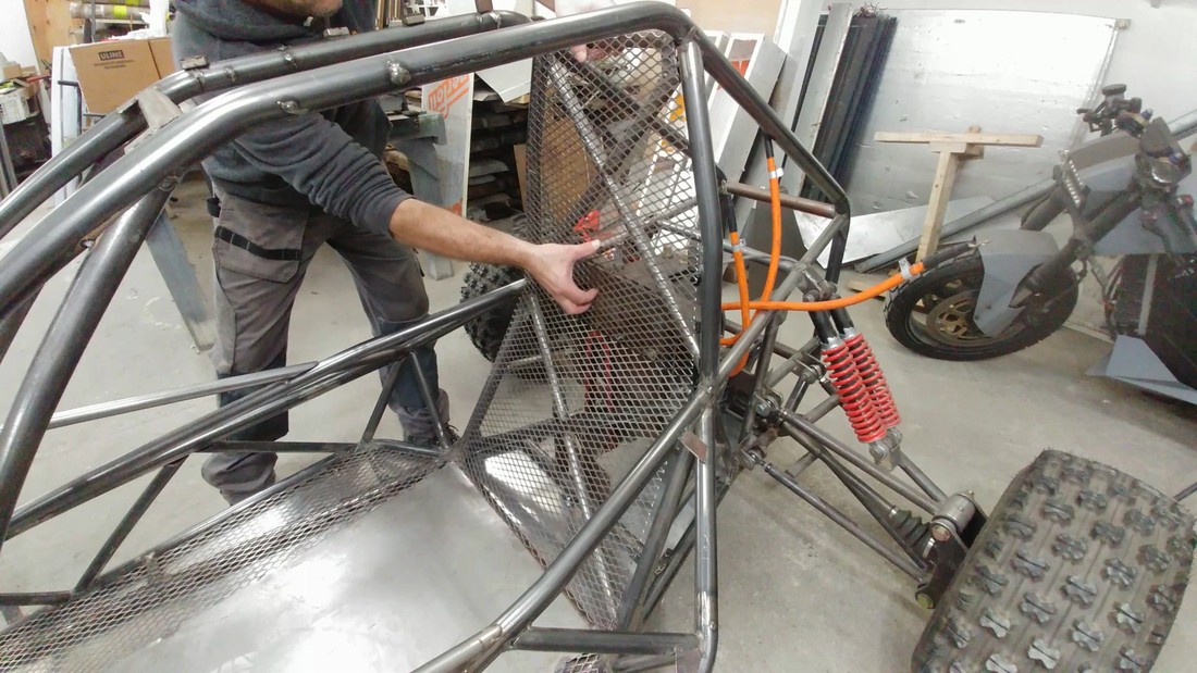
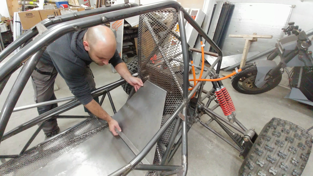
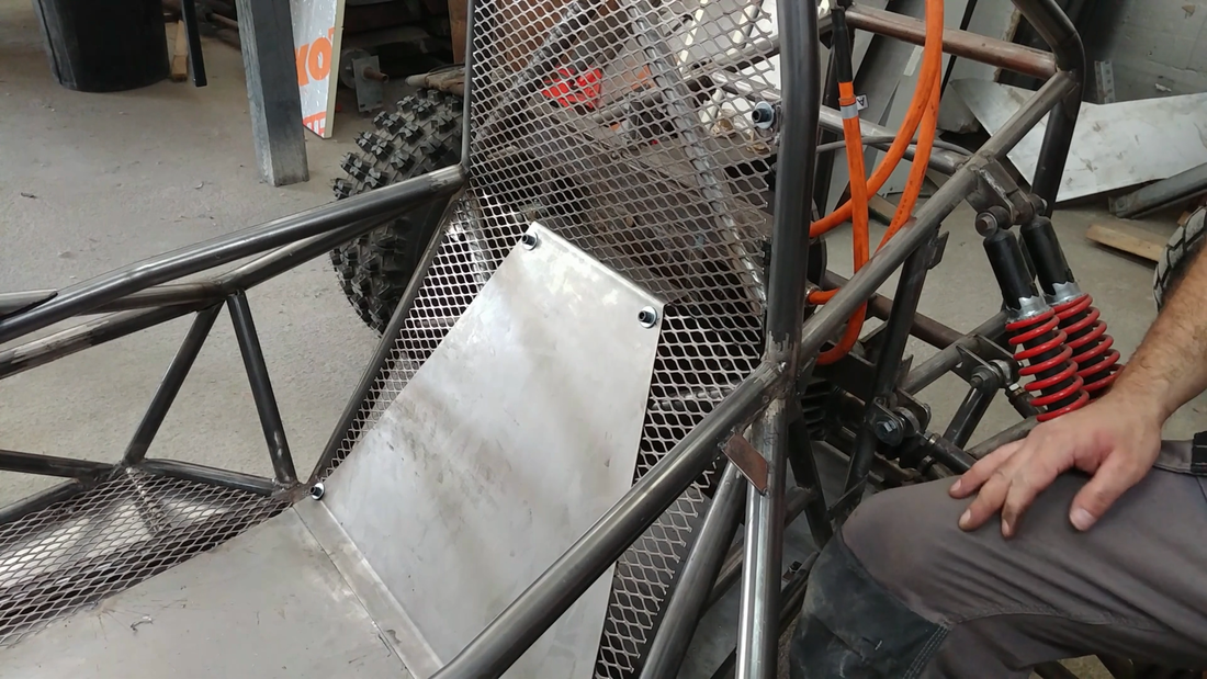
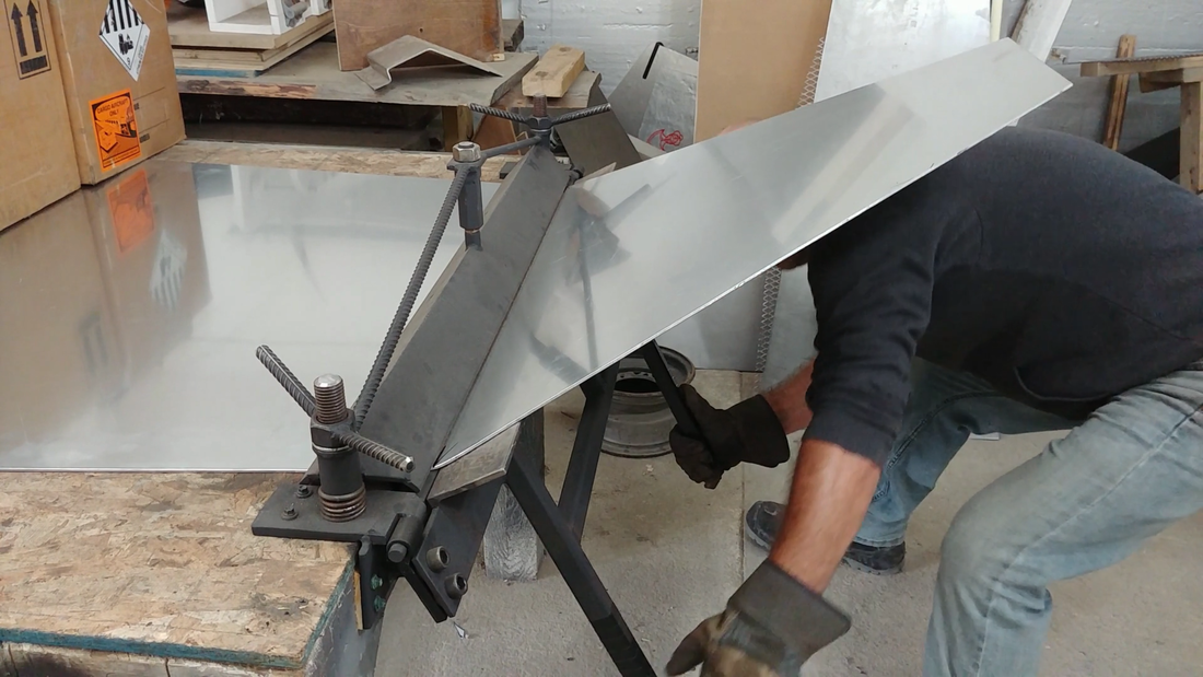
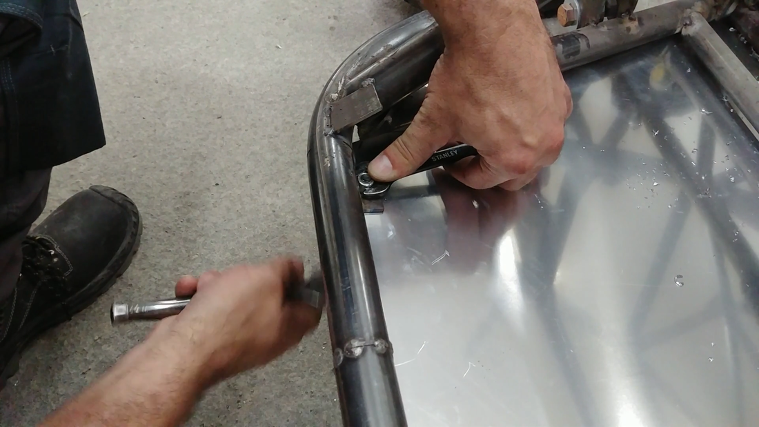
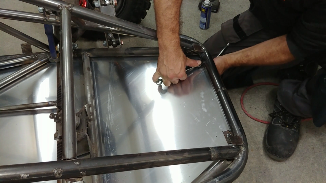
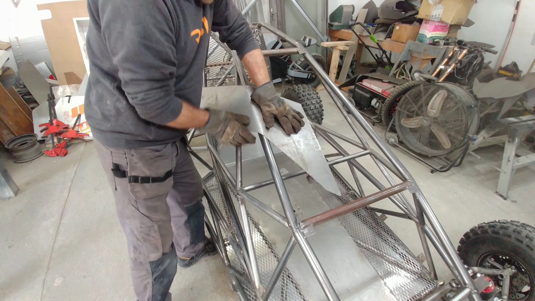
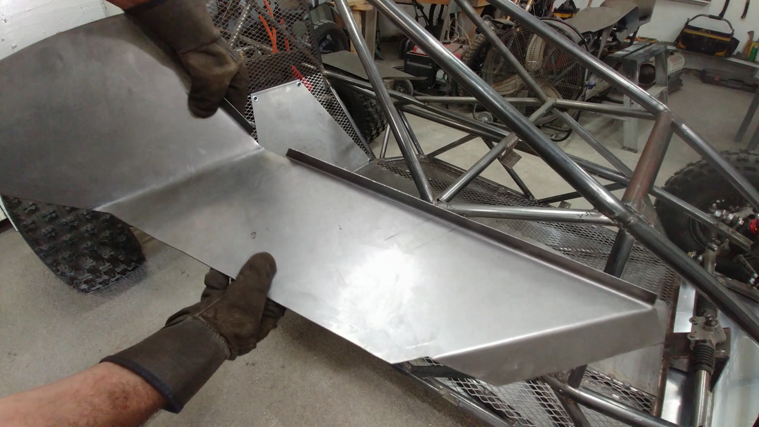
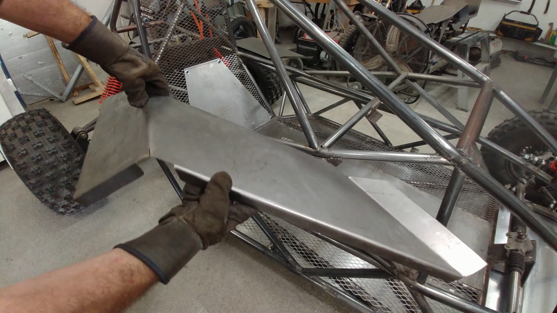
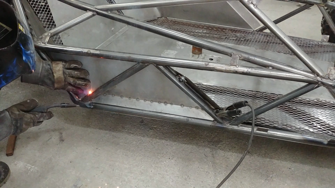
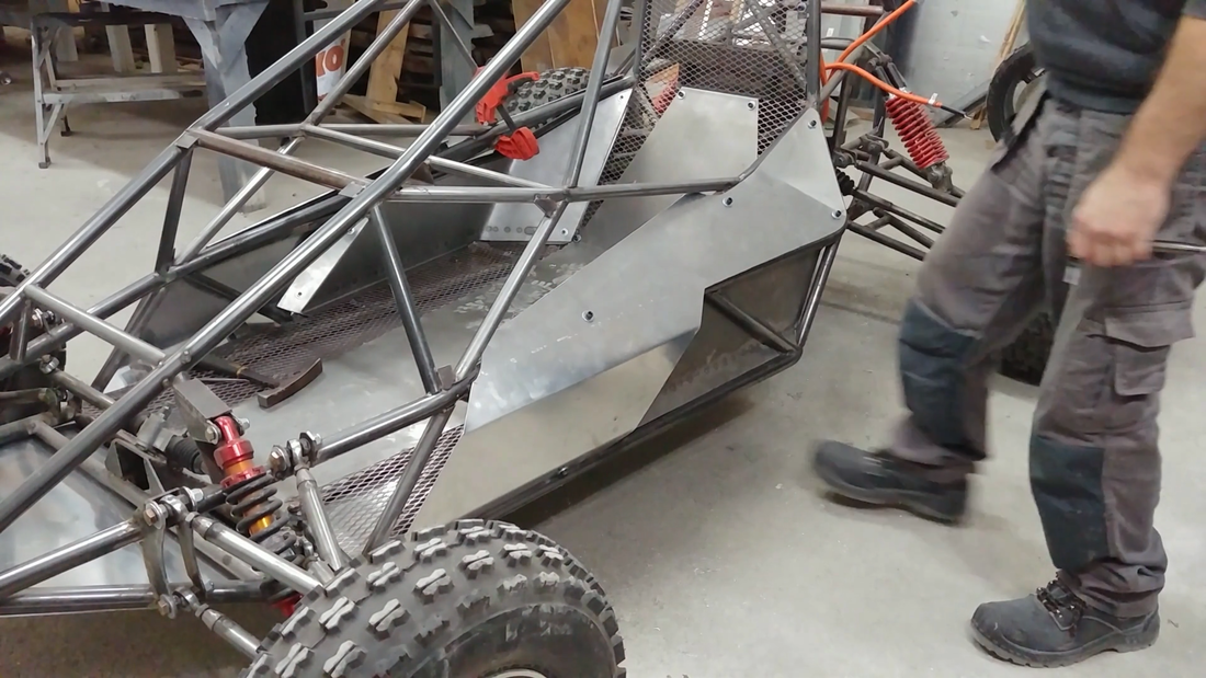
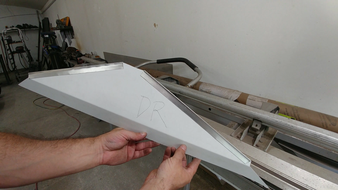
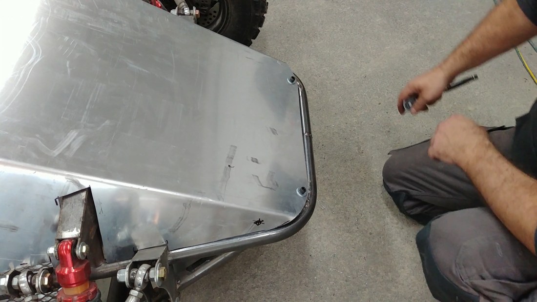
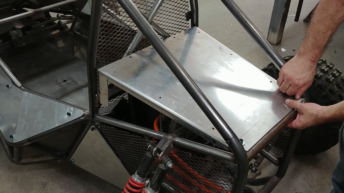
The side panels were made in separate sections. The first were made from steel sheet and formed to fit inside the cabin (at the back half), so that the tubing is exposed on the outside but the panels still protect me and the battery from rocks kicked up by the tires. I did this because I like the look of the tubing and didn't want to cover all of it. I added some angled pieces near the bottom edge to help keep dirt from collecting on the bottom tubes. These were welded to the side panels only, and the panels were bolted to the chassis so they can be removed if/when needed.
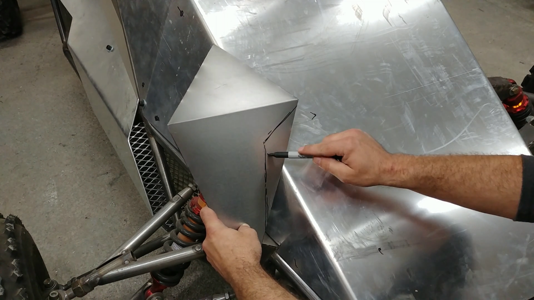
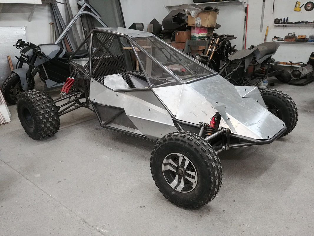
The other panels were made from aluminum sheet and formed to fit on the outside of the chassis, with an air intake port bent into the profile as well. This intake will force air behind the battery boxes to help keep them cool. The air will exit through the expanded metal behind the seat. The intake ports were also fitted with expanded metal at the openings to help keep debris from entering the cabin. A polyester filter material will be used behind the expanded metal to keep out the dust.
The other panels were made from aluminum sheet and formed to fit on the outside of the chassis, with an air intake port bent into the profile as well. This intake will force air behind the battery boxes to help keep them cool. The air will exit through the expanded metal behind the seat. The intake ports were also fitted with expanded metal at the openings to help keep debris from entering the cabin. A polyester filter material will be used behind the expanded metal to keep out the dust.
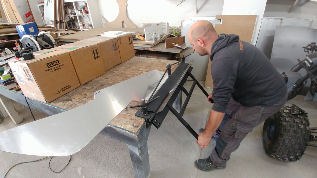
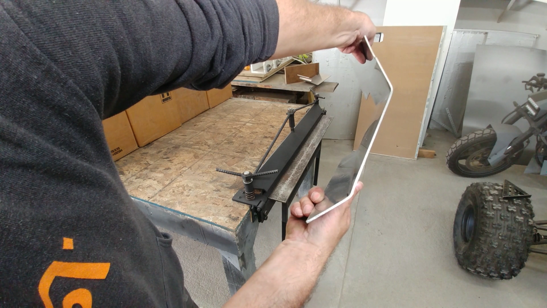
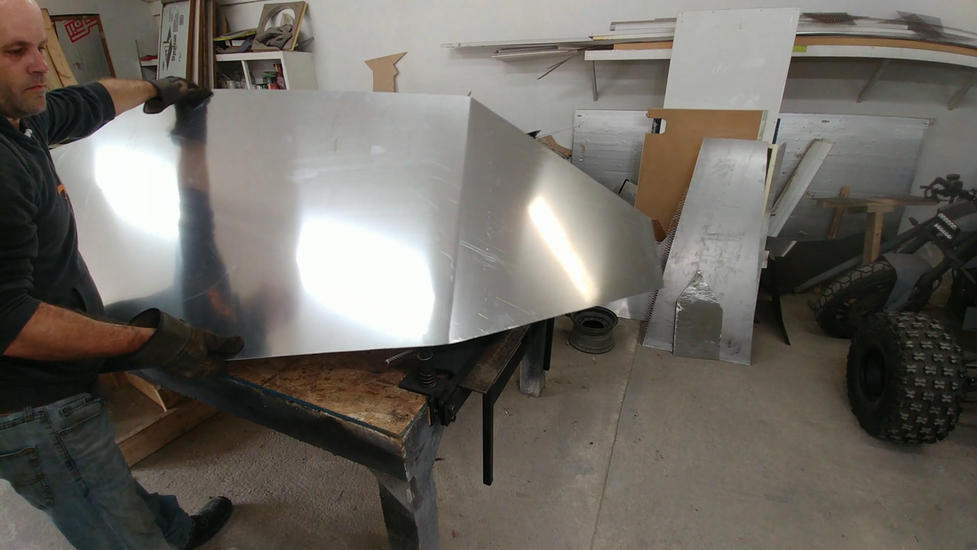
I bent two more smaller aluminum panels to finish the sides just under the windshield. These were made with thin aluminum sheet to save weight since they're just there to help block the wind. Then I bent the hood and notched the edges around the suspension mounting brackets, and bolted it to the chassis. I should note that I made templates with aluminum flashing for marking and cutting all of the complicated panels. Cardboard would have been cheaper, but I had none in the workshop and the aluminum templates will last longer anyway, in case I damage something later in the future and need to make a replacement panel.
I also bent two fenders to mount to the hood over the front suspension to help streamline that area and keep water out.
I also bent two fenders to mount to the hood over the front suspension to help streamline that area and keep water out.
I then moved on to closing in the back of the chassis will more aluminum and expanded metal to protect the chain, motor & controller wiring, radiator, etc. I installed an aluminum cargo bed as well. It's not much but it can fit a backpack and a small cooler. Good enough for a day on the trail. It also doubles as a heat sink, since the controller will be mounted to it underneath to keep it out of the rain, too. I thought the controller was sealed and IP67 rated when I bought it, but I misread the specs. It's IP54 rated, so it can take some splashing from the tires or a garden hose, but it can't be submerged. Mounted high under the cargo bed next to the motor is a good place to keep it dry and cool and minimize the transmission wires. On each side of the cargo bed, I installed more forced air intake ports to help drive air by the controller - polyester filter material will be used here, as well.
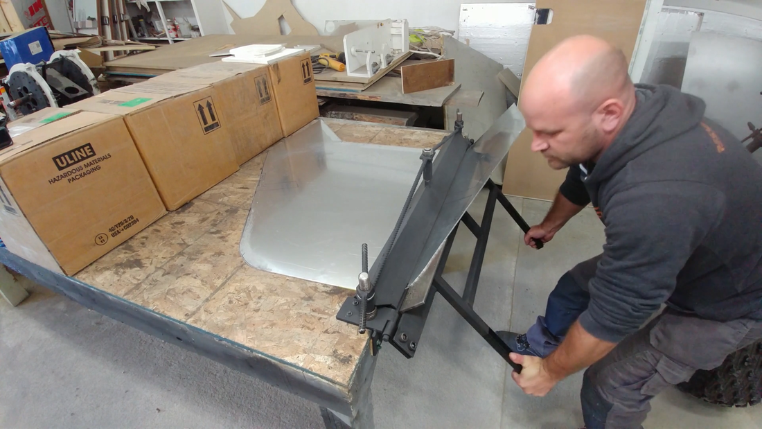
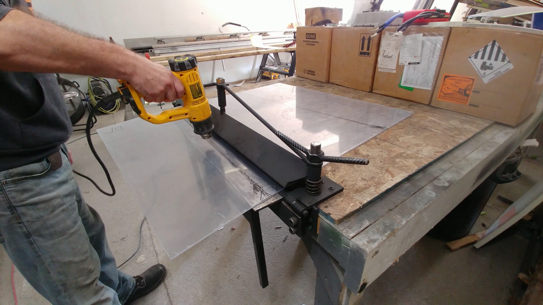
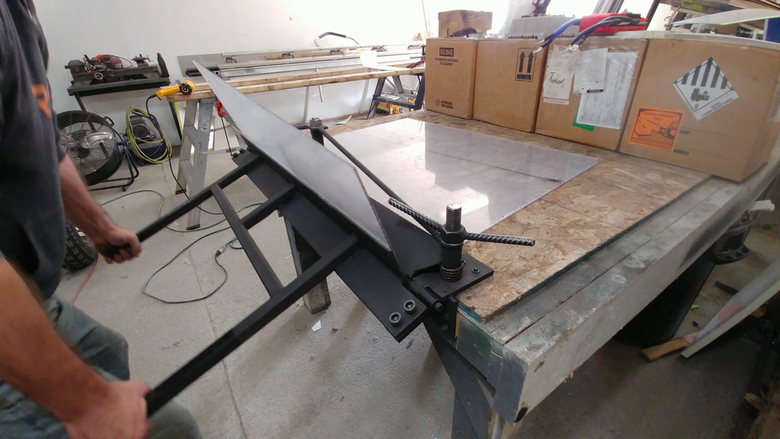
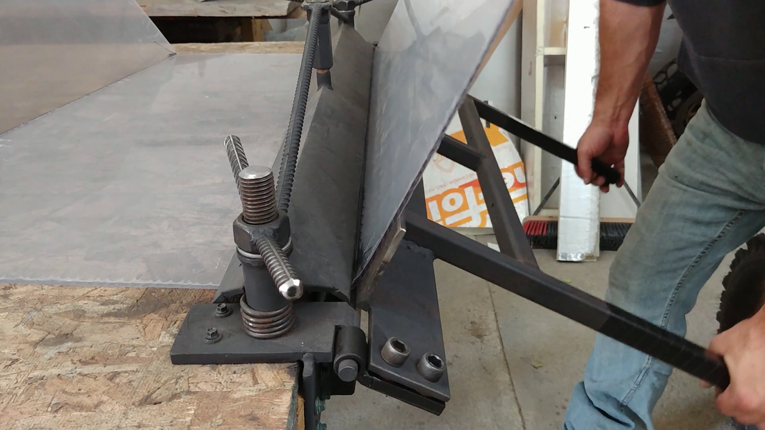
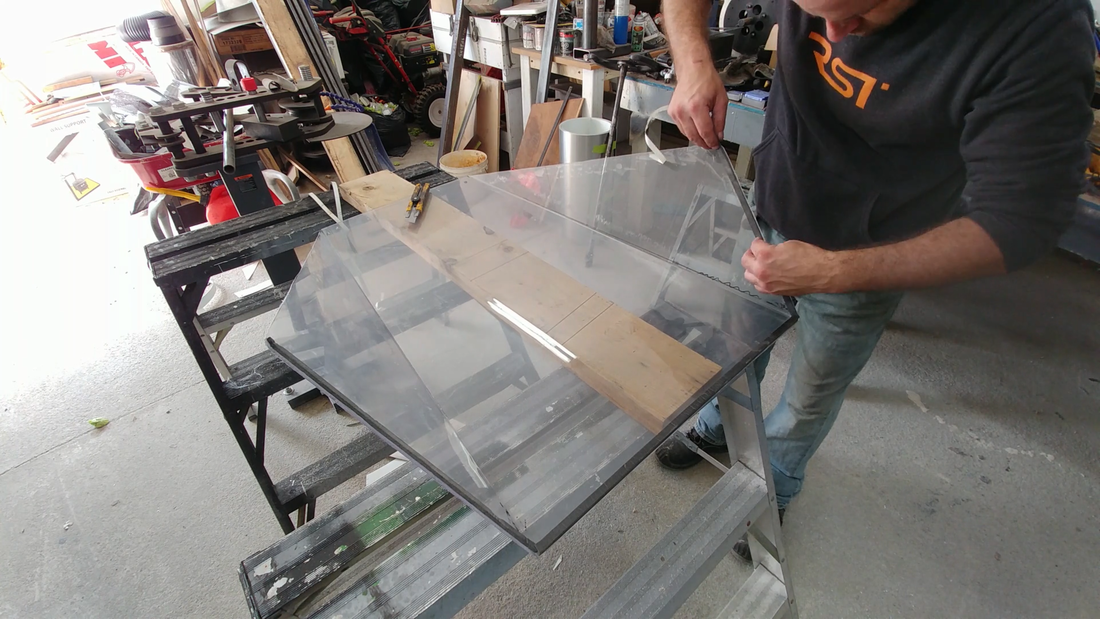
Next, I laid a sheet of 1/8" thick UV stabilized polycarbonate onto the chassis where the windshield will be located, and marked out the main tubes and hood so that I knew where to cut and bend the plastic for a tight fit. Once I had it marked out, I set it up in my sheet metal brake for the first bend. Before bending, I heated the polycarb along the bend line with a heat gun until it was more flexible (but not too soft), then clamped the piece and bent it. There's a fair amount of springback when bending polycarbonate, so I had to overbend quite a bit to get the angle that I needed. But it worked out fine. Once the angle was established, it held its form when the plastic cooled. I should have put tape over the brake clamp edges though, as they made a few scratches in the plastic.
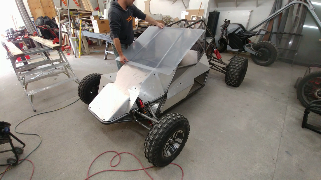
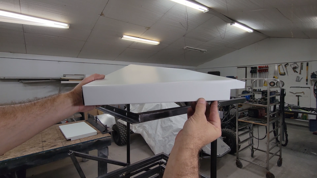
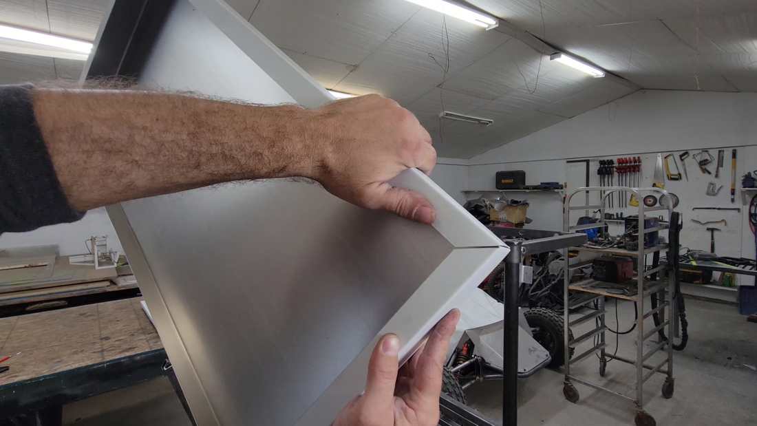
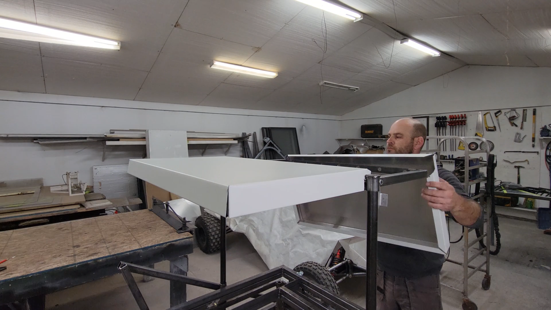
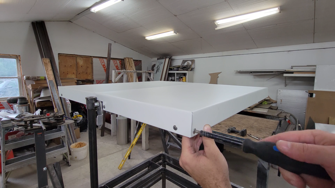
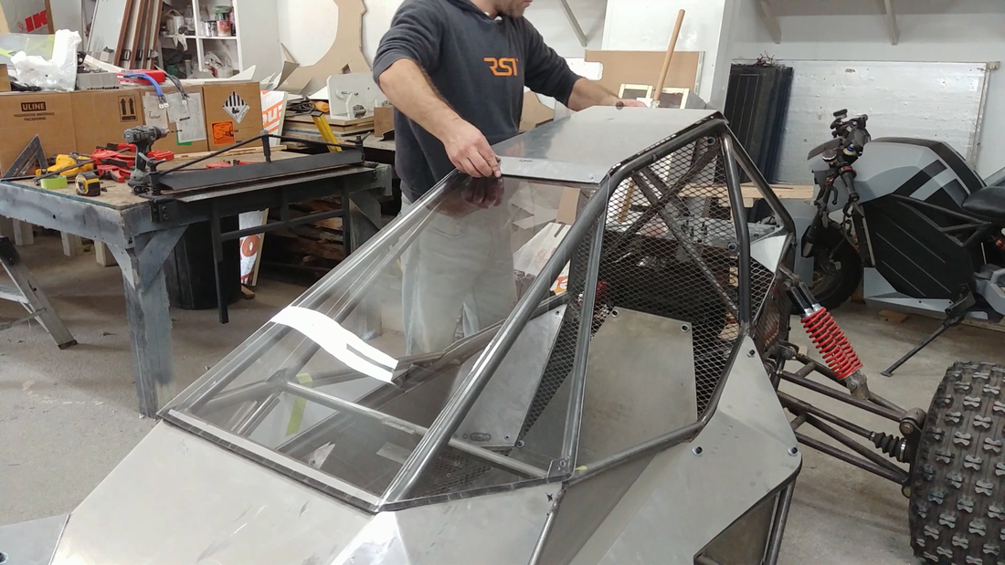
After adding some 1/4"x1/2" weatherstripping foam to the bottom inside edge of the windshield, all I had left to do then was bend the aluminum plate for the top of the chassis and then install it with the windshield. They're arranged so that the windshield overlaps the hood, and the top aluminum plate overlaps the windshield, so that they're all shedding water properly if I get caught in the rain or hit a big water hole in the trail. The BMS is going to be located under the dash, just behind the hood, so my main concern is keeping that area absolutely dry. The battery boxes will be made waterproof, so there's no worry in that regard. Speaking of which, building and fitting the battery will be the next task starting tomorrow. I'm not going to wire anything up yet, I just want to fit the cell packs in the cabin to make sure everything fits properly and I don't have to make any modifications before it's all painted. I'll have another video covering that in a couple of weeks. Make sure you've subscribed on Youtube and click the notification bell so you don't miss it.
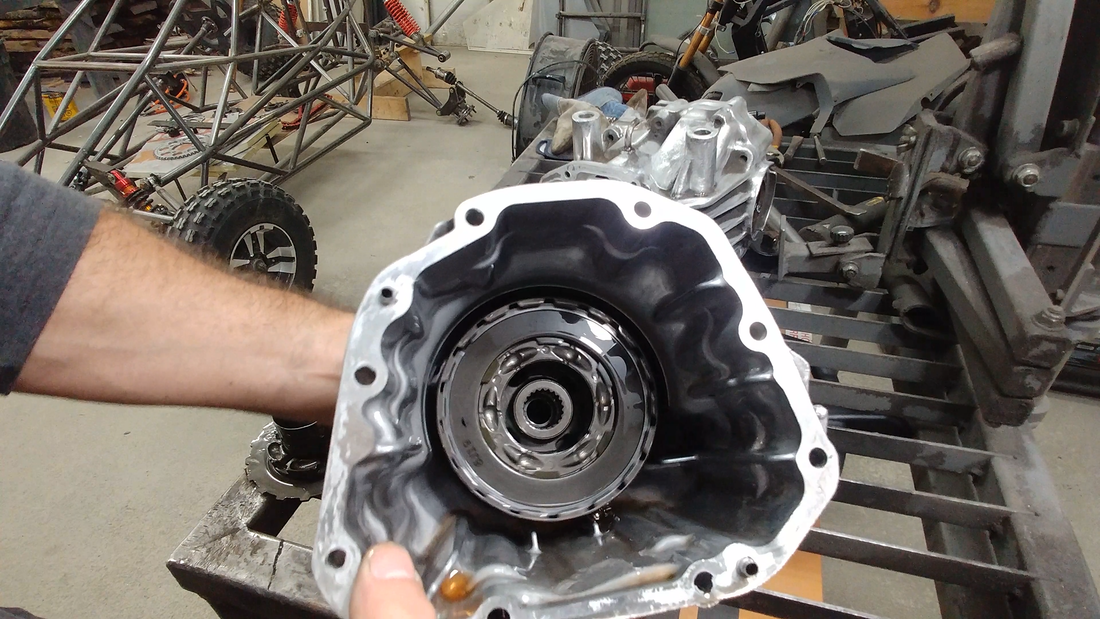
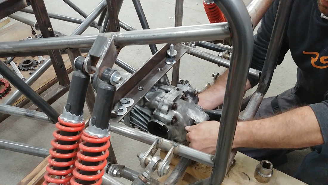
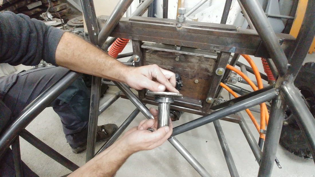
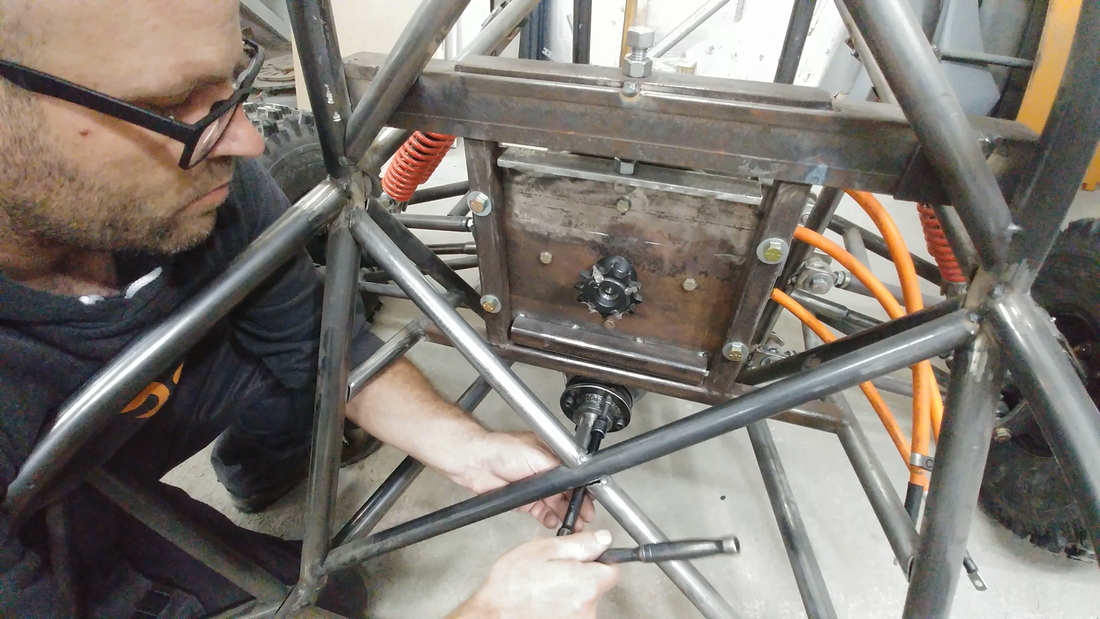
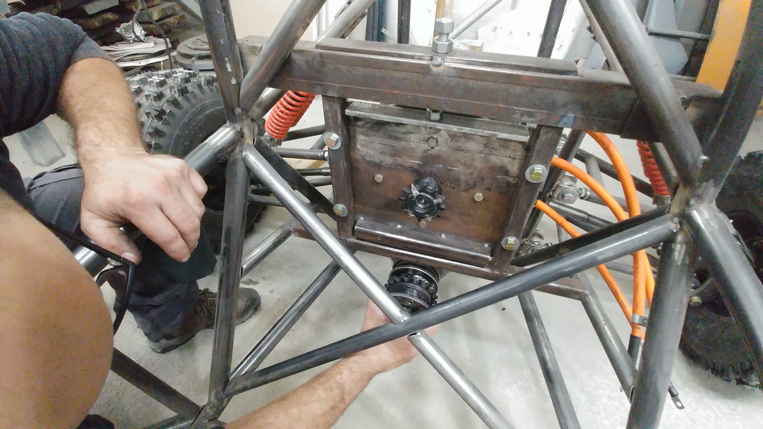
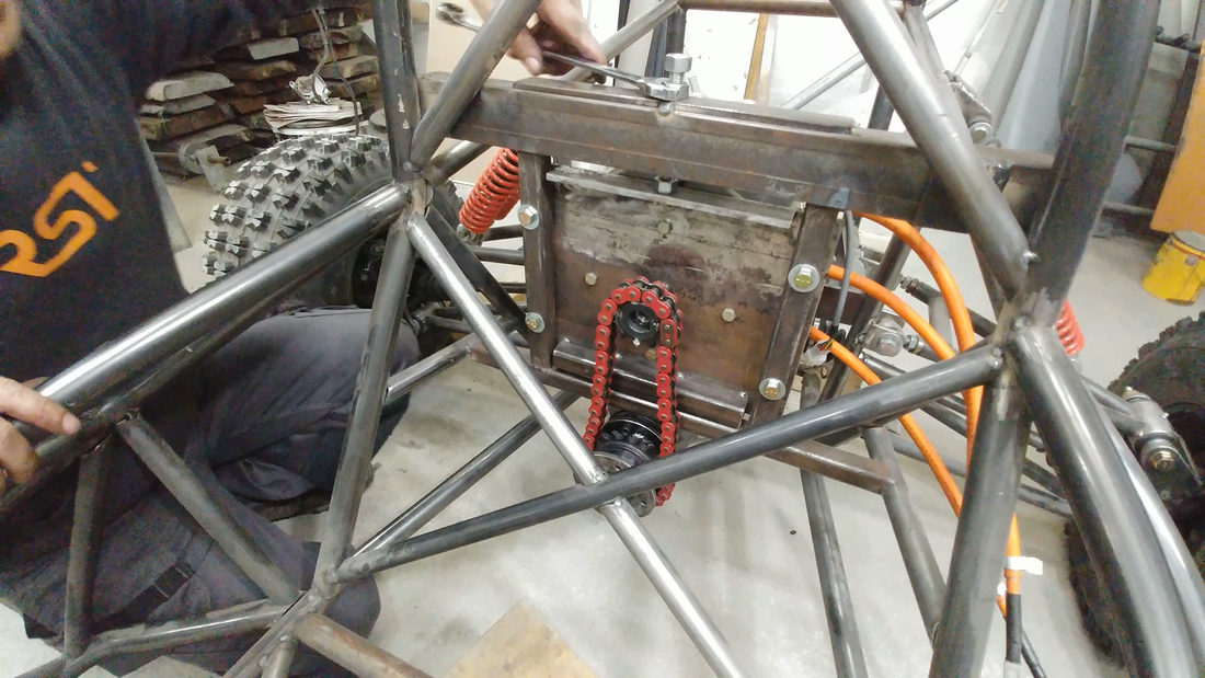
In this video I fit the drivetrain to the electric crosskart chassis. I'm using a rear open differential from a 2007 Honda AWD CR-V to transmit power from the motor to the rear axles. It's light and compact, and will eliminate any understeering that would otherwise happen with a solid axle. But a couple of mod's need to be done to make it more suitable for the crosskart. For ex, a limited slip diff would be ideal; when one wheel spins, the LSD would automatically lock up the other wheel so both have traction. A cheap LSD conversion kit is available for this differential and will be installed before the final assembly (after paint).
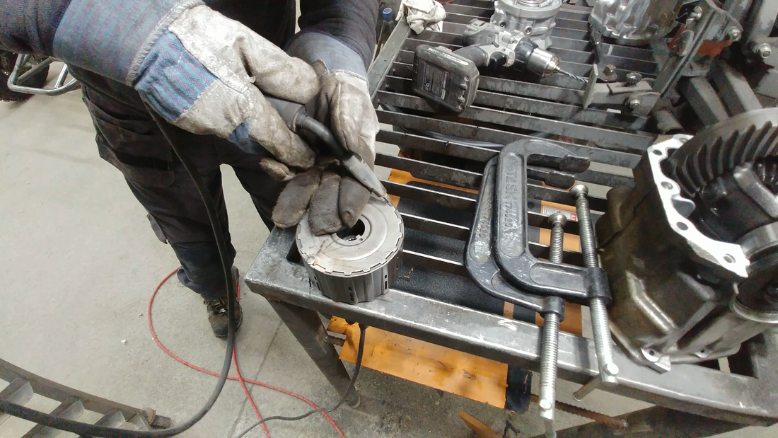
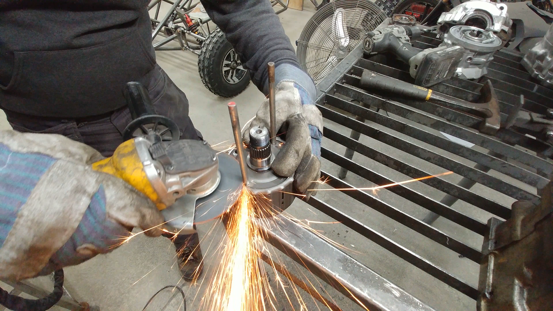
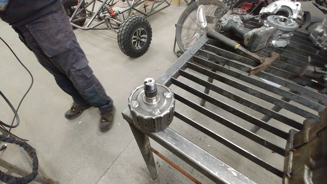
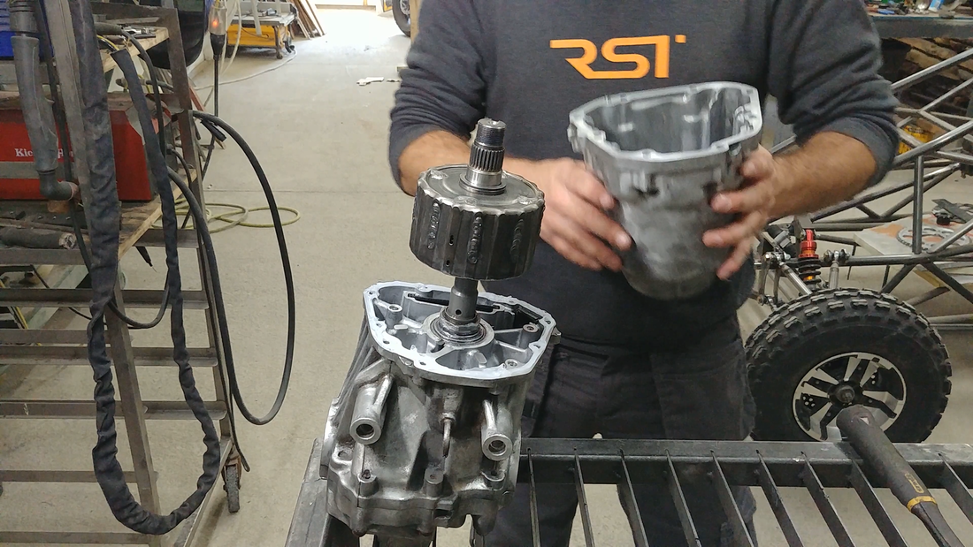
Another mod that must happen is pinning the clutch pack located in the front of the diff. Being an AWD, the input shaft from the rear diff rotates freely inside the clutch pack in normal conditions. When the front wheels slip, the pump located behind the clutch pack automatically forces oil into the back of the pack which puts pressure on the clutch plates to lock the clutch pack and diff shaft together and transmit power to the rear wheels.
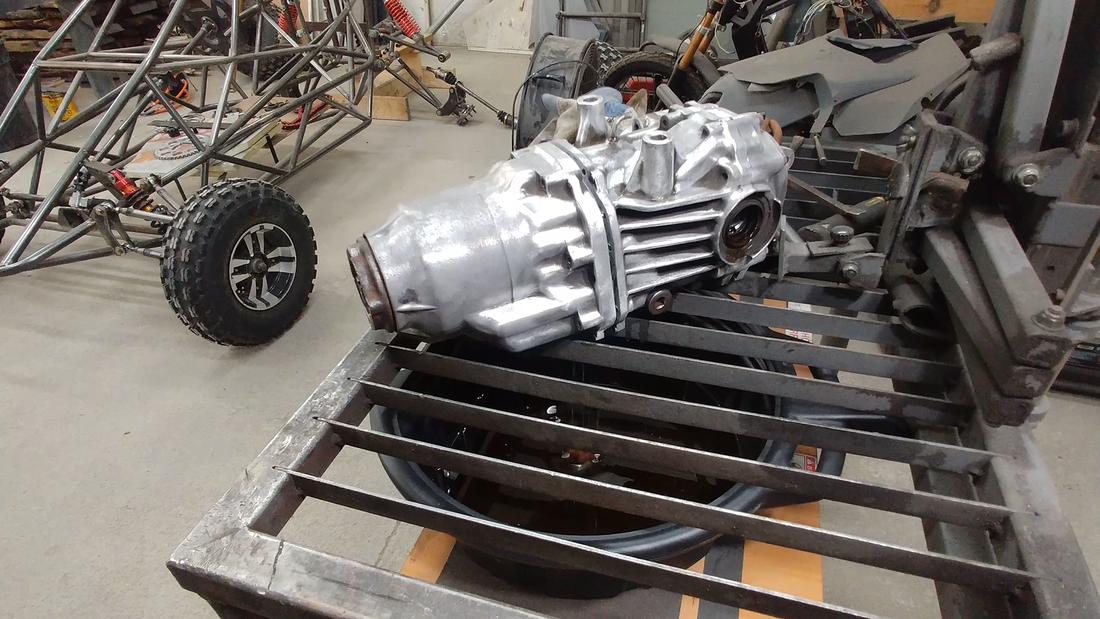
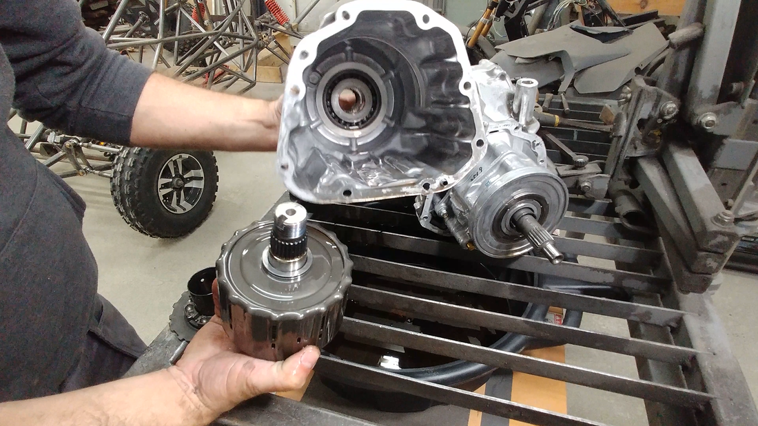
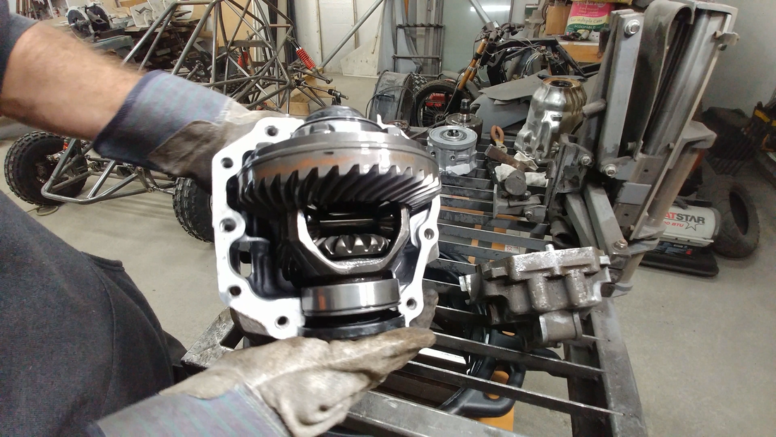
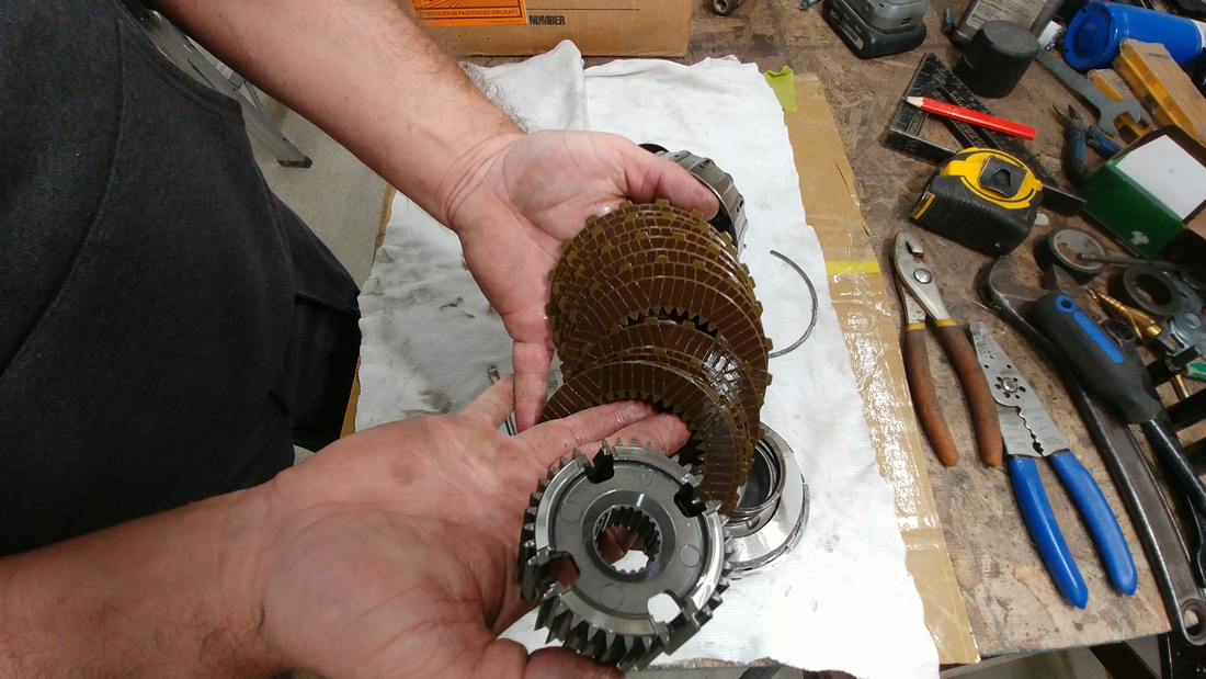
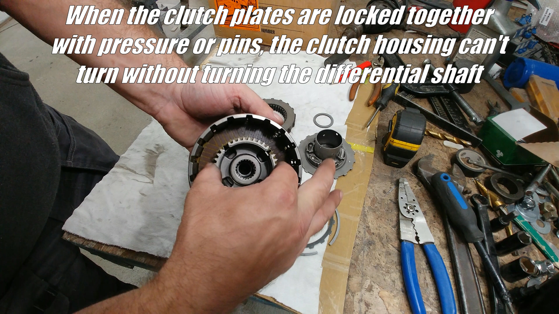
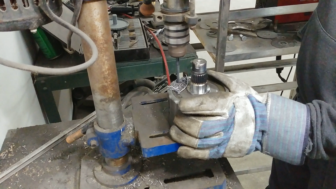
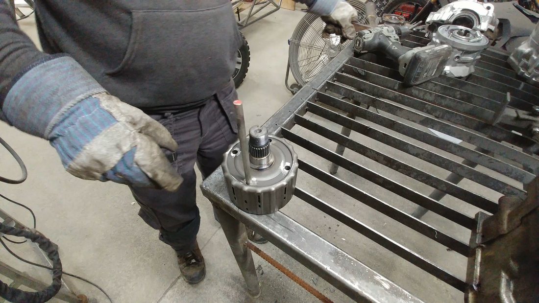
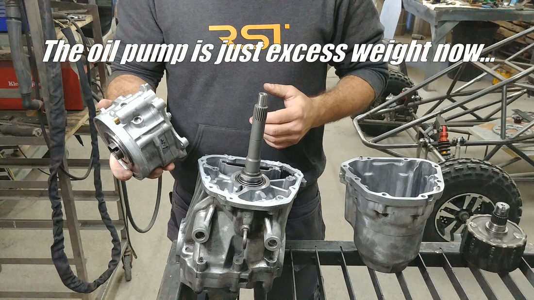
If the differential is installed without dealing with the clutch pack, then it'll cause a slip and lag in response every time I use the throttle. To get around this problem, I drilled and pinned the clutch plates to the clutch housing so that it's permanently locked to the diff's input shaft. The oil pump was removed completely, since the clutch is no longer a clutch and the pump would just be dead weight. I bolted everything back together and fit the differential to the chassis.
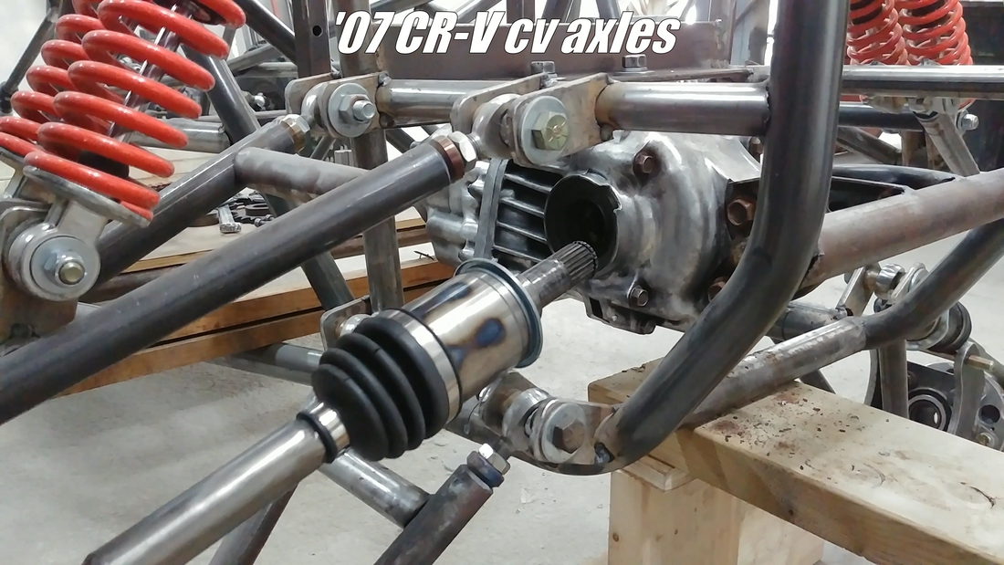
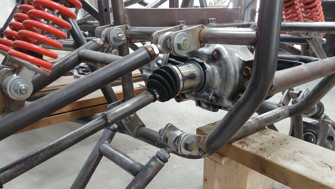
I then installed the cv axles, which were shortened from their original length (to keep the track width at 62" with the offset wheels) by removing the required amount from as close to the inner joint as possible, then grinding the cut ends to a 45° point and welding them back together. Then a 4" long DOM tube sleeve was slipped over the joint and welded. Ideally, you shouldn't do this. A cv axle is technically a torsion bar, ie: a spring. It's intended to flex with the torsional force created when the diff twists the axles to turn the wheels. If the shafts re too brittle, they'll break. This method increases that risk, which is why I didn't show it in the video but I'm curious to see how they hold up. The best way to shorten the shafts is to take them to a local machine shop and have them disassemble the cv joint so they can cut the shaft to length and re-spline the end to fit the joint again. It'll cost, but you won't have to worry about it when you're messing around on a trail in the middle of nowhere.
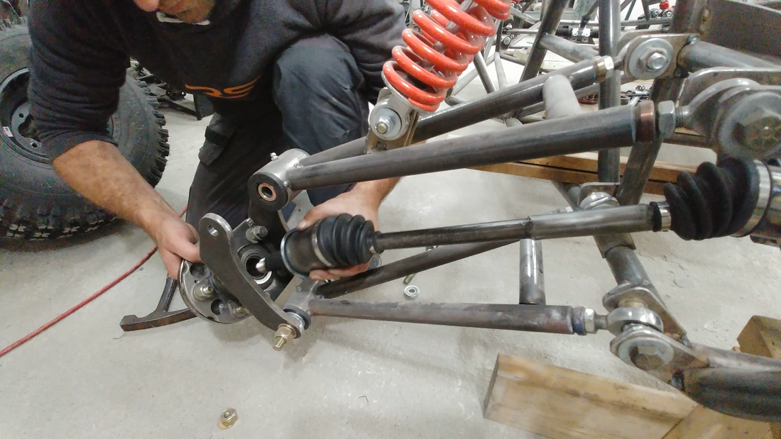
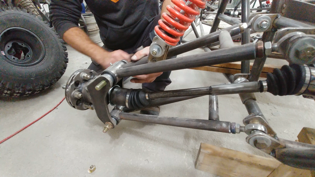
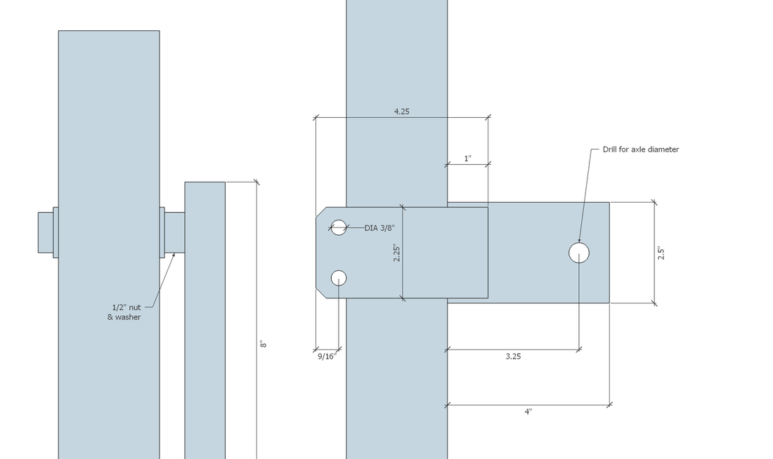
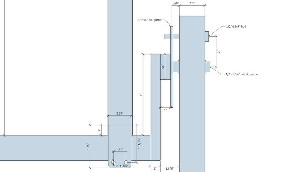
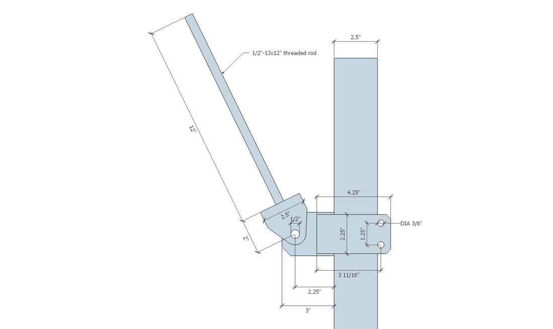
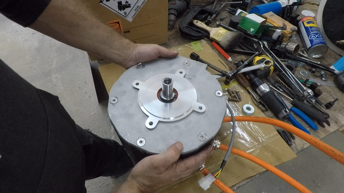
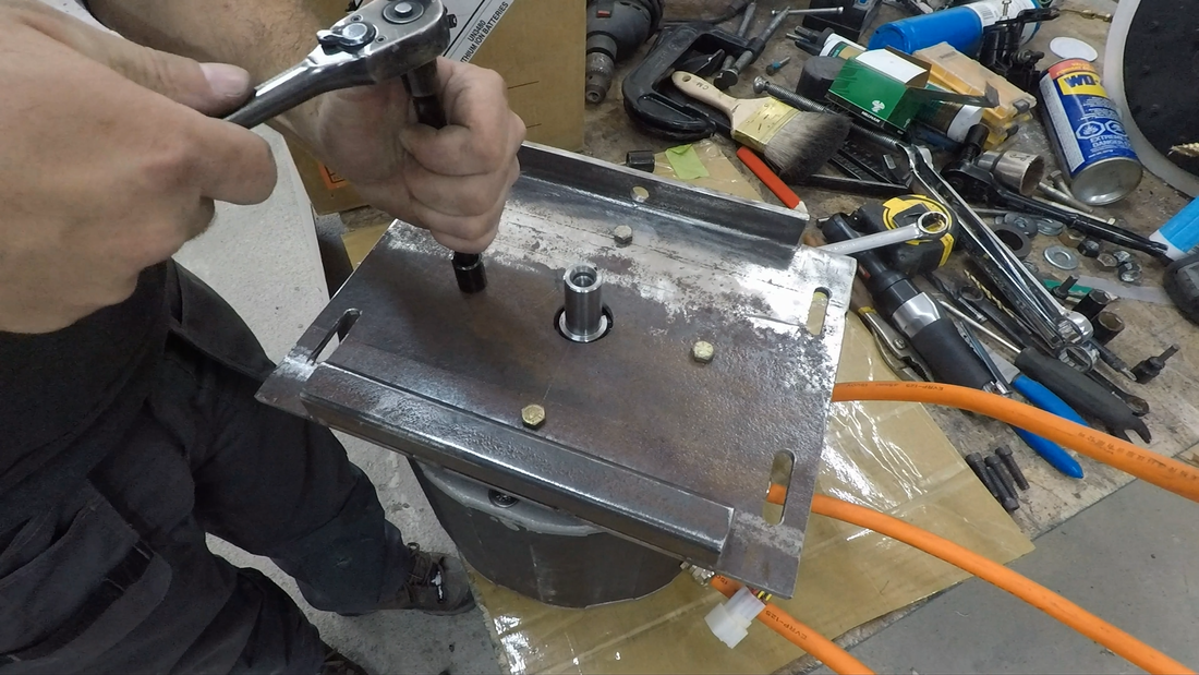
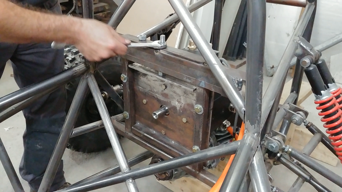
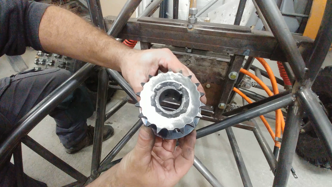
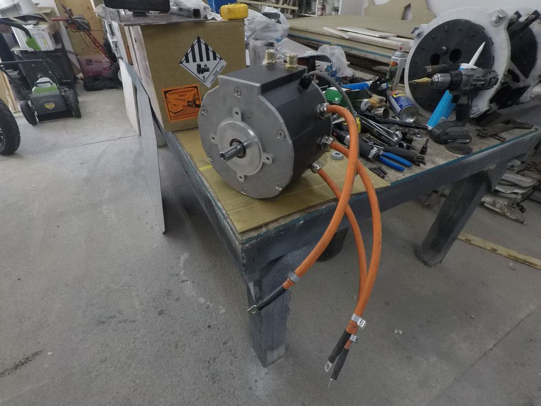
The differential has a 16T drive pinion and a 41T drive gear = a gear ratio of 2.56:1. I'm using a 12T drive sprocket with a 7/8" keyed weld-on hub on the 55 kW ME1616 motor and linking it to a 18T sprocket with a 1-1/4" keyed weld-on hub connected to a keyed stainless steel shaft that I welded another hub and plate to which was bolted to the diff's output shaft. Total sprocket ratio is 3.84:1. The sprockets are driven by a 530 o-ring chain. The motor is mounted to a plate with elongated bolt holes and a piece of 90° angle welded to the top, which a 1/2"-13 threaded rod is fastened to and serves as part of the chain tensioner.
With the 22" wheels and a max motor rpm of 6000 (~1500 at the wheels), the top speed should be around 160 km/h (~100 mph). The motor is capable of 0.33 nm (0.24 ft-lb) of constant torque per amp which amounts to around 82 nm (60 ft-lb) continuous or ~180 nm (132 ft-lb) at peak power at the motor shaft, so the gearing should bump it up to close to 316 nm (233 ft-lb) continuous, 700 nm (500 ft-lb) peak at the wheels.
The rear brakes, again from a Yamaha Banshee, will be mounted in front of the motor instead of the axles, and will consist of one large rotor with two hydraulic calipers, both of which have a spring loaded mechanical parking/emergency brake feature that will be connected to a cable and lever in the cockpit.
The rear brakes, again from a Yamaha Banshee, will be mounted in front of the motor instead of the axles, and will consist of one large rotor with two hydraulic calipers, both of which have a spring loaded mechanical parking/emergency brake feature that will be connected to a cable and lever in the cockpit.
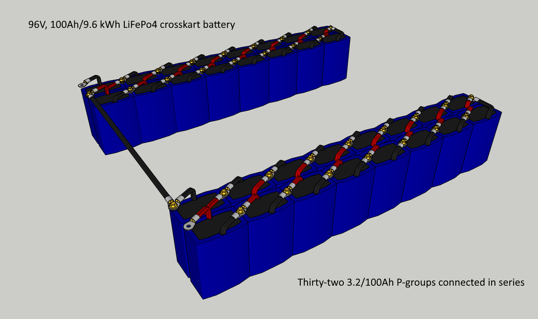
I've decided to make the battery a bit smaller than originally planned, to save some space and weight. Instead of a 24P32S pack of the 5000mAh LiFePo4 cells from batteryhookup.com for 11.5 kWh @ 96V, I'm building a 20P32S pack for 9.6 kWh @ 96V.
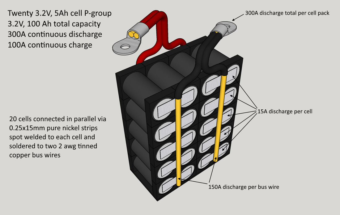
I'll connect 20 of the 3.2V, 5Ah batteryhookup cells in parallel to form a larger 3.2V, 100Ah cell or 'p-group' using 0.25x15mm nickel strips and 2 awg copper bus wire; the nickel strips will be soldered directly to two bus wires on each side of the pack first to avoid overheating the cells, then the strips will be spot welded to each cell. The purpose of the bus wires is to eliminate the need to spot weld 4 or 5 layers of nickel strips for the series connections, which would add more work and force me to make the battery in one or two large and awkward to handle blocks. Instead, I'll be able to install the battery into the crosskart one p-group at a time, and easily connect/disconnect them with a couple of wrenches.
I'll connect 20 of the 3.2V, 5Ah batteryhookup cells in parallel to form a larger 3.2V, 100Ah cell or 'p-group' using 0.25x15mm nickel strips and 2 awg copper bus wire; the nickel strips will be soldered directly to two bus wires on each side of the pack first to avoid overheating the cells, then the strips will be spot welded to each cell. The purpose of the bus wires is to eliminate the need to spot weld 4 or 5 layers of nickel strips for the series connections, which would add more work and force me to make the battery in one or two large and awkward to handle blocks. Instead, I'll be able to install the battery into the crosskart one p-group at a time, and easily connect/disconnect them with a couple of wrenches.
I had considered using tinned copper busbars, but they're way too expensive. Tinned wire is cheaper. Aluminum busbars would be another more affordable option if it were possible to solder or spot weld the nickel to it successfully, but most attempts by others in the past have had subpar results if not complete fails. The nickel strips could be connected to the aluminum using screws and large flat washers, but having current flowing through the screws and the crosskart being bumped around in the trails might cause them to vibrate and work lose over time and I didn't want to have to tear open the packs to inspect them on a periodic basis.
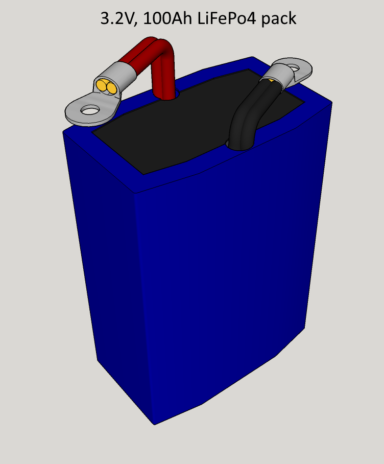
The p-groups will be wrapped in some thin vinyl or abs sheets and sealed with PVC heat shrink tubing. Once I have 32 of them made, they'll be connected in series with brass nuts and bolts and tinned copper lugs to form the 96V, 100Ah battery.
The p-groups will be wrapped in some thin vinyl or abs sheets and sealed with PVC heat shrink tubing. Once I have 32 of them made, they'll be connected in series with brass nuts and bolts and tinned copper lugs to form the 96V, 100Ah battery.
 |  |  |
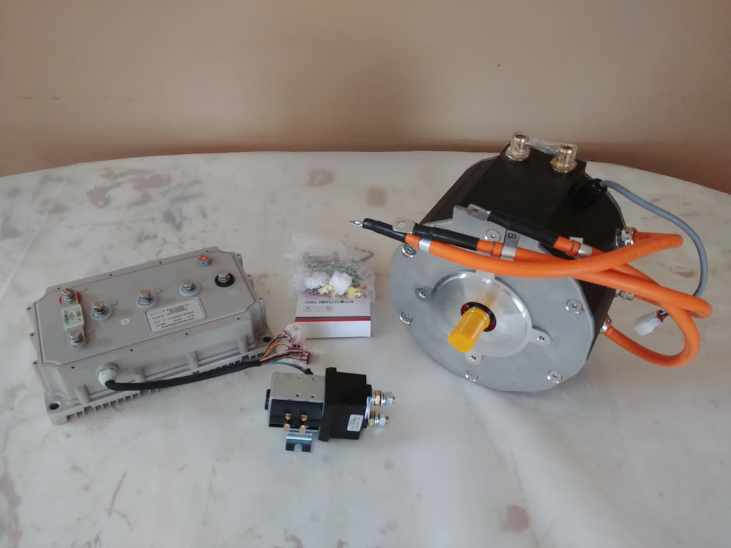
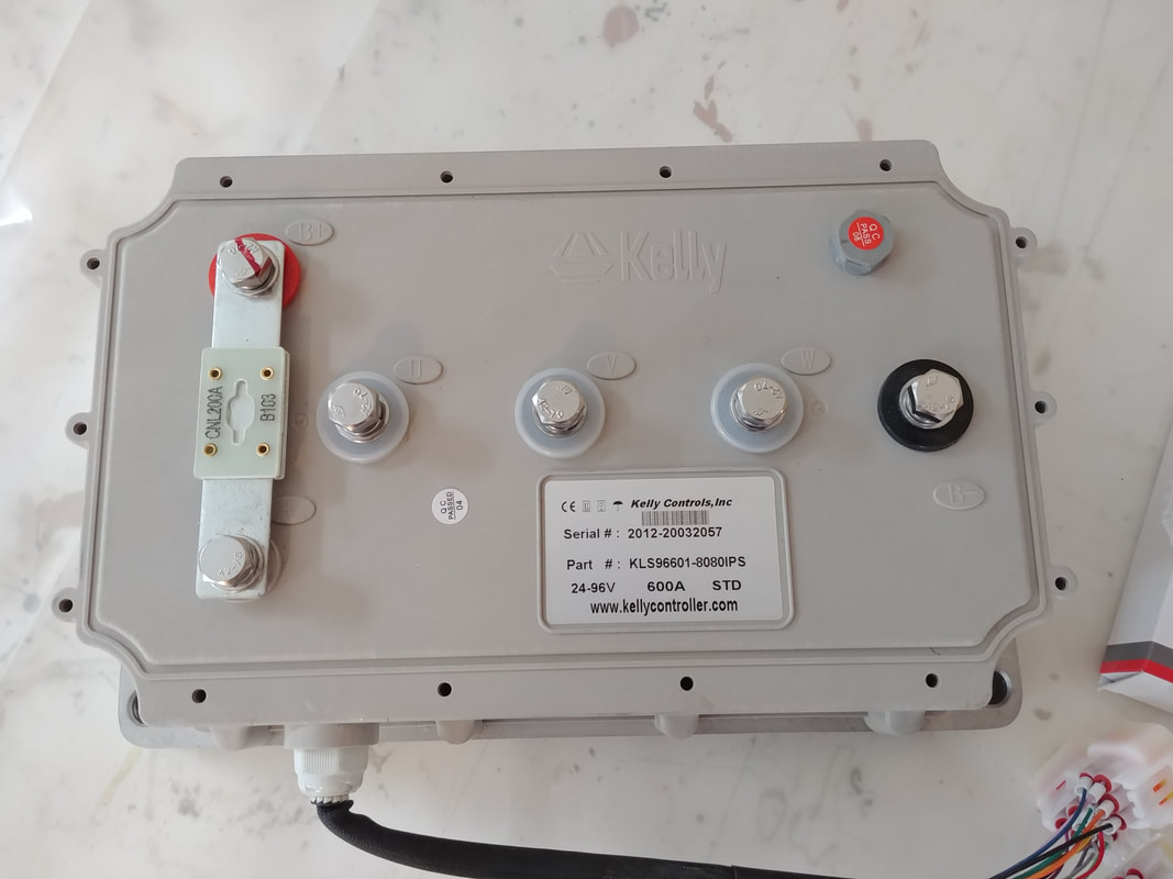
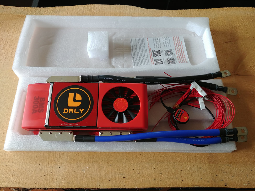
The bank will be connected to a 300A, 32S Daly BMS to keep the cells balanced and help protect the battery from overcharging/discharging. To control the motor, I'm using a KLS96601-8080IPS sinusoidal wave controller from kellycontroller.com. They actually sold me the motor and controller as a kit by request; they don't advertise the ME1616 on their website but they can provide it or any other Motenergy motor for you. Contact Fany at sales@kellycontroller.com for more information.
The controller is fully programmable, so everything from throttle response to speed to discharge and regen braking current can be adjusted via a PC or bluetooth and Android smartphone. Kelly makes reliable motor controllers, I've used them in almost all of my projects.
The controller is fully programmable, so everything from throttle response to speed to discharge and regen braking current can be adjusted via a PC or bluetooth and Android smartphone. Kelly makes reliable motor controllers, I've used them in almost all of my projects.
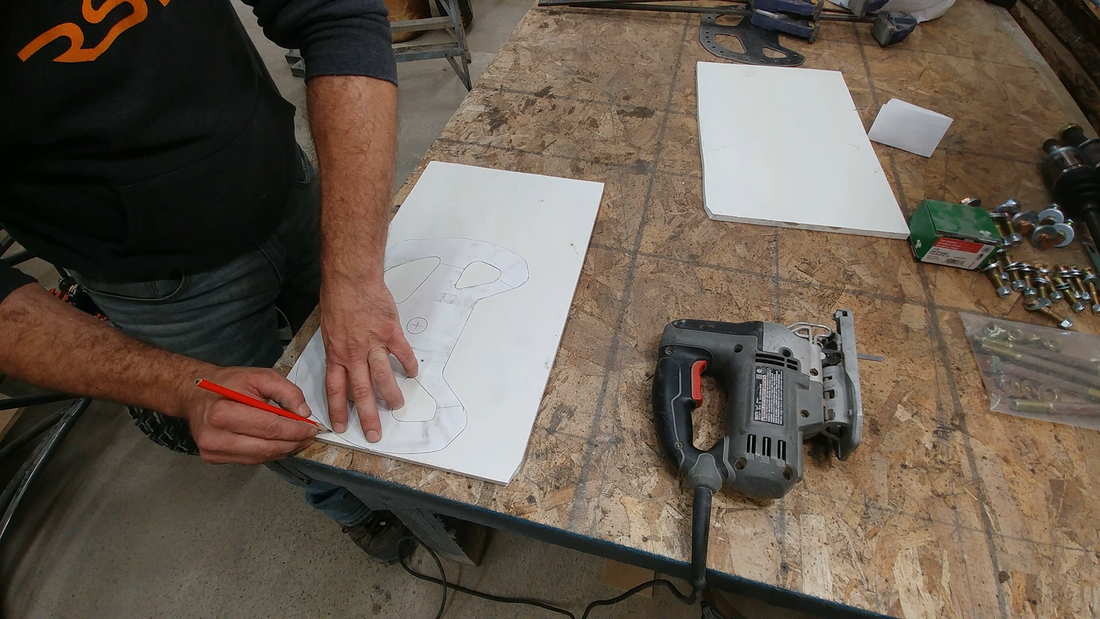
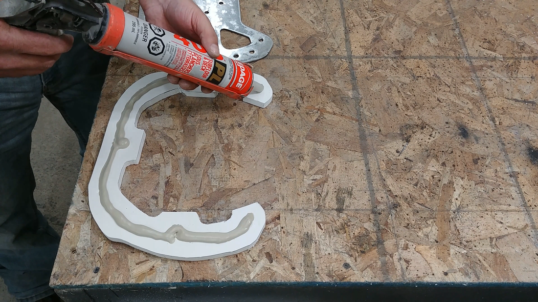
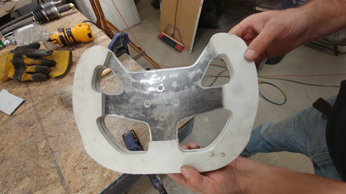
In this video I make a custom steering wheel for my electric crosskart buggy using 1/8" steel plate, 1/2" PVC foam board, and PL400 adhesive.
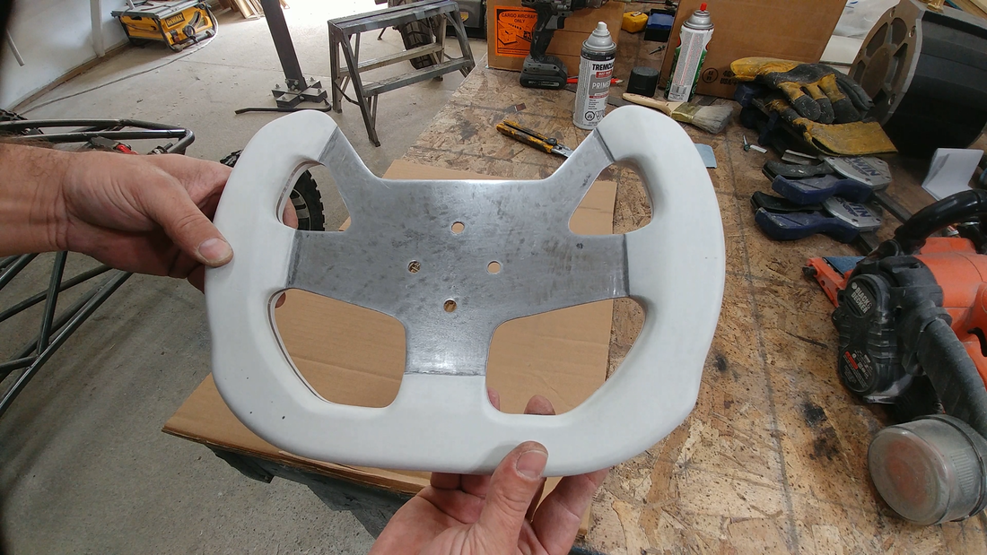
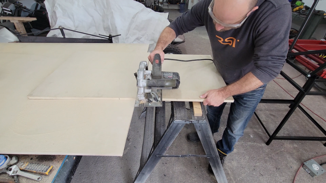
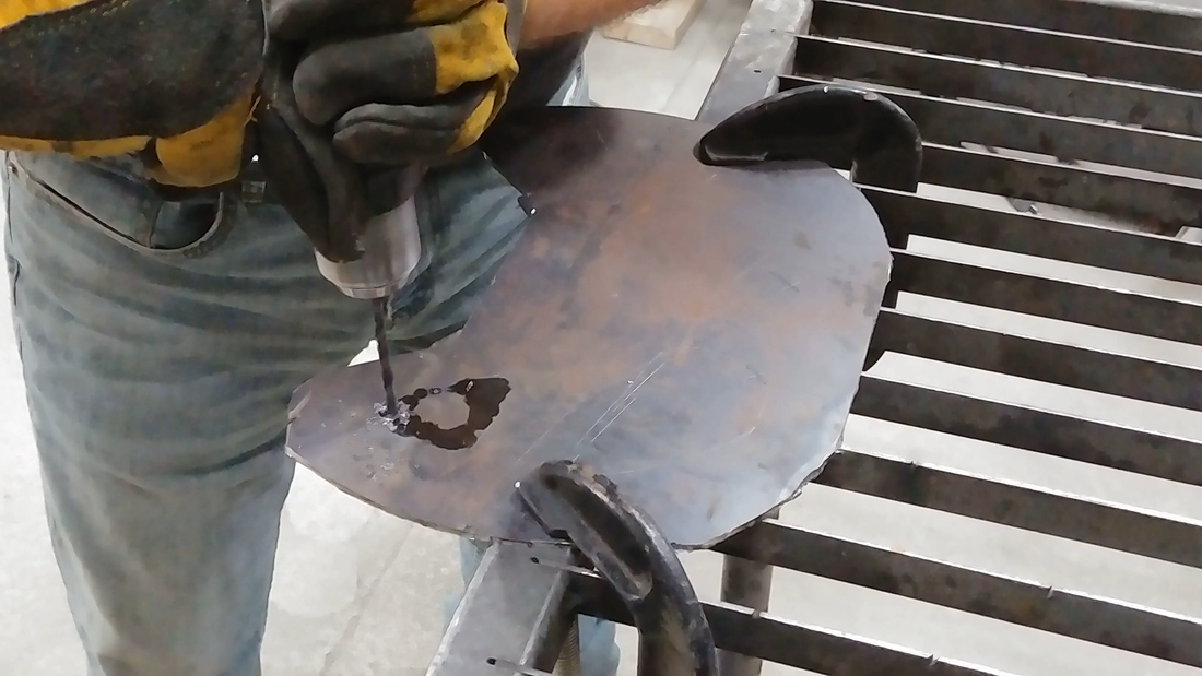
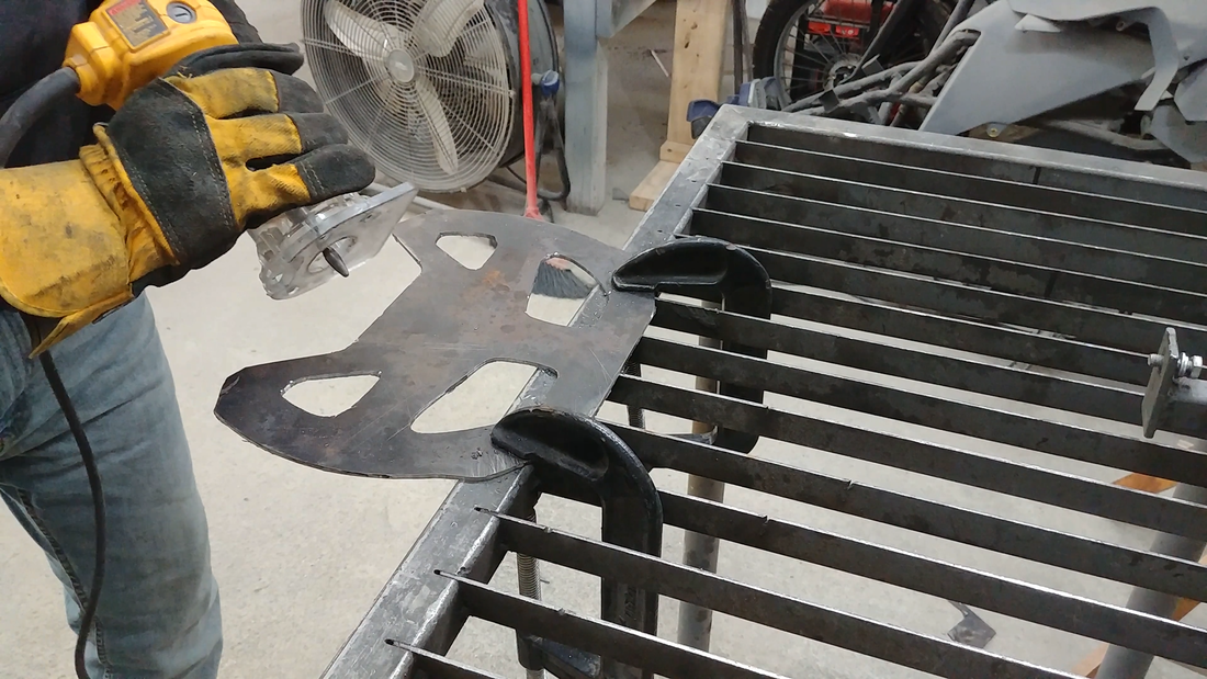
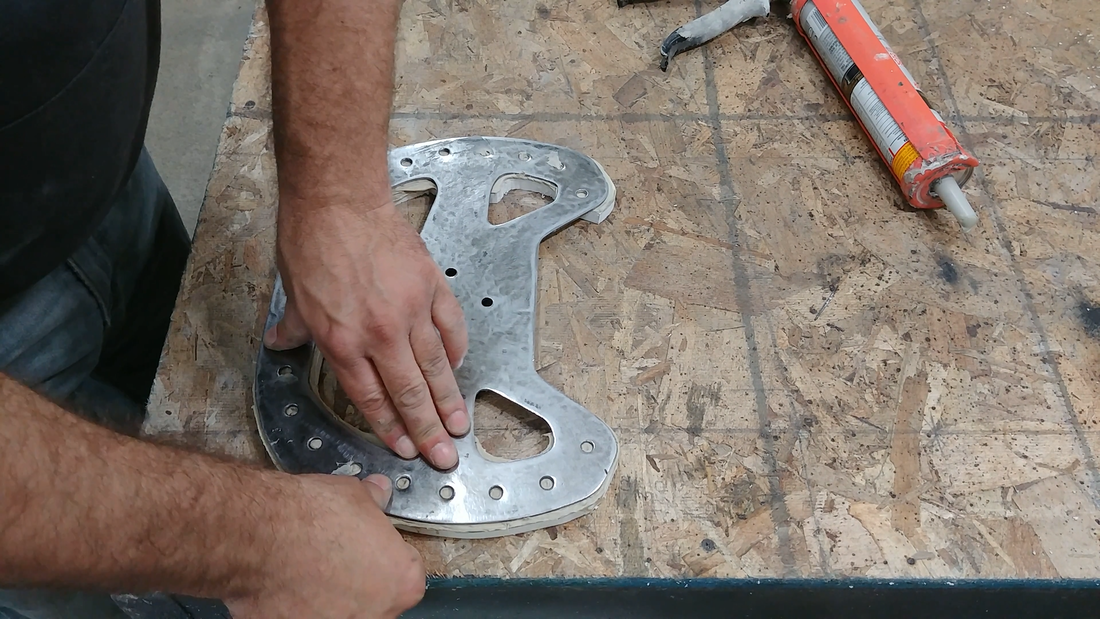
Why not just buy one? They're EXPENSIVE for something so simple. I wanted an open top, flat bottom steering wheel to give more leg room and an unobstructed view through the windshield. So I picked a design that I liked online, downloaded a jpg and scaled it to the size to create a template. I used a scratch awl to trace the outline of the template onto a sheet of 1/8" mild steel plate, then cut the perimeter with an angle grinder and cutting wheel.
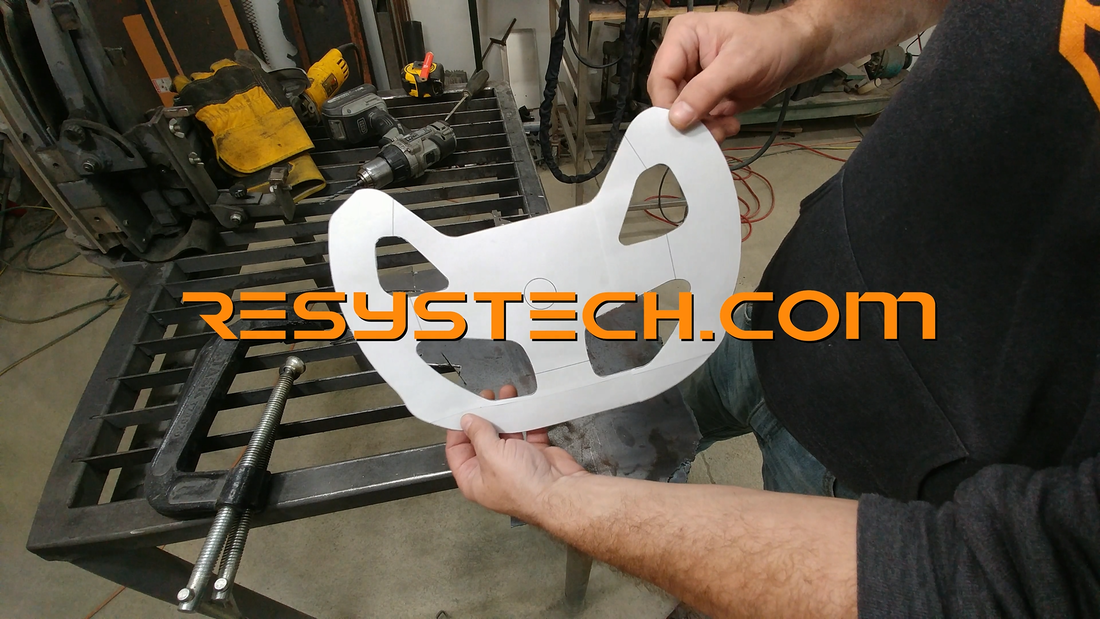
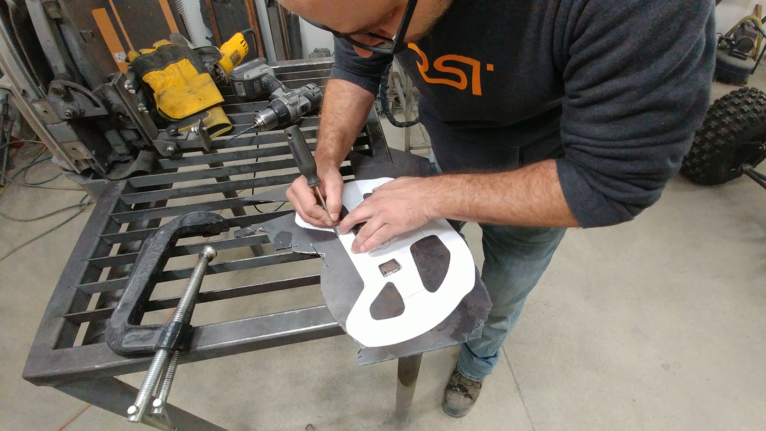
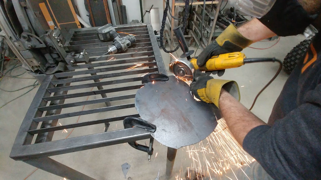
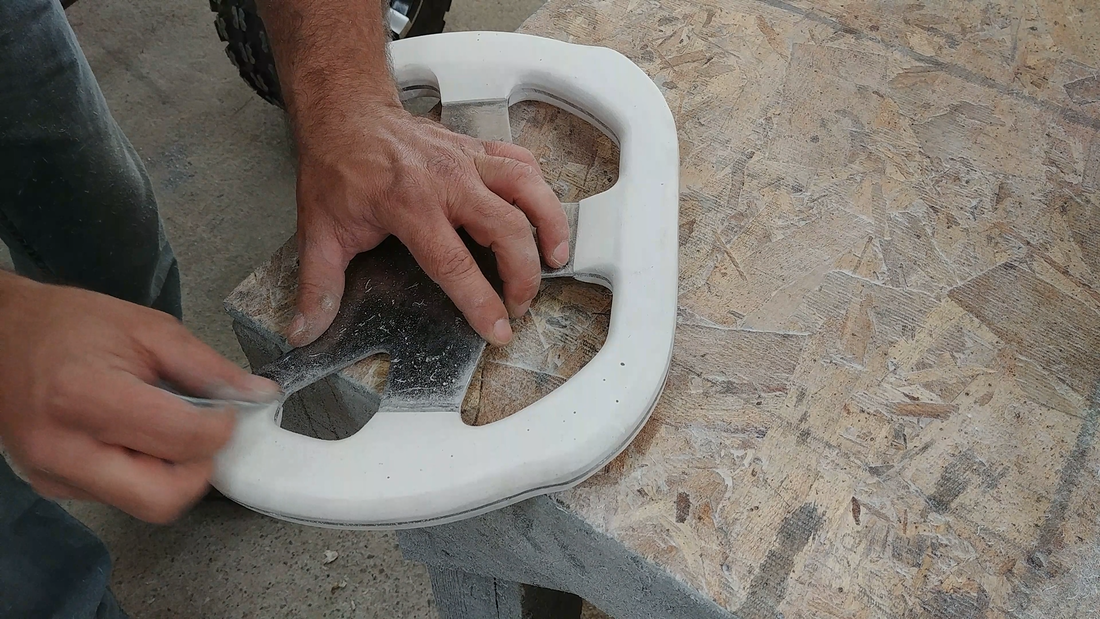
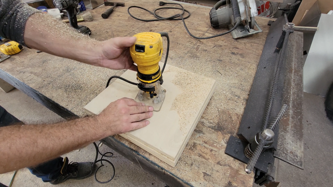
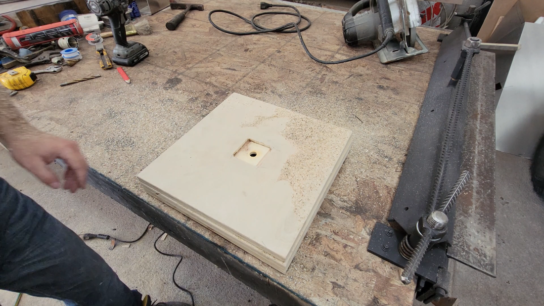
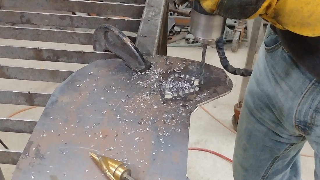
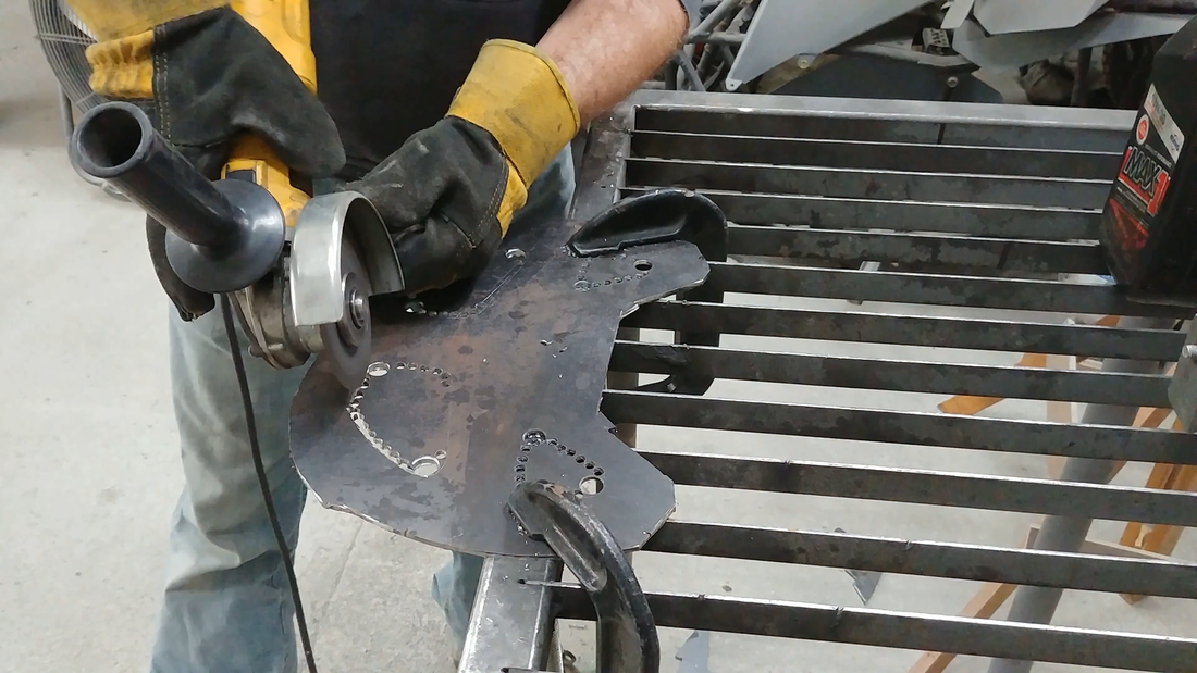
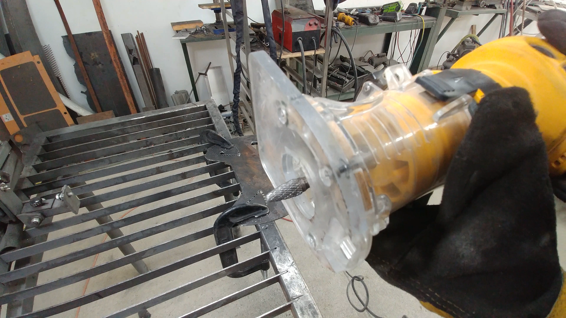
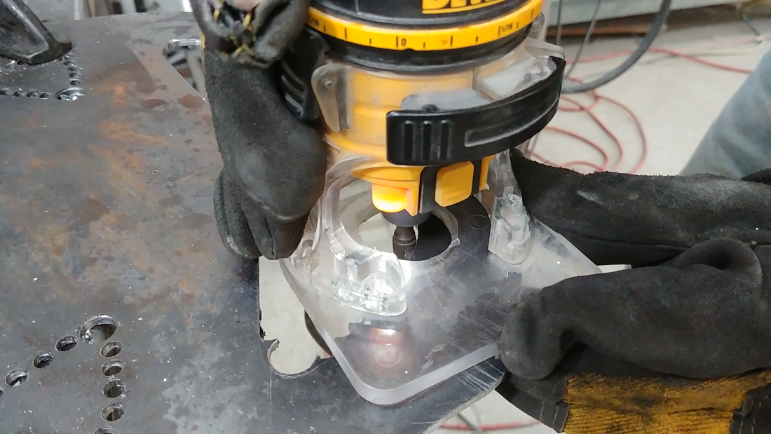
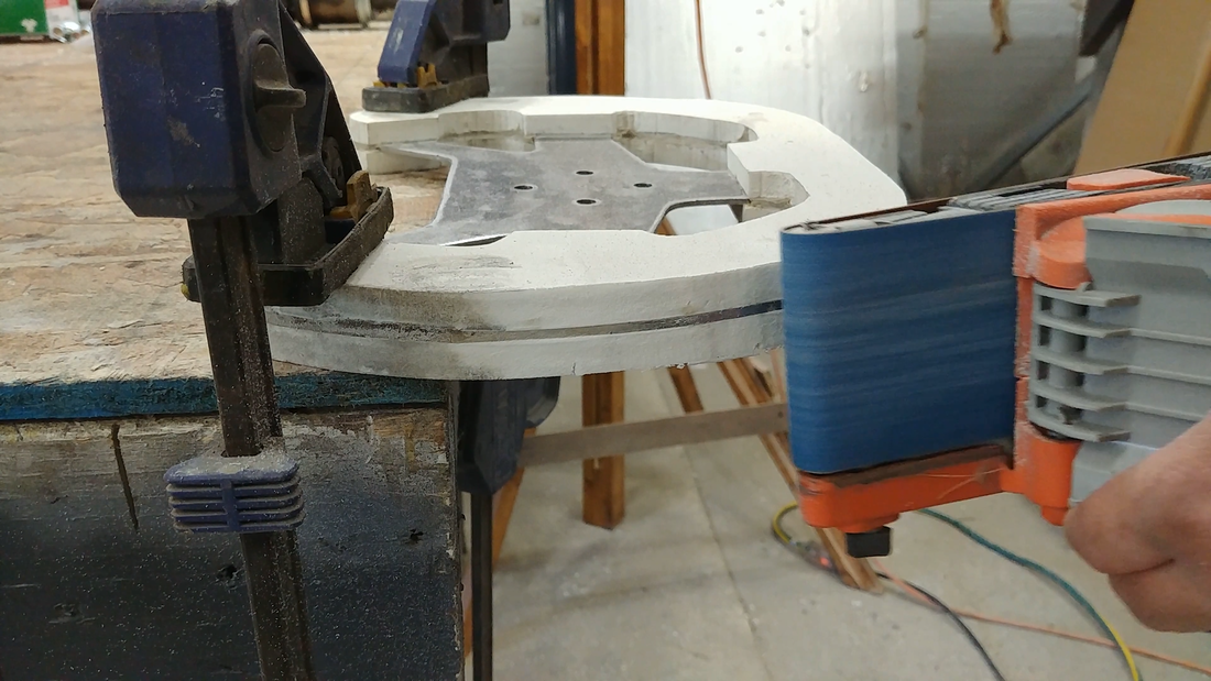
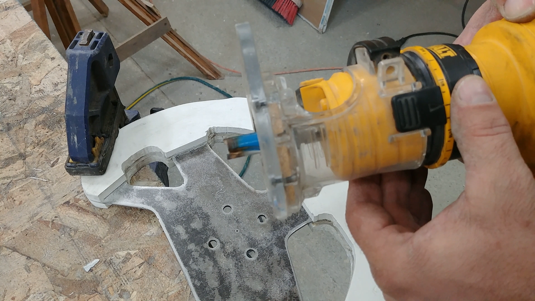
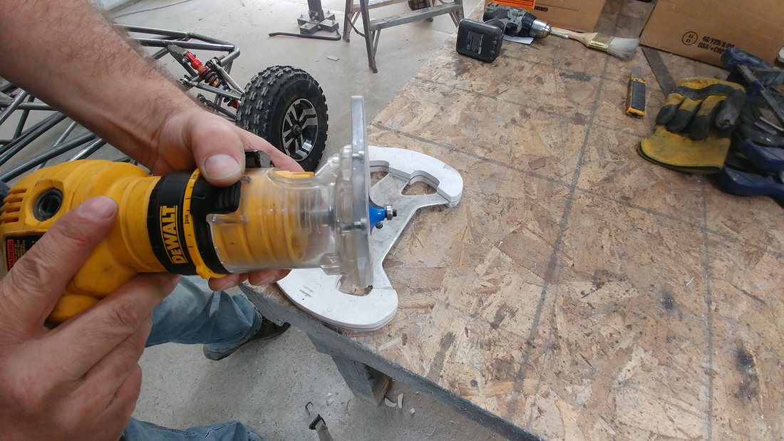
The cutting wheel on the grinder is less than ideal for cutting the holes for the grip. One option is to use a jigsaw with a metal cutting blade. I was concerned that the blade might jam up and distort the sheet metal as they sometimes do, so I decided to drill a series of small holes and cut out the majority of the waste with the angle grinder, then used a carbide burr bit in my trim router to clean the edges to the line. The burr bit is technically for a die grinder (a pneumatic Dremel type tool), but my compressor's tank capacity isn't large enough to keep up with it. But the bit and the trim router are rated for the same speed, so it worked just fine. A straight carbide router bit would also work, as I demonstrate later in the video when doing the final trimming.
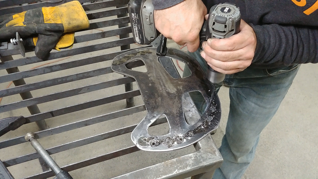
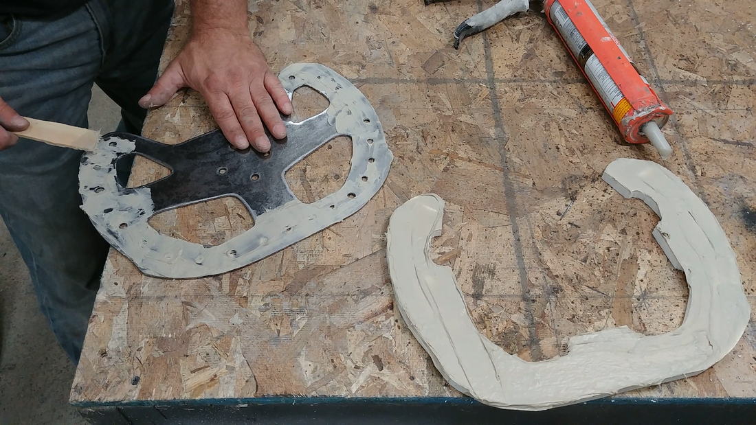
I then used a flap disc sander on the angle grinder to remove the mill scale from the sheet metal and rough up the surface, then drilled another series of holes around the perimeter of the steering wheel.
I then used a flap disc sander on the angle grinder to remove the mill scale from the sheet metal and rough up the surface, then drilled another series of holes around the perimeter of the steering wheel.
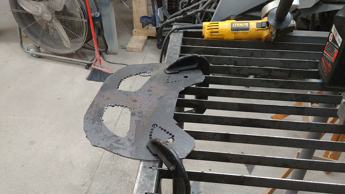
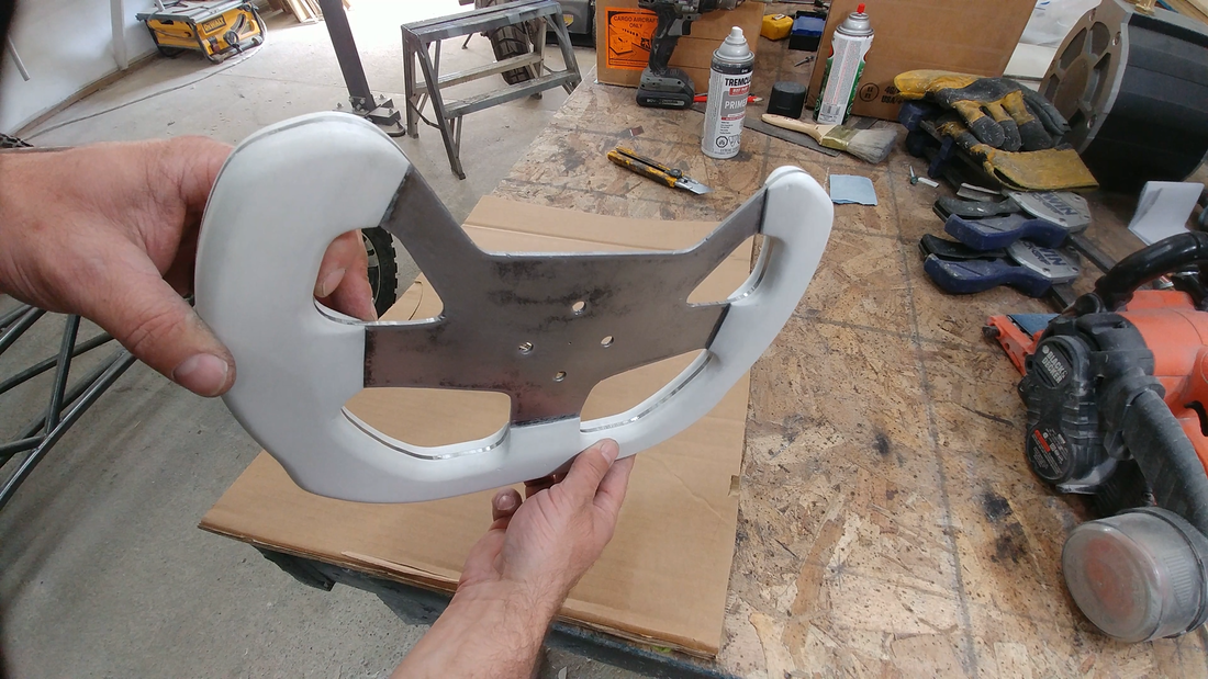
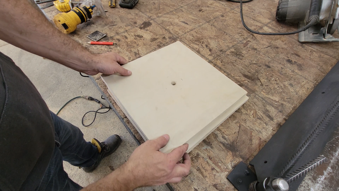
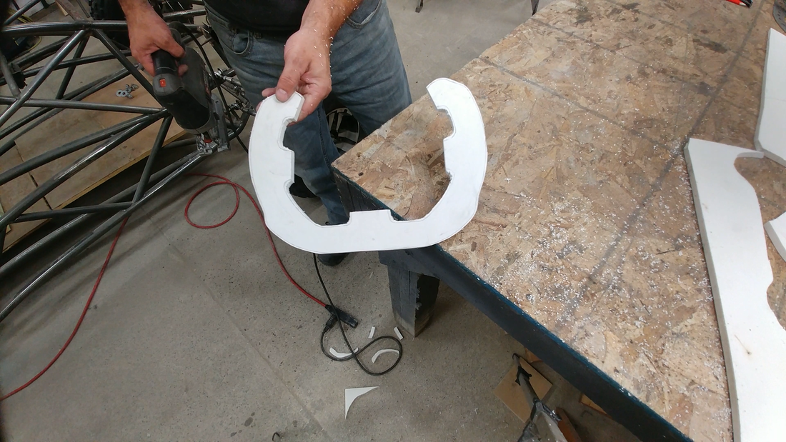
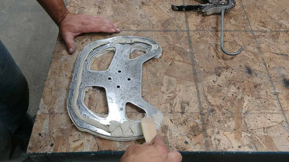
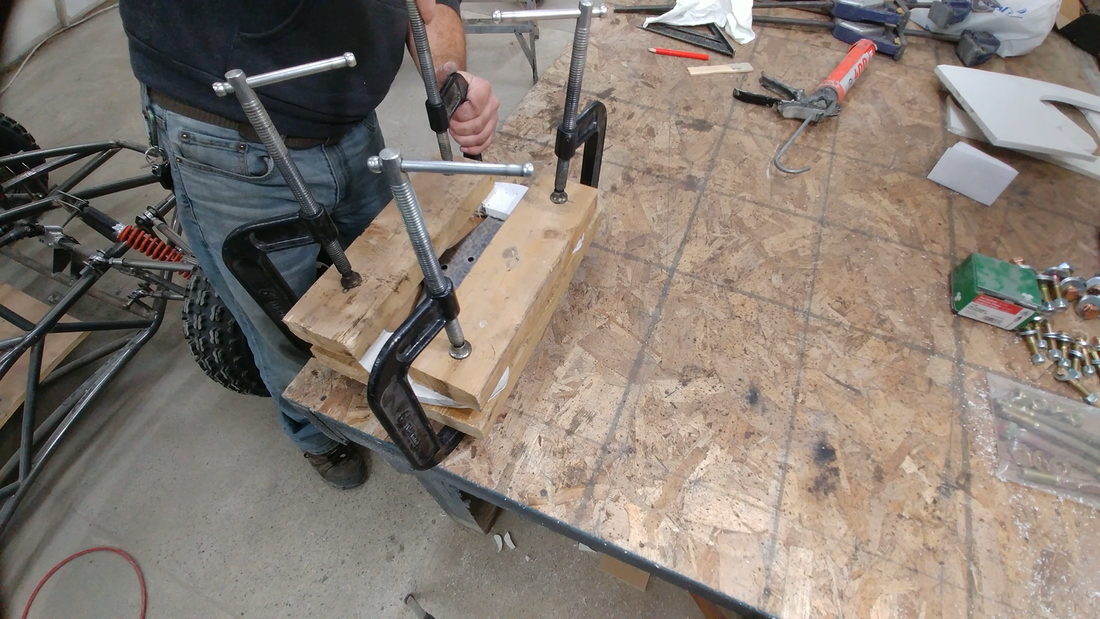
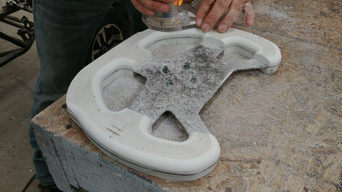
I traced the template onto a piece of 1/2" PVC foam and cut two profiles of the steering wheel from it with a jigsaw, then roughed up the faces with sand paper and cleaned them of debris. These will form the actual grip for the steering wheel. I applied a layer of PL400 adhesive to one side of one PVC piece and to the corresponding side of the sheet metal 'frame', then pressed them together until the adhesive oozed from the sides and through the holes drilled into the frame. Then I applied another layer of PL400 onto the other faces of the frame and PVC and sandwiched the laminations together using clamps, and left it overnight to cure.
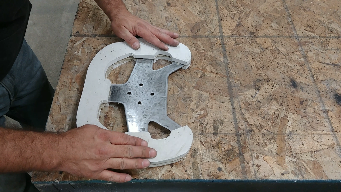
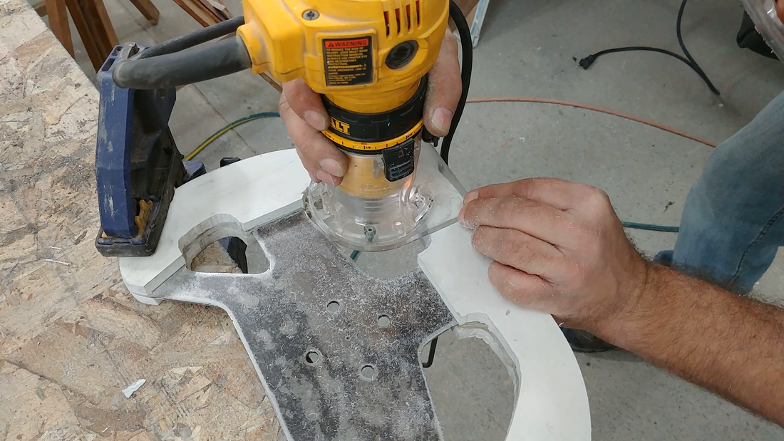
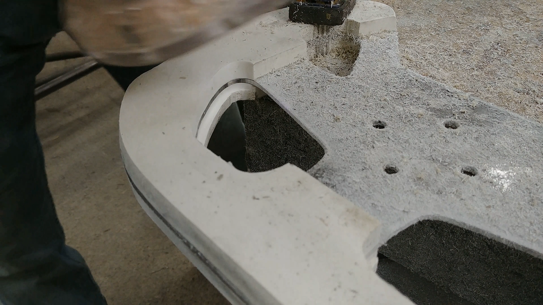
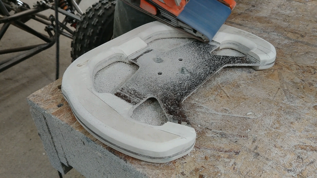
The next day, I cleaned up the edges of the steering wheel and started forming the grip with a belt sander. Using the trim router with a straight carbide router bit set to just half the thickness of the steering wheel, I flushed up one side of the PVC with the steel frame. Then I used a flush trim bit to perfectly trim the other side to the first. A round over bit finished all of the PVC edges so the steering wheel is comfortable to grip.
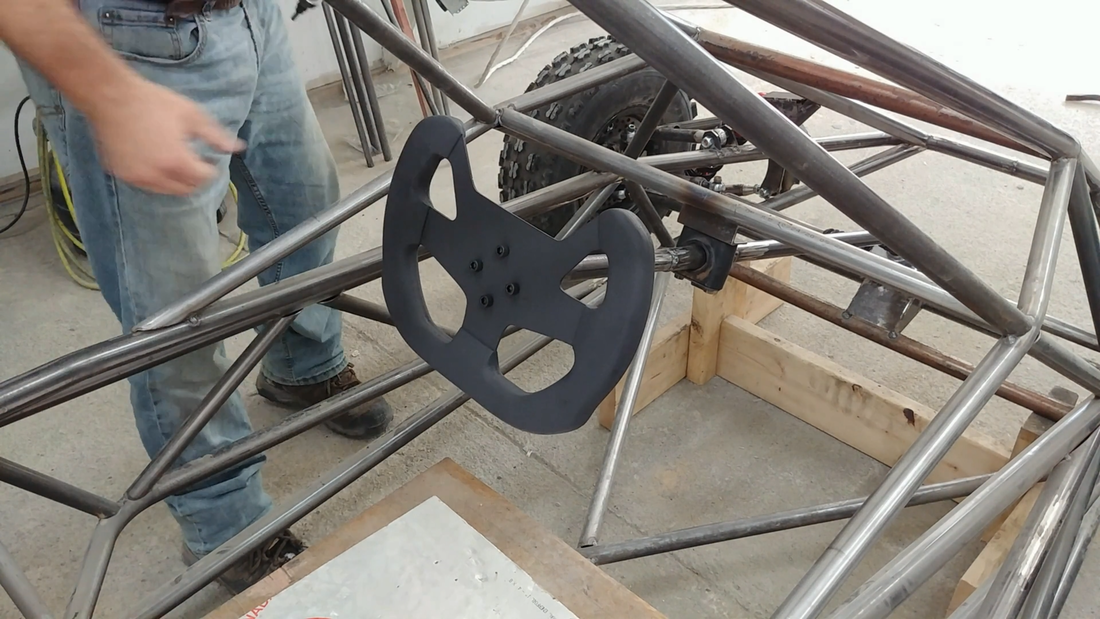
After a bit of hand sanding with some fine sandpaper, I painted the steering wheel matte black. I would have preferred to use black PVC instead of painting it, but I already had some white PVC scraps that I wanted to use up. Another more affordable option for the grip could have been wood with a strong polyurethane finish.