- Empty Cart
|
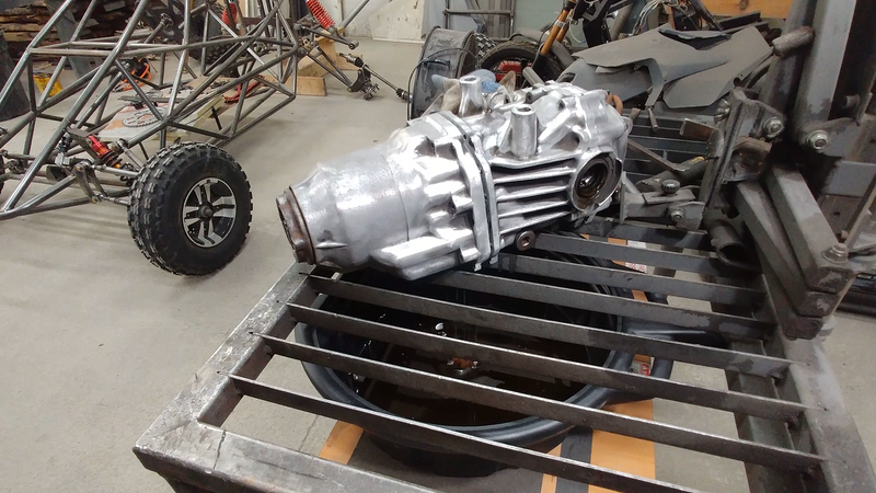
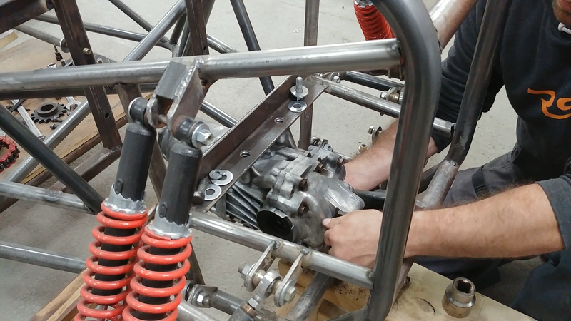
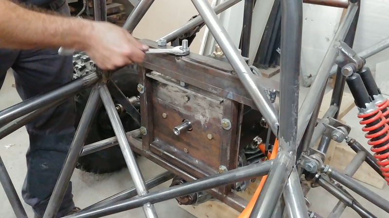
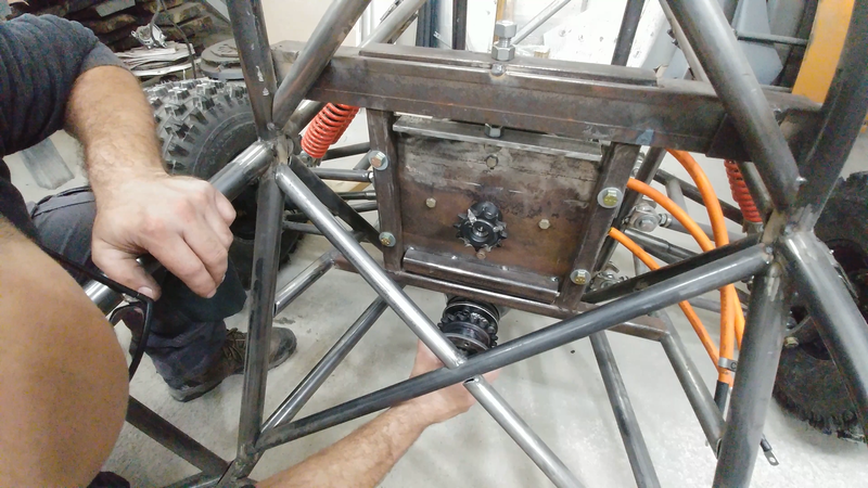
In this video I fit the drivetrain to the electric crosskart chassis. I'm using a rear open differential from a 2007 Honda AWD CR-V to transmit power from the motor to the rear axles. It's light and compact, and will eliminate any understeering that would otherwise happen with a solid axle. But a couple of mod's need to be done to make it more suitable for the crosskart. For ex, a limited slip diff would be ideal; when one wheel spins, the LSD would automatically lock up the other wheel so both have traction. A cheap LSD conversion kit is available for this differential and will be installed before the final assembly (after paint).
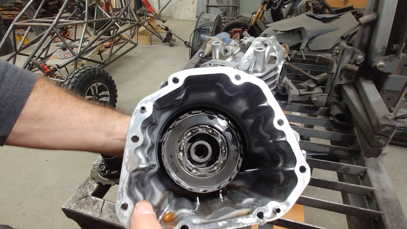
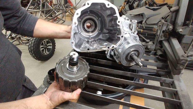
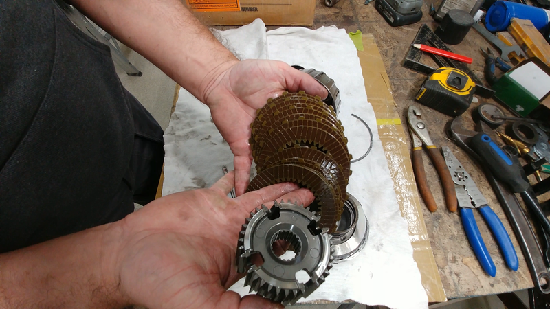
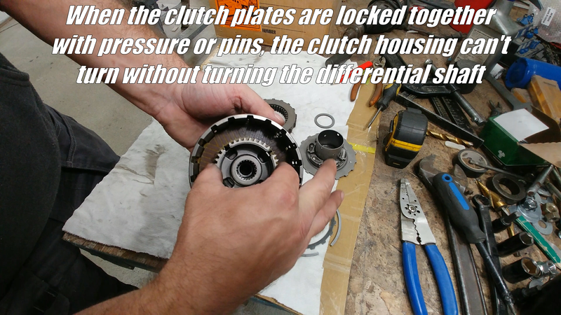
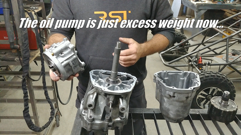
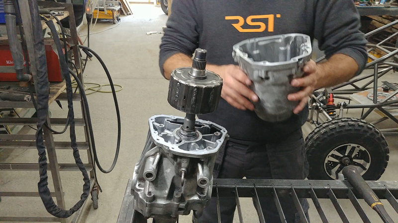
Another mod that must happen is pinning the clutch pack located in the front of the diff. Being an AWD, the input shaft from the rear diff rotates freely inside the clutch pack in normal conditions. When the front wheels slip, the pump located behind the clutch pack automatically forces oil into the back of the pack which puts pressure on the clutch plates to lock the clutch pack and diff shaft together and transmit power to the rear wheels.
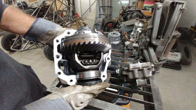
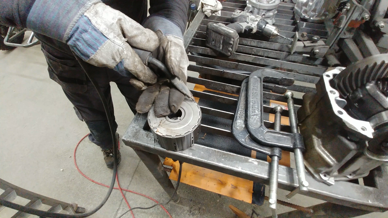
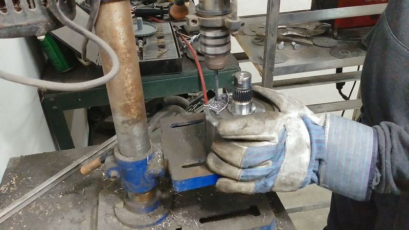
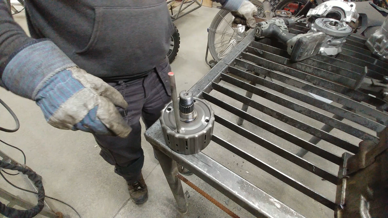
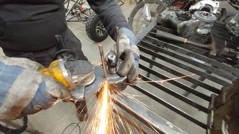
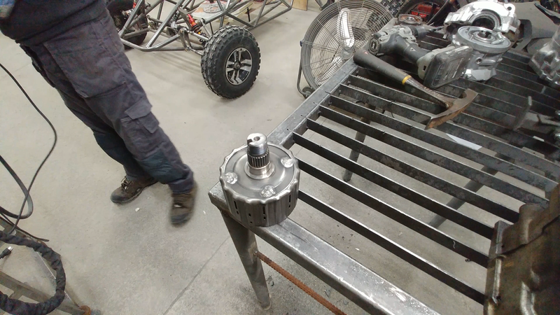
If the differential is installed without dealing with the clutch pack, then it'll cause a slip and lag in response every time I use the throttle. To get around this problem, I drilled and pinned the clutch plates to the clutch housing so that it's permanently locked to the diff's input shaft. The oil pump was removed completely, since the clutch is no longer a clutch and the pump would just be dead weight. I bolted everything back together and fit the differential to the chassis.
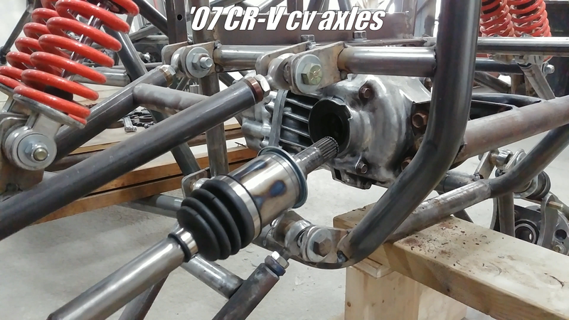
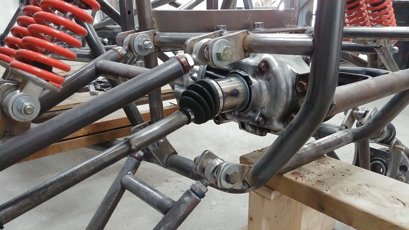
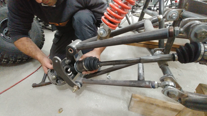
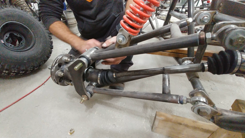
I then installed the cv axles, which were shortened from their original length (to keep the track width at 62" with the offset wheels) by removing the required amount from as close to the inner joint as possible, then grinding the cut ends to a 45° point and welding them back together. Then a 4" long DOM tube sleeve was slipped over the joint and welded. Ideally, you shouldn't do this. A cv axle is technically a torsion bar, ie: a spring. It's intended to flex with the torsional force created when the diff twists the axles to turn the wheels. If the shafts re too brittle, they'll break. This method increases that risk, which is why I didn't show it in the video but I'm curious to see how they hold up. The best way to shorten the shafts is to take them to a local machine shop and have them disassemble the cv joint so they can cut the shaft to length and re-spline the end to fit the joint again. It'll cost, but you won't have to worry about it when you're messing around on a trail in the middle of nowhere.
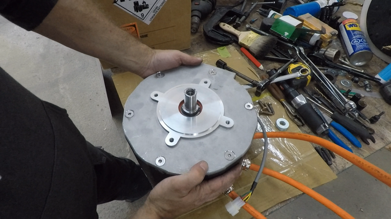
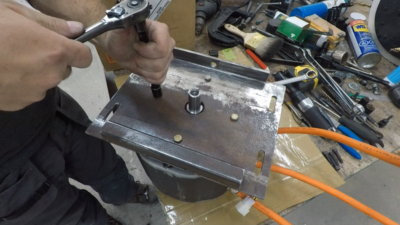
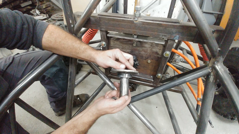
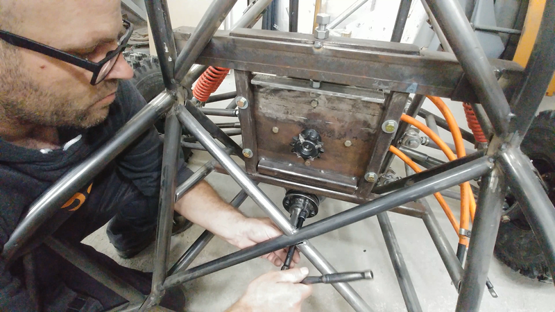
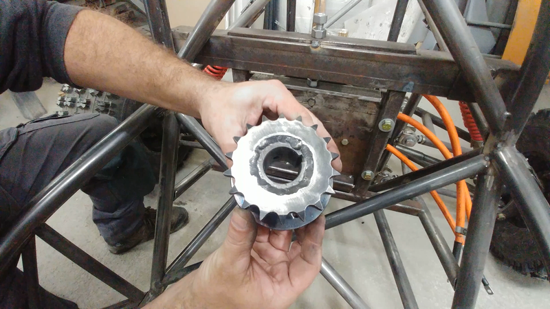
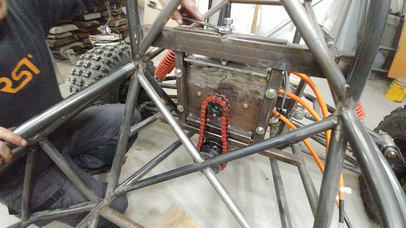
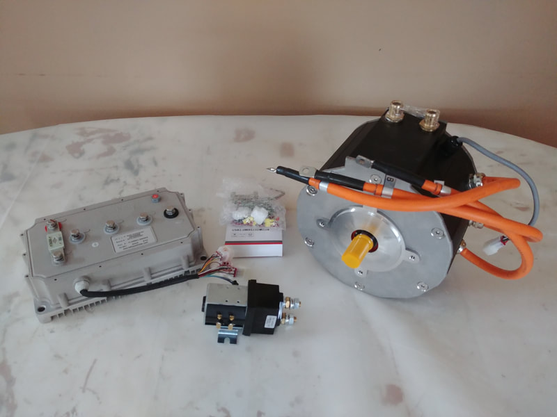
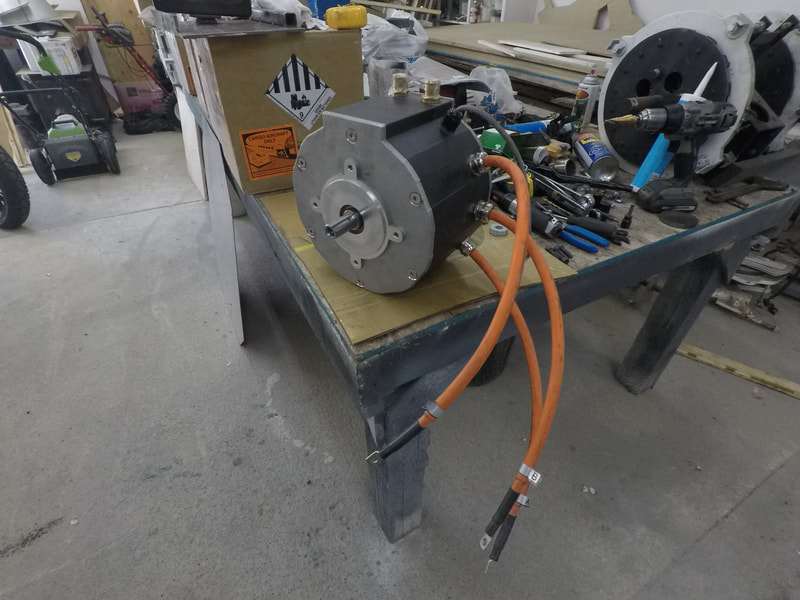
The differential has a 16T drive pinion and a 41T drive gear = a gear ratio of 2.56:1. I'm using a 12T drive sprocket with a 7/8" keyed weld-on hub on the 55 kW ME1616 motor and linking it to a 18T sprocket with a 1-1/4" keyed weld-on hub connected to a keyed stainless steel shaft that I welded another hub and plate to which was bolted to the diff's output shaft. Total sprocket ratio is 3.84:1. The sprockets are driven by a 530 o-ring chain. The motor is mounted to a plate with elongated bolt holes and a piece of 90° angle welded to the top, which a 1/2"-13 threaded rod is fastened to and serves as part of the chain tensioner.
With the 22" wheels and a max motor rpm of 6000 (~1500 at the wheels), the top speed should be around 160 km/h (~100 mph). The motor is capable of 0.33 nm (0.24 ft-lb) of constant torque per amp which amounts to around 82 nm (60 ft-lb) continuous or ~180 nm (132 ft-lb) at peak power at the motor shaft, so the gearing should bump it up to close to 316 nm (233 ft-lb) continuous, 700 nm (500 ft-lb) peak at the wheels.
The rear brakes, again from a Yamaha Banshee, will be mounted in front of the motor instead of the axles, and will consist of one large rotor with two hydraulic calipers, both of which have a spring loaded mechanical parking/emergency brake feature that will be connected to a cable and lever in the cockpit.
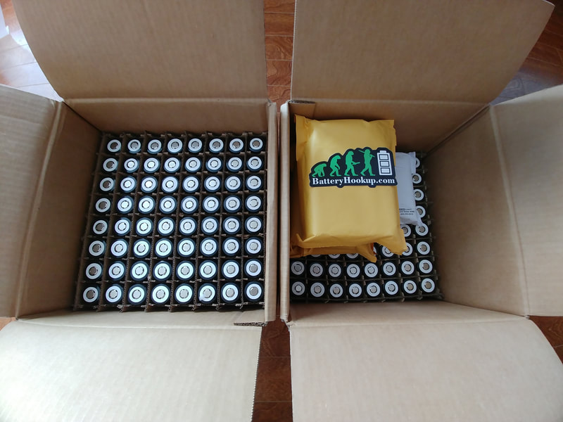
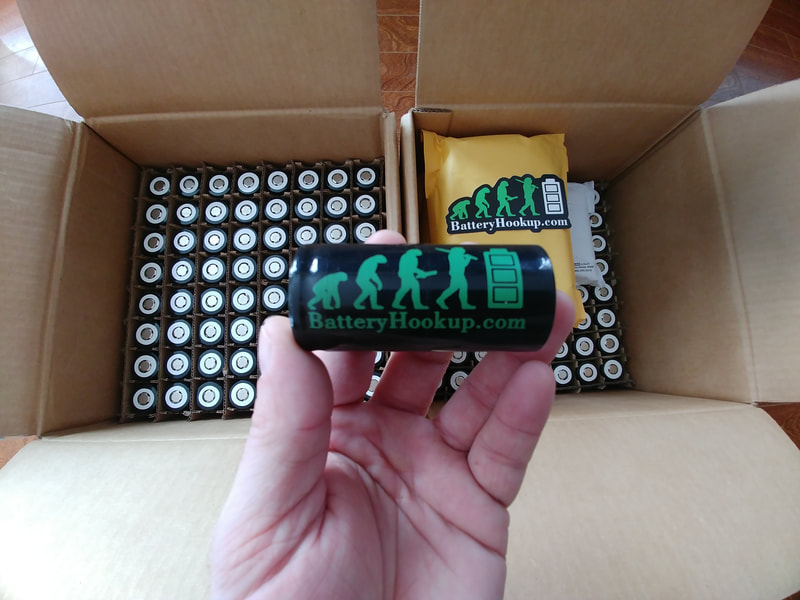
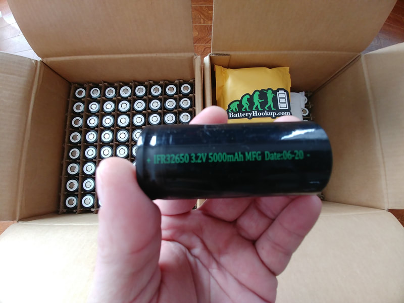
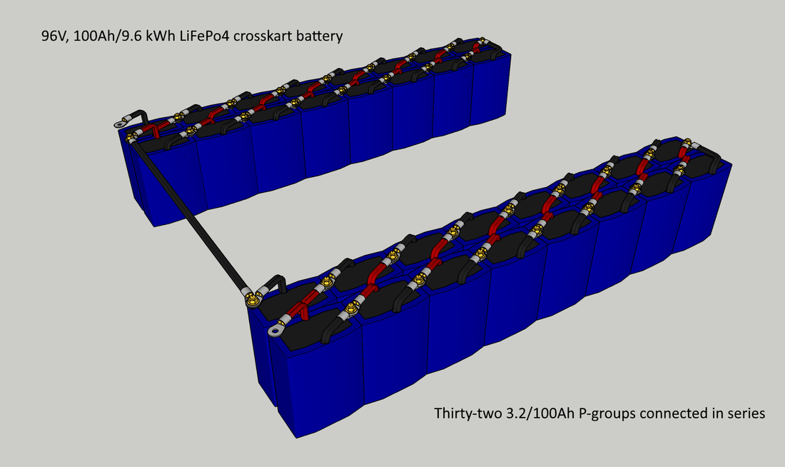
I've decided to make the battery a bit smaller than originally planned, to save some space and weight. Instead of a 24P32S pack of the 5000mAh LiFePo4 cells from batteryhookup.com for 11.5 kWh @ 96V, I'm building a 20P32S pack for 9.6 kWh @ 96V.
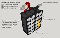
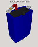
I'll connect 20 of the 3.2V, 5Ah batteryhookup cells in parallel to form a larger 3.2V, 100Ah cell or 'p-group' using 0.25x15mm nickel strips and 2 awg copper bus wire; the nickel strips will be soldered directly to two bus wires on each side of the pack first to avoid overheating the cells, then the strips will be spot welded to each cell. The purpose of the bus wires is to eliminate the need to spot weld 4 or 5 layers of nickel strips for the series connections, which would add more work and force me to make the battery in one or two large and awkward to handle blocks. Instead, I'll be able to install the battery into the crosskart one p-group at a time, and easily connect/disconnect them with a couple of wrenches.
I had considered using tinned copper busbars, but they're way too expensive. Tinned wire is cheaper. Aluminum busbars would be another more affordable option if it were possible to solder or spot weld the nickel to it successfully, but most attempts by others in the past have had subpar results if not complete fails. The nickel strips could be connected to the aluminum using screws and large flat washers, but having current flowing through the screws and the crosskart being bumped around in the trails might cause them to vibrate and work lose over time and I didn't want to have to tear open the packs to inspect them on a periodic basis.
The p-groups will be wrapped in some thin vinyl or abs sheets and sealed with PVC heat shrink tubing. Once I have 32 of them made, they'll be connected in series with brass nuts and bolts and tinned copper lugs to form the 96V, 100Ah battery.
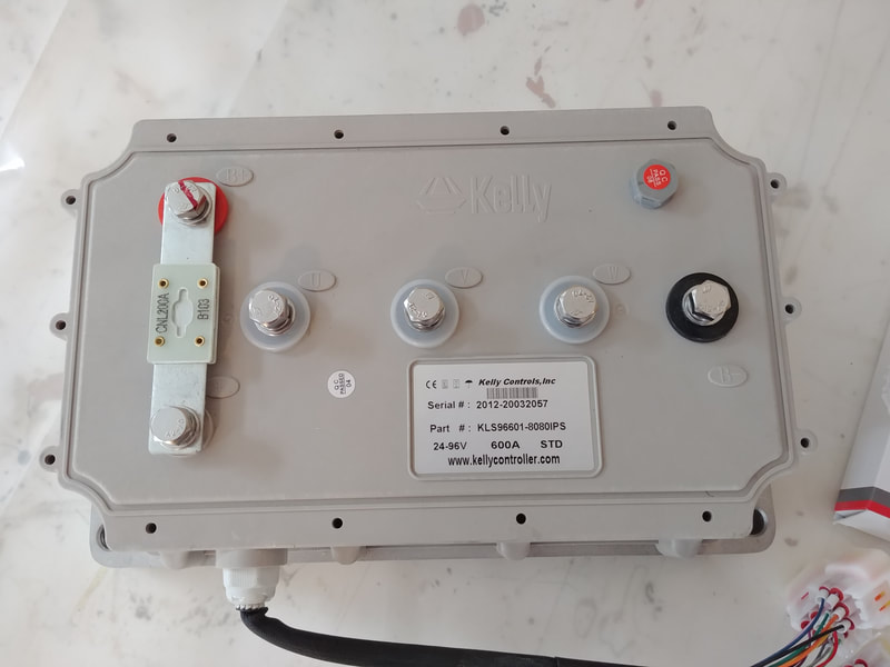
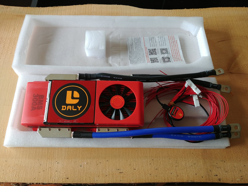
The bank will be connected to a 300A, 32S Daly BMS to keep the cells balanced and help protect the battery from overcharging/discharging. To control the motor, I'm using a KLS96601-8080IPS sinusoidal wave controller from kellycontroller.com. They actually sold me the motor and controller as a kit by request; they don't advertise the ME1616 on their website but they can provide it or any other Motenergy motor for you. Contact Fany at sales@kellycontroller.com for more information.
The controller is fully programmable, so everything from throttle response to speed to discharge and regen braking current can be adjusted via a PC or bluetooth and Android smartphone. Kelly makes reliable motor controllers, I've used them in almost all of my projects.
2 Comments
Michael
8/9/2021 02:27:30 pm
Wondering about the battery packs with the busbars. I see mostly how-to's on YouTube that show the laying of multiple strips of nickel, but the way you've got it laid out seems a lot more friendly to make. Will you be doing a video of the making?
Reply
Harry
1/30/2023 02:46:03 am
How did you decide on a 55kW motor? I'm looking to do a similar project but I'm having trouble figuring out what size motor I need.
Reply
Leave a Reply. |
AuthorJames Biggar Archives
March 2023
Categories |


 RSS Feed