|
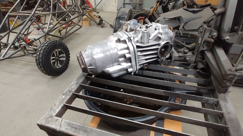
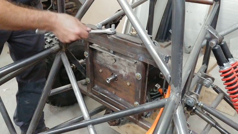
In this video I fit the drivetrain to the electric crosskart chassis. I'm using a rear open differential from a 2007 Honda AWD CR-V to transmit power from the motor to the rear axles. It's light and compact, and will eliminate any understeering that would otherwise happen with a solid axle. But a couple of mod's need to be done to make it more suitable for the crosskart. For ex, a limited slip diff would be ideal; when one wheel spins, the LSD would automatically lock up the other wheel so both have traction. A cheap LSD conversion kit is available for this differential and will be installed before the final assembly (after paint).
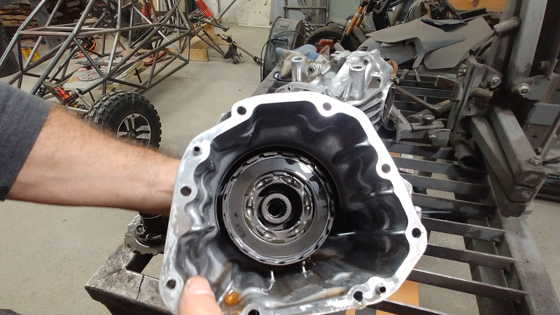
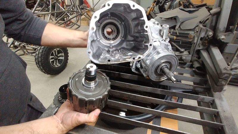
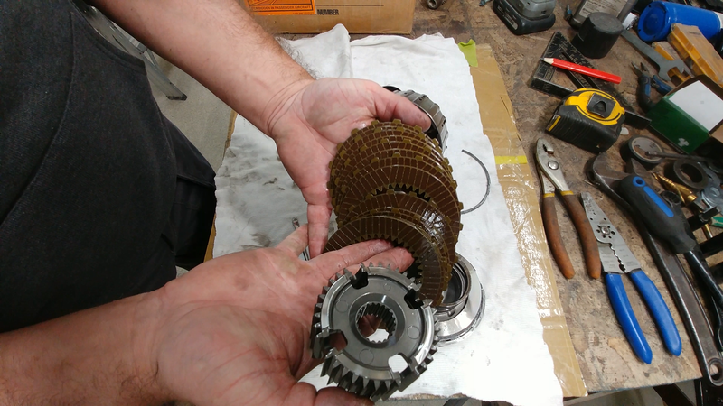
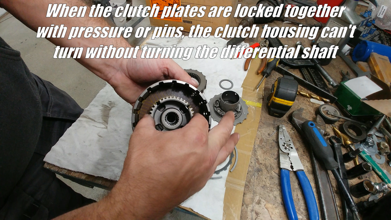
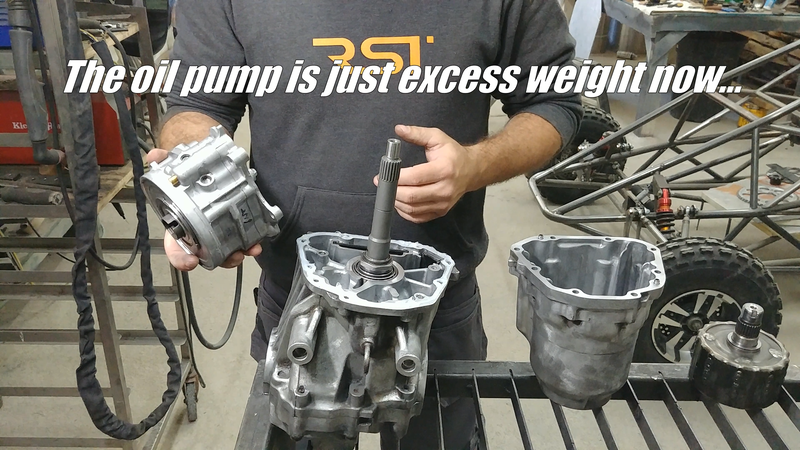
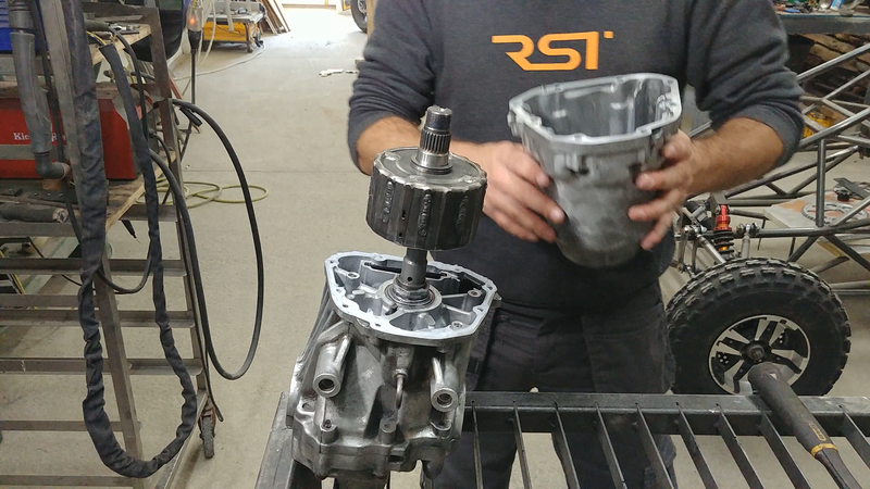
Another mod that must happen is pinning the clutch pack located in the front of the diff. Being an AWD, the input shaft from the rear diff rotates freely inside the clutch pack in normal conditions. When the front wheels slip, the pump located behind the clutch pack automatically forces oil into the back of the pack which puts pressure on the clutch plates to lock the clutch pack and diff shaft together and transmit power to the rear wheels.
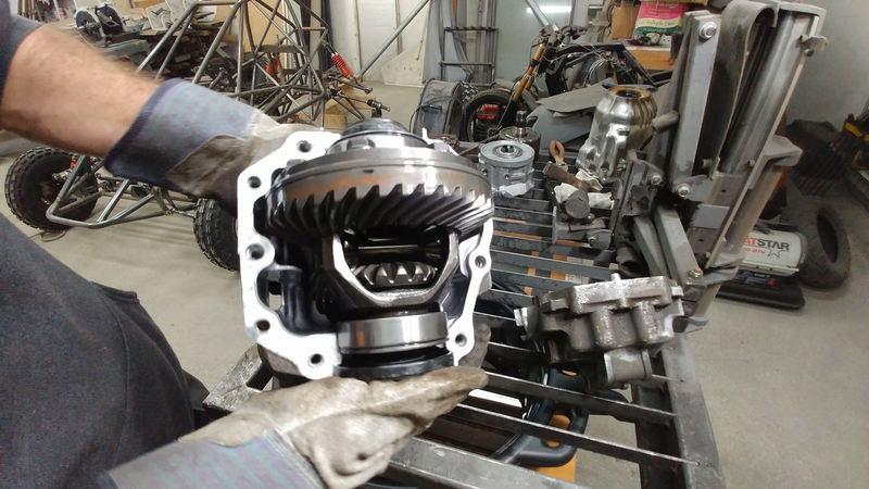
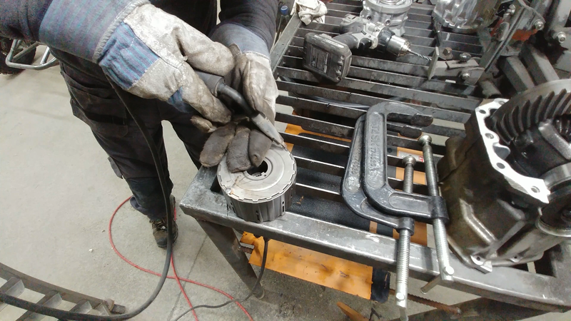
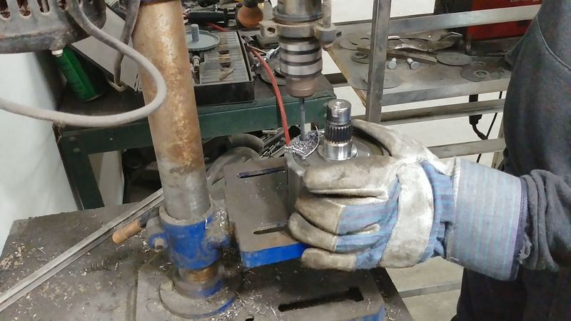
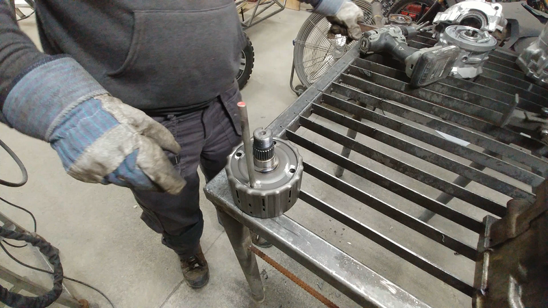
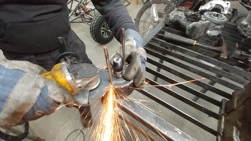
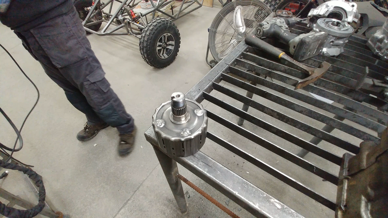
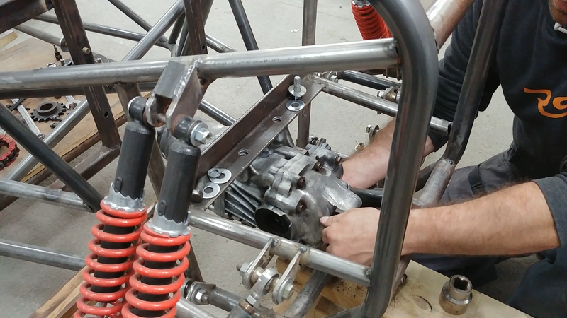
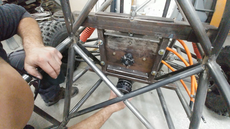
If the differential is installed without dealing with the clutch pack, then it'll cause a slip and lag in response every time I use the throttle. To get around this problem, I drilled and pinned the clutch plates to the clutch housing so that it's permanently locked to the diff's input shaft. The oil pump was removed completely, since the clutch is no longer a clutch and the pump would just be dead weight. I bolted everything back together and fit the differential to the chassis.
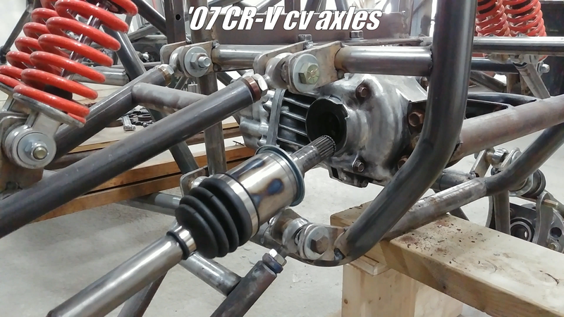
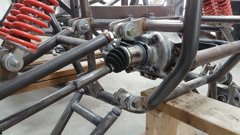
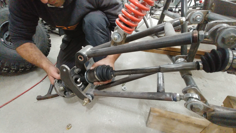
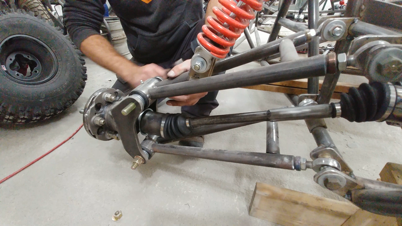
I then installed the cv axles, which were shortened from their original length (to keep the track width at 62" with the offset wheels) by removing the required amount from as close to the inner joint as possible, then grinding the cut ends to a 45° point and welding them back together. Then a 4" long DOM tube sleeve was slipped over the joint and welded. Ideally, you shouldn't do this. A cv axle is technically a torsion bar, ie: a spring. It's intended to flex with the torsional force created when the diff twists the axles to turn the wheels. If the shafts re too brittle, they'll break. This method increases that risk, which is why I didn't show it in the video but I'm curious to see how they hold up. The best way to shorten the shafts is to take them to a local machine shop and have them disassemble the cv joint so they can cut the shaft to length and re-spline the end to fit the joint again. It'll cost, but you won't have to worry about it when you're messing around on a trail in the middle of nowhere.
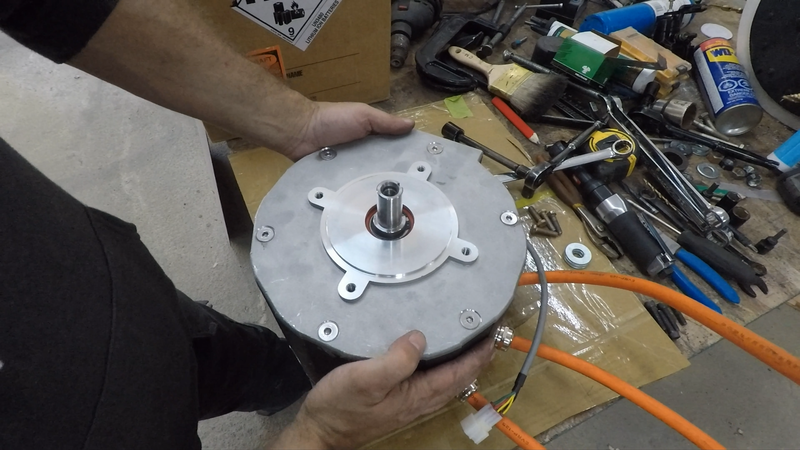
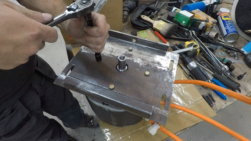
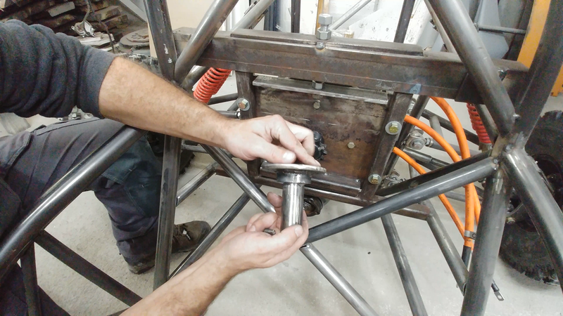
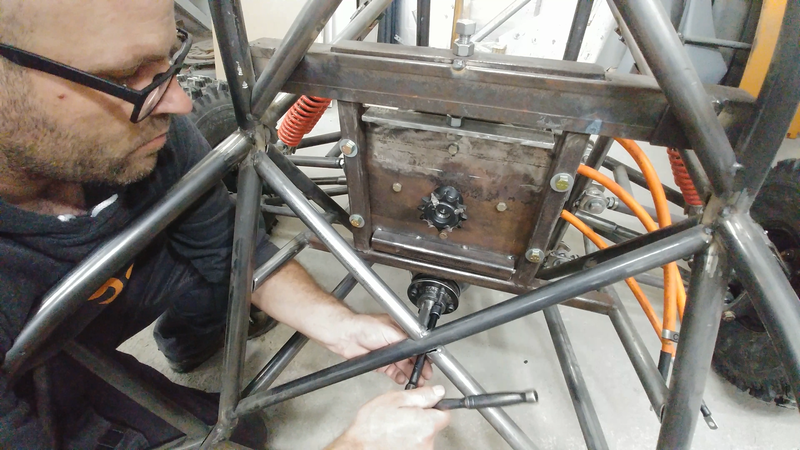
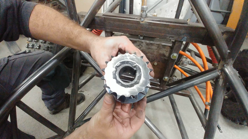
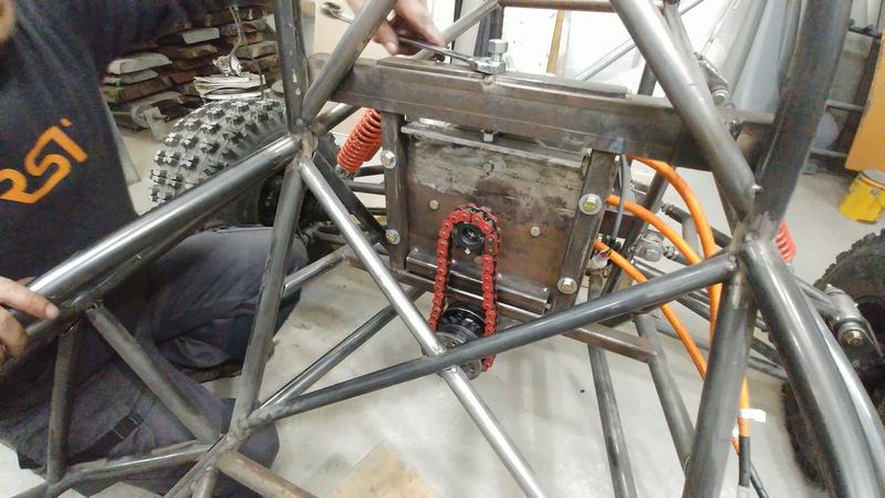
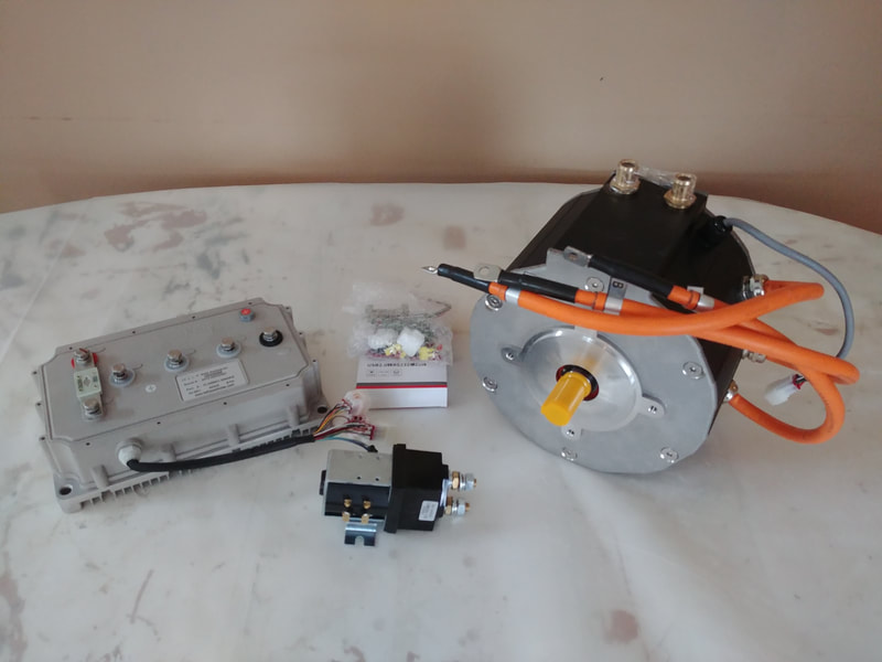
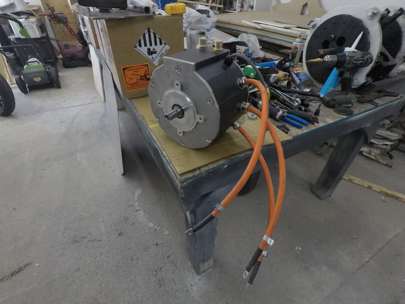
The differential has a 16T drive pinion and a 41T drive gear = a gear ratio of 2.56:1. I'm using a 12T drive sprocket with a 7/8" keyed weld-on hub on the 55 kW ME1616 motor and linking it to a 18T sprocket with a 1-1/4" keyed weld-on hub connected to a keyed stainless steel shaft that I welded another hub and plate to which was bolted to the diff's output shaft. Total sprocket ratio is 3.84:1. The sprockets are driven by a 530 o-ring chain. The motor is mounted to a plate with elongated bolt holes and a piece of 90° angle welded to the top, which a 1/2"-13 threaded rod is fastened to and serves as part of the chain tensioner.
With the 22" wheels and a max motor rpm of 6000 (~1500 at the wheels), the top speed should be around 160 km/h (~100 mph). The motor is capable of 0.33 nm (0.24 ft-lb) of constant torque per amp which amounts to around 82 nm (60 ft-lb) continuous or ~180 nm (132 ft-lb) at peak power at the motor shaft, so the gearing should bump it up to close to 316 nm (233 ft-lb) continuous, 700 nm (500 ft-lb) peak at the wheels.
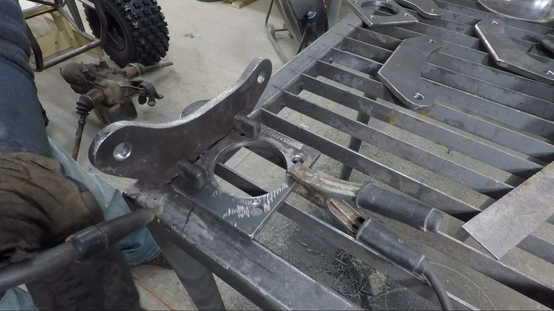
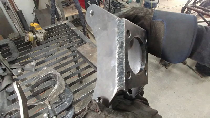
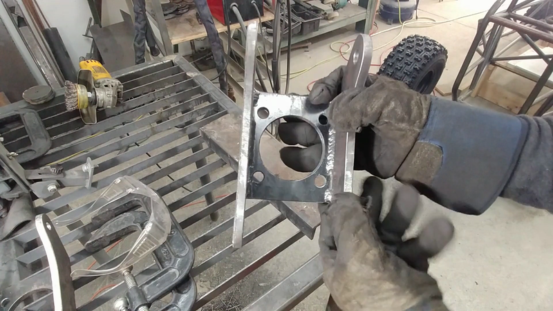
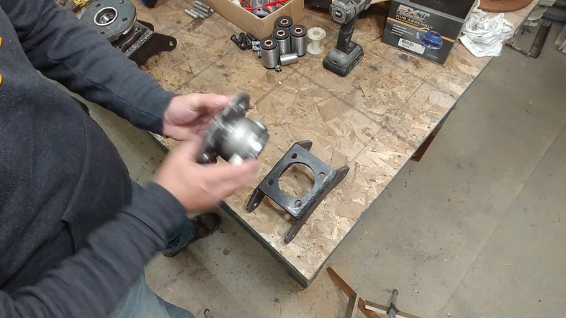
The rear brakes, again from a Yamaha Banshee, will be mounted in front of the motor instead of the axles, and will consist of one large rotor with two hydraulic calipers, both of which have a spring loaded mechanical parking/emergency brake feature that will be connected to a cable and lever in the cockpit.
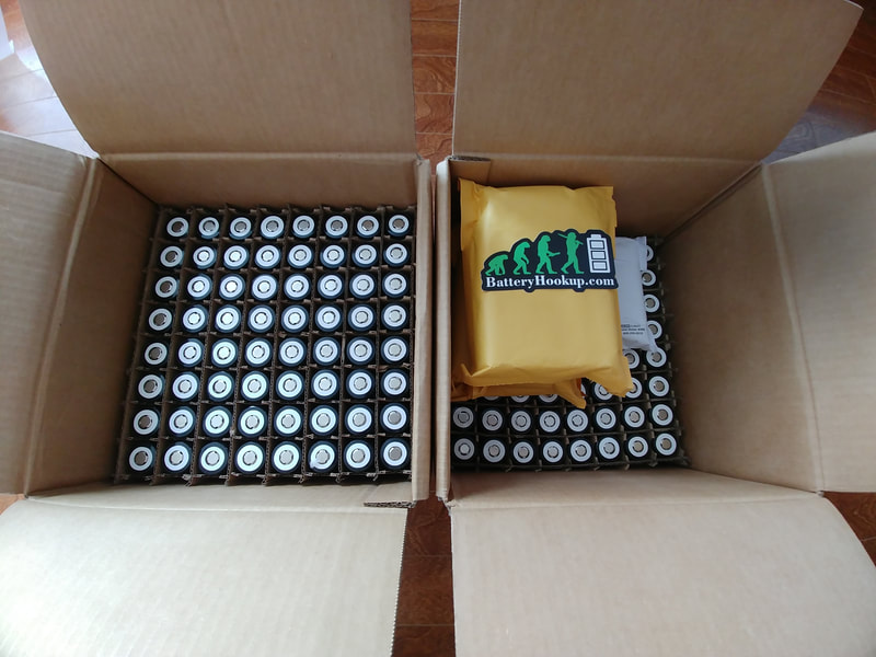
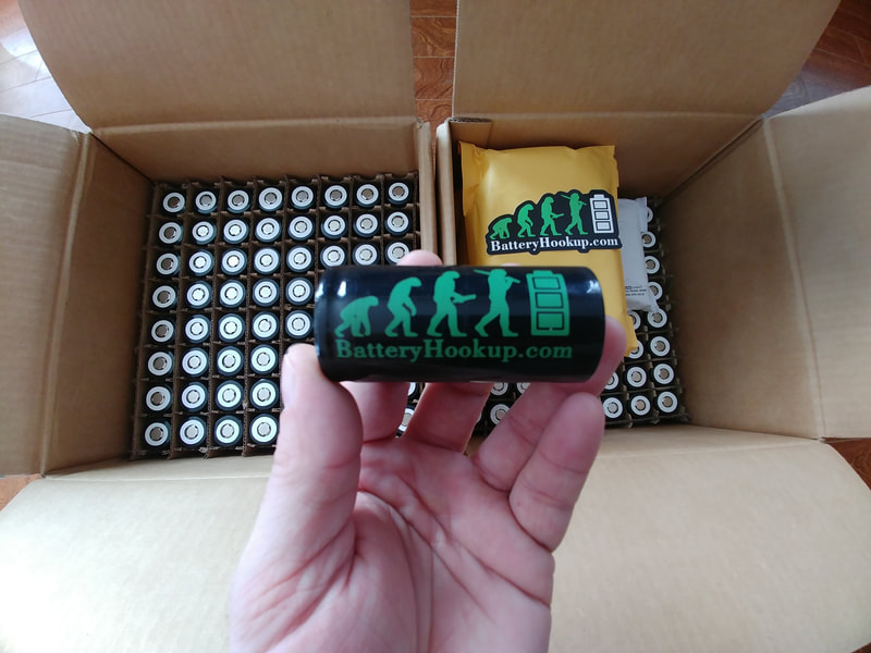
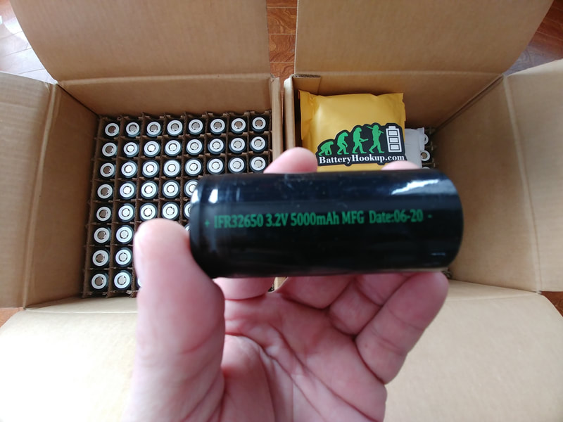
I've decided to make the battery a bit smaller than originally planned, to save some space and weight. Instead of a 24P32S pack of the 5000mAh LiFePo4 cells from batteryhookup.com for 11.5 kWh @ 96V, I'm building a 20P32S pack for 9.6 kWh @ 96V.
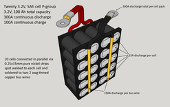
I'll connect 20 of the 3.2V, 5Ah batteryhookup cells in parallel to form a larger 3.2V, 100Ah cell or 'p-group' using 0.25x15mm nickel strips and 2 awg copper bus wire; the nickel strips will be soldered directly to two bus wires on each side of the pack first to avoid overheating the cells, then the strips will be spot welded to each cell. The purpose of the bus wires is to eliminate the need to spot weld 4 or 5 layers of nickel strips for the series connections, which would add more work and force me to make the battery in one or two large and awkward to handle blocks. Instead, I'll be able to install the battery into the crosskart one p-group at a time, and easily connect/disconnect them with a couple of wrenches.
I had considered using tinned copper busbars, but they're way too expensive. Tinned wire is cheaper. Aluminum busbars would be another more affordable option if it were possible to solder or spot weld the nickel to it successfully, but most attempts by others in the past have had subpar results if not complete fails. The nickel strips could be connected to the aluminum using screws and large flat washers, but having current flowing through the screws and the crosskart being bumped around in the trails might cause them to vibrate and work lose over time and I didn't want to have to tear open the packs to inspect them on a periodic basis.
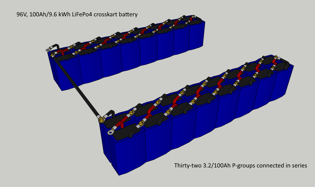
The p-groups will be wrapped in some thin vinyl or abs sheets and sealed with PVC heat shrink tubing. Once I have 32 of them made, they'll be connected in series with brass nuts and bolts and tinned copper lugs to form the 96V, 100Ah battery.
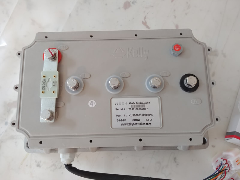
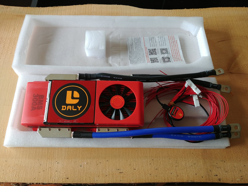
The bank will be connected to a 300A, 32S Daly BMS to keep the cells balanced and help protect the battery from overcharging/discharging. To control the motor, I'm using a KLS96601-8080IPS sinusoidal wave controller from kellycontroller.com. They actually sold me the motor and controller as a kit by request; they don't advertise the ME1616 on their website but they can provide it or any other Motenergy motor for you. Contact Fany at sales@kellycontroller.com for more information.
The controller is fully programmable, so everything from throttle response to speed to discharge and regen braking current can be adjusted via a PC or bluetooth and Android smartphone. Kelly makes reliable motor controllers, I've used them in almost all of my projects.
2 Comments
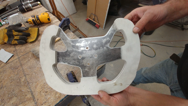
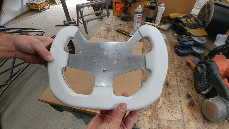
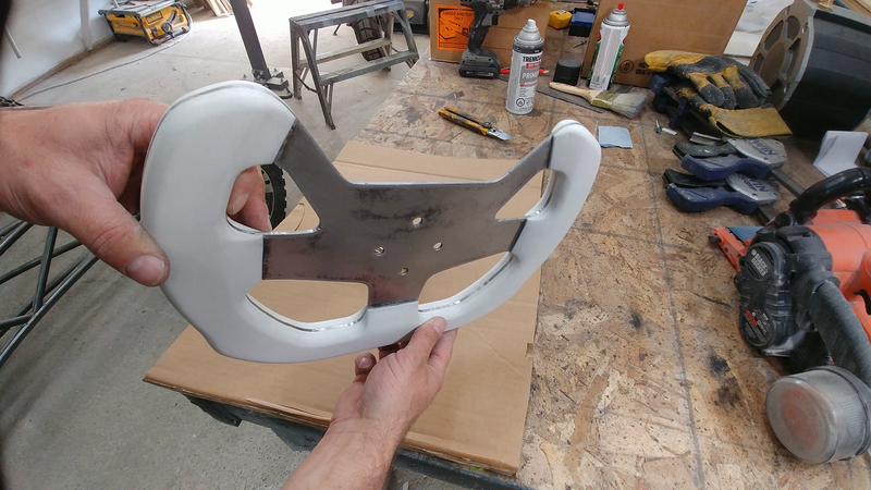
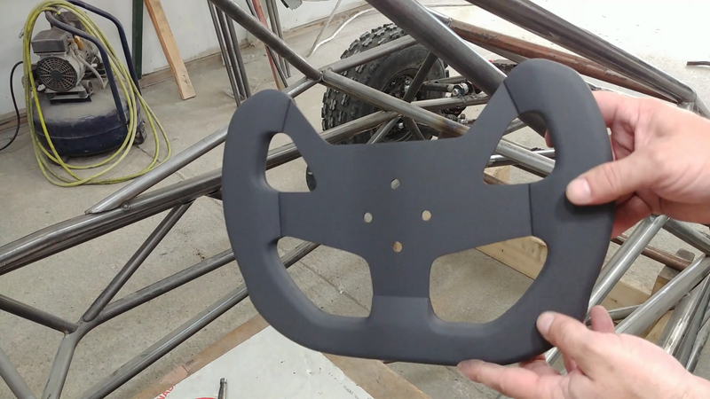
In this video I make a custom steering wheel for my electric crosskart buggy using 1/8" steel plate, 1/2" PVC foam board, and PL400 adhesive.
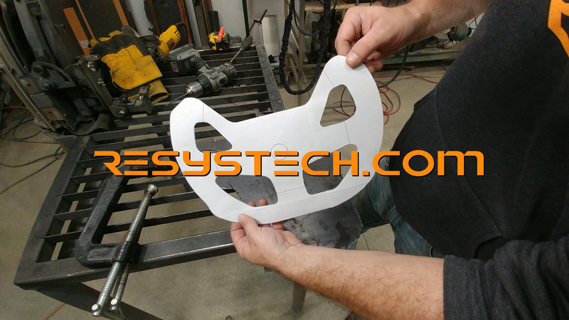
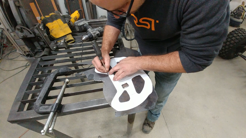
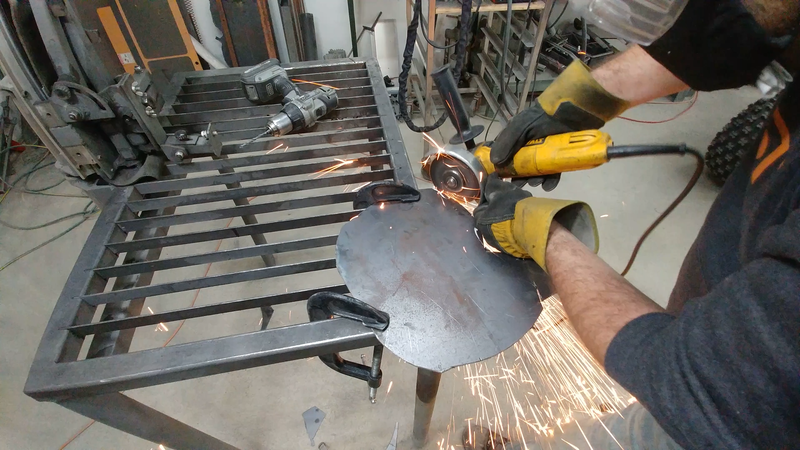
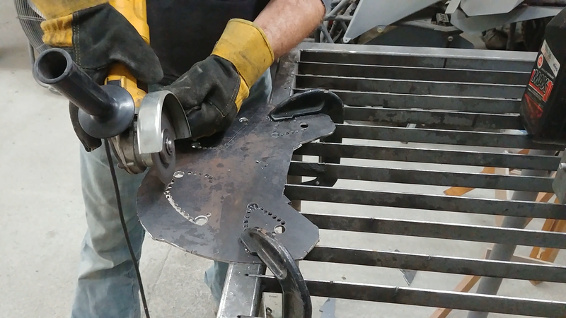
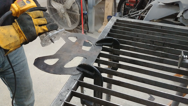
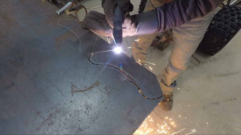
Why not just buy one? They're EXPENSIVE for something so simple. I wanted an open top, flat bottom steering wheel to give more leg room and an unobstructed view through the windshield. So I picked a design that I liked online, downloaded a jpg and scaled it to the size to create a template. I used a scratch awl to trace the outline of the template onto a sheet of 1/8" mild steel plate, then cut the perimeter with an angle grinder and cutting wheel.
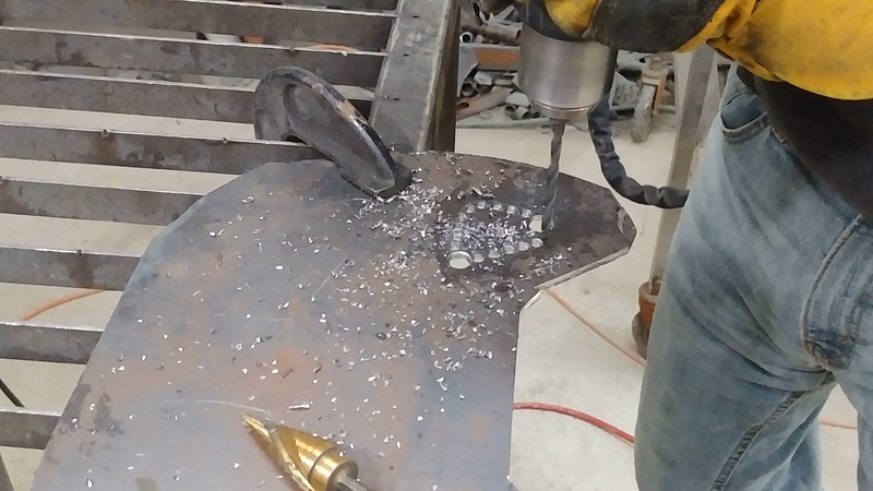
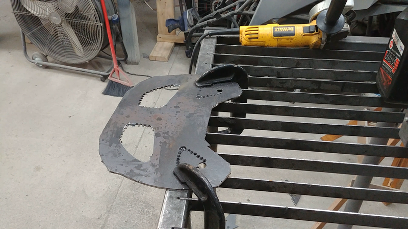
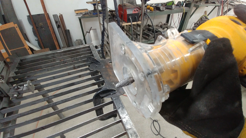
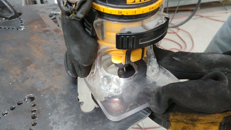
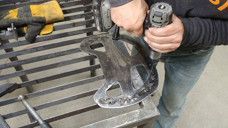
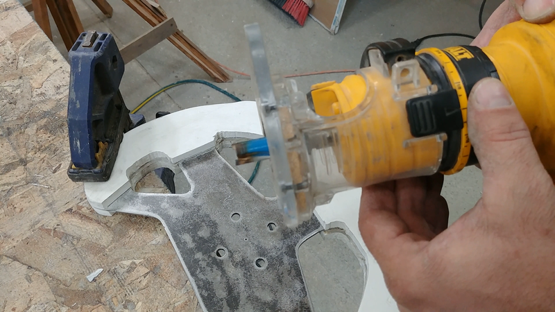
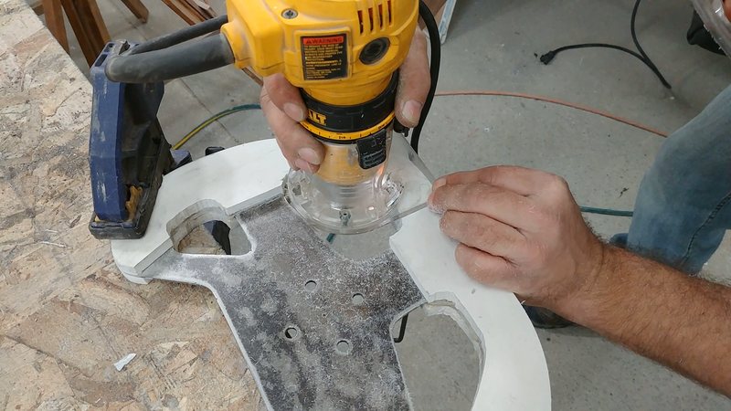
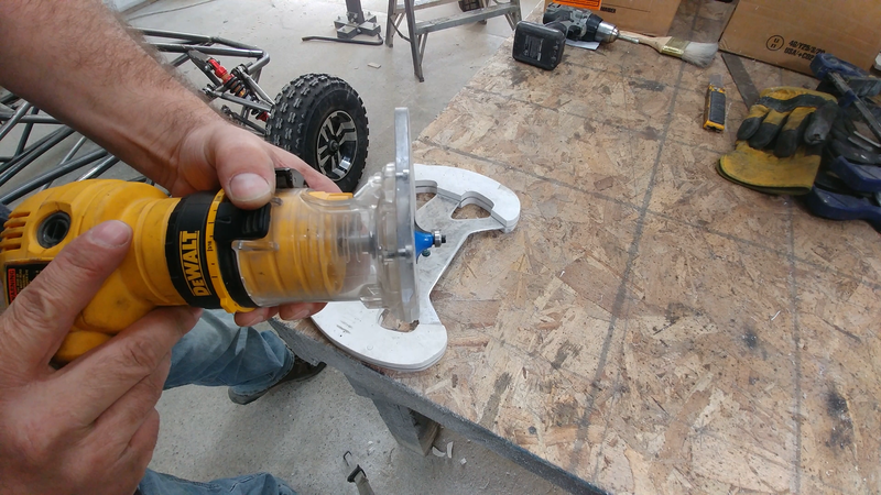
The cutting wheel on the grinder is less than ideal for cutting the holes for the grip. One option is to use a jigsaw with a metal cutting blade. I was concerned that the blade might jam up and distort the sheet metal as they sometimes do, so I decided to drill a series of small holes and cut out the majority of the waste with the angle grinder, then used a carbide burr bit in my trim router to clean the edges to the line. The burr bit is technically for a die grinder (a pneumatic Dremel type tool), but my compressor's tank capacity isn't large enough to keep up with it. But the bit and the trim router are rated for the same speed, so it worked just fine. A straight carbide router bit would also work, as I demonstrate later in the video when doing the final trimming.
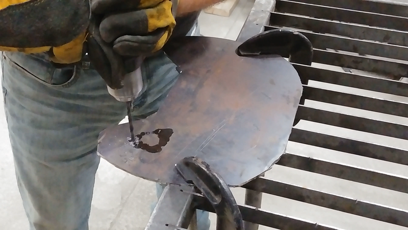
I then used a flap disc sander on the angle grinder to remove the mill scale from the sheet metal and rough up the surface, then drilled another series of holes around the perimeter of the steering wheel.
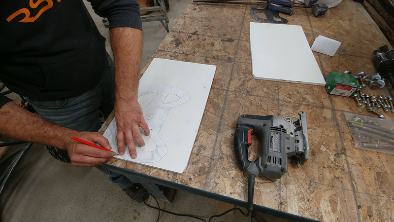
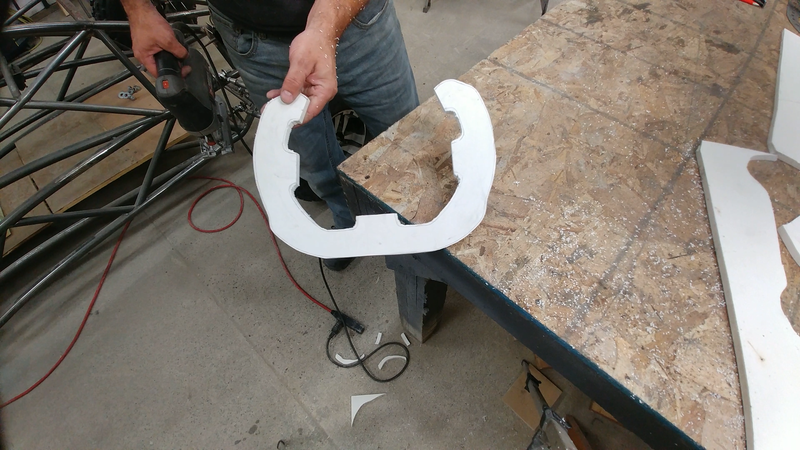
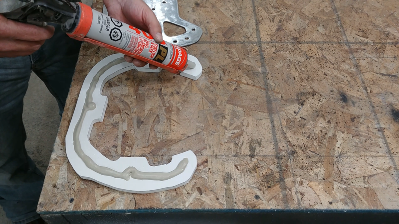
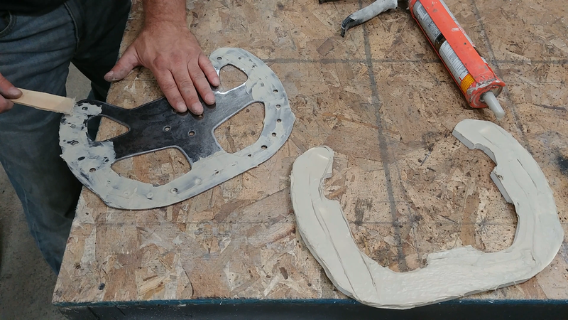
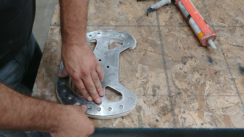
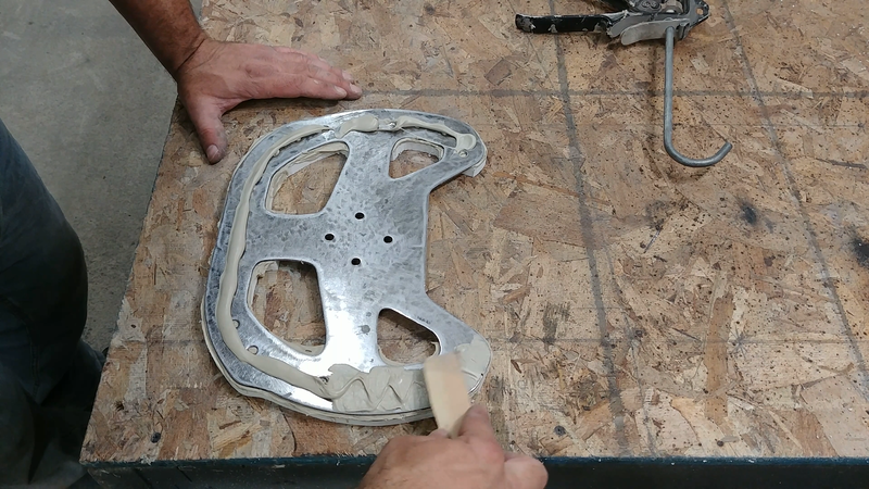
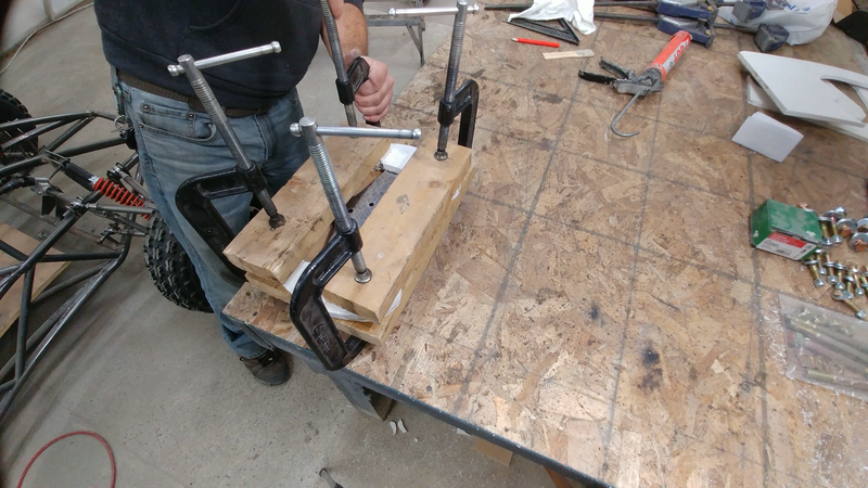
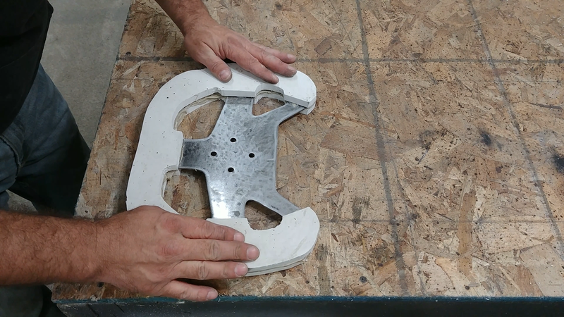
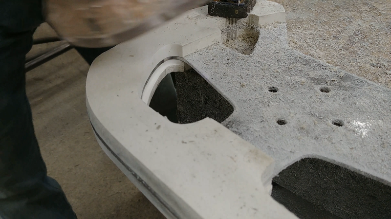
I traced the template onto a piece of 1/2" PVC foam and cut two profiles of the steering wheel from it with a jigsaw, then roughed up the faces with sand paper and cleaned them of debris. These will form the actual grip for the steering wheel. I applied a layer of PL400 adhesive to one side of one PVC piece and to the corresponding side of the sheet metal 'frame', then pressed them together until the adhesive oozed from the sides and through the holes drilled into the frame. Then I applied another layer of PL400 onto the other faces of the frame and PVC and sandwiched the laminations together using clamps, and left it overnight to cure.
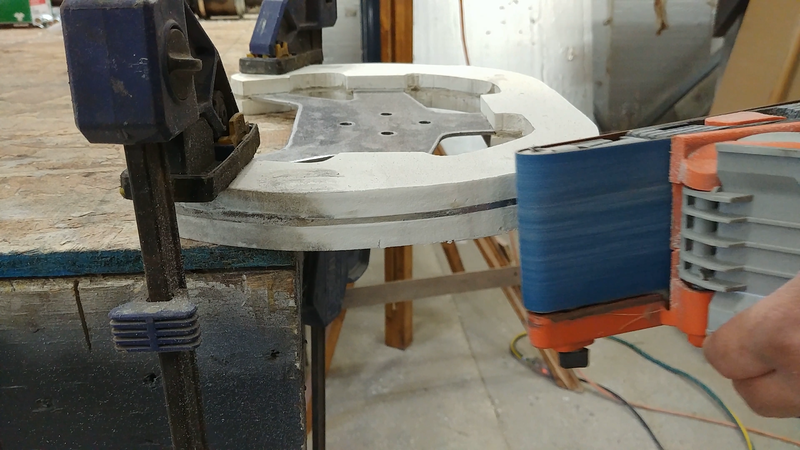
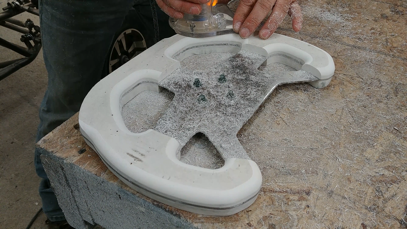
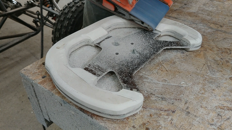
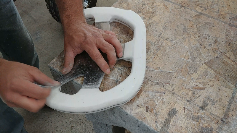
The next day, I cleaned up the edges of the steering wheel and started forming the grip with a belt sander. Using the trim router with a straight carbide router bit set to just half the thickness of the steering wheel, I flushed up one side of the PVC with the steel frame. Then I used a flush trim bit to perfectly trim the other side to the first. A round over bit finished all of the PVC edges so the steering wheel is comfortable to grip.
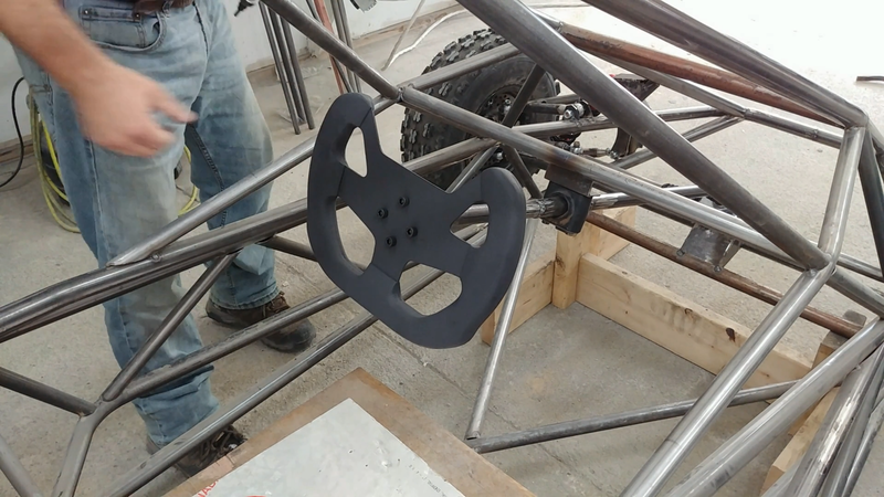
After a bit of hand sanding with some fine sandpaper, I painted the steering wheel matte black. I would have preferred to use black PVC instead of painting it, but I already had some white PVC scraps that I wanted to use up. Another more affordable option for the grip could have been wood with a strong polyurethane finish.
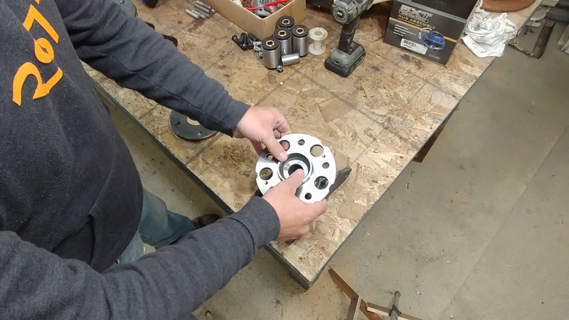
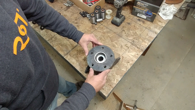
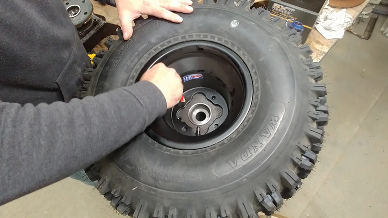
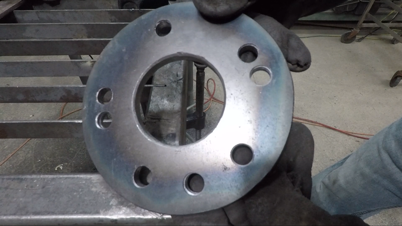
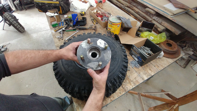
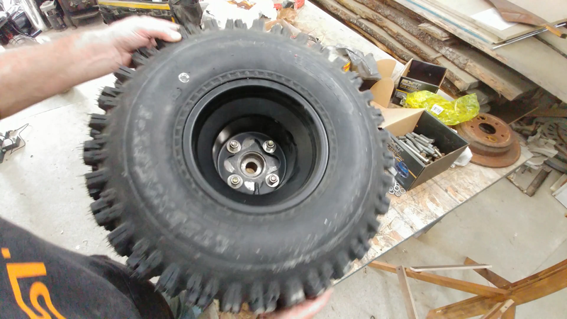
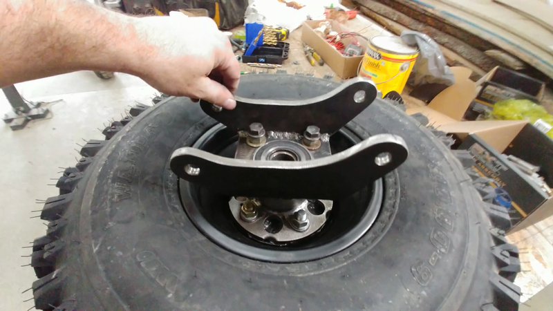
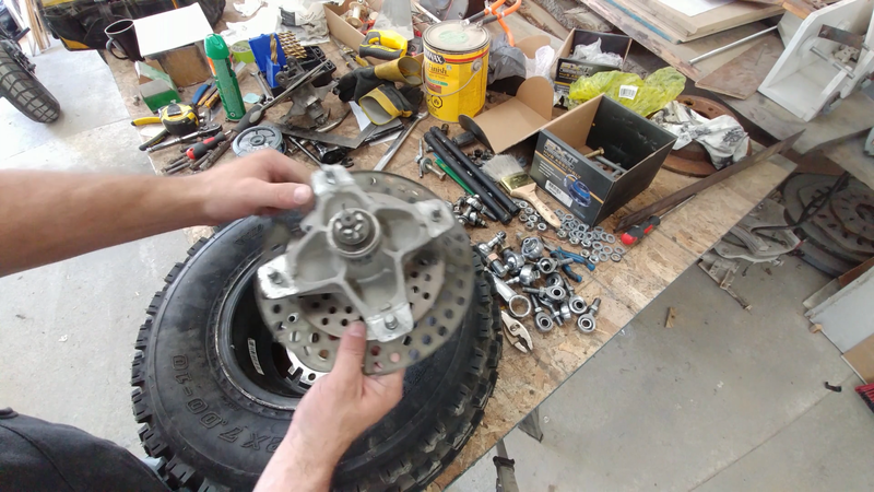
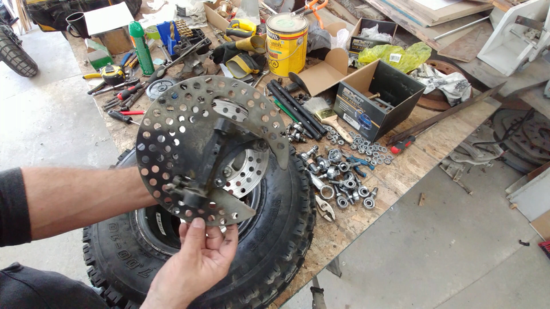
I began this stage of the build by fabricating some custom rear axle housings out of 3/8" steel plate to couple with the Honda CR-V wheel hubs/bearings and axles that will be installed later. I'm using these because I've chosen to install a CR-V rear differential as well (fitted with a limited slip conversion kit), so the drive components need to match up. Unfortunately, the CR-V wheel hubs are 5 bolt and don't match up with the 4 bolt 9" atv wheels that I'm using, so I had to make hub adapters to bolt up with them. The wheel hubs fit perfectly inside the wheel rims, so I used the bolt holes in the rims as a pattern to trace their location onto the new hub adapters and drilled them out.
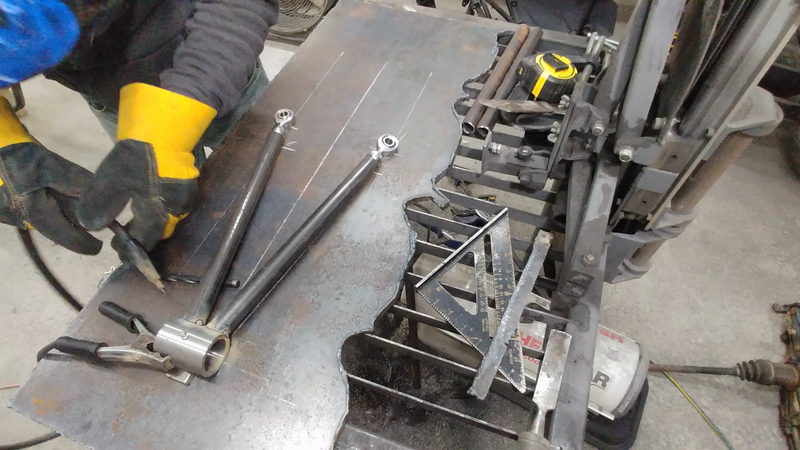
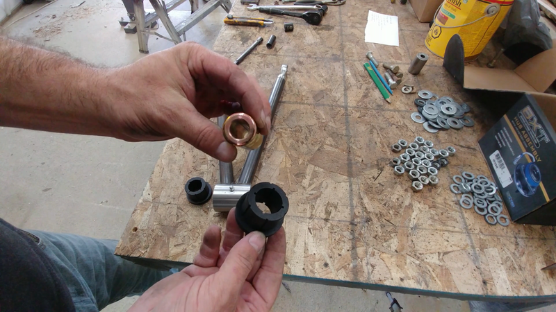
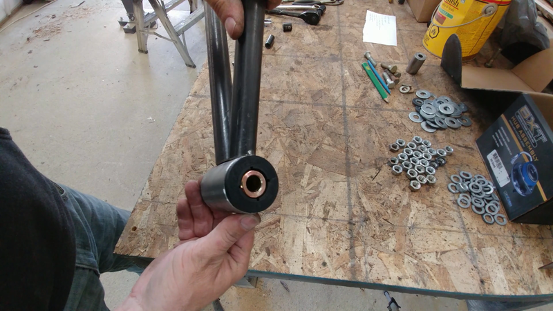
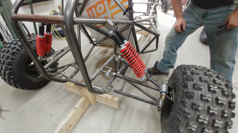
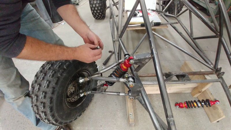
After the rear axle housings and detachable hub adapters were made, I then built the control arms for the rear double wishbone suspension using 1"x0.12" DOM tubing. These were designed with a specific geometry that will adjust the camber of the wheels when the shocks are compressed to increase anti-roll stability. I used 1/2" heavy duty heim joints to connect the arm ends to their mounts on the chassis, and weld-on polyurethane/steel bushings to connect the arms to the axle housings. Two 14" 400 lbs coil-over shocks where then fitted to each side.
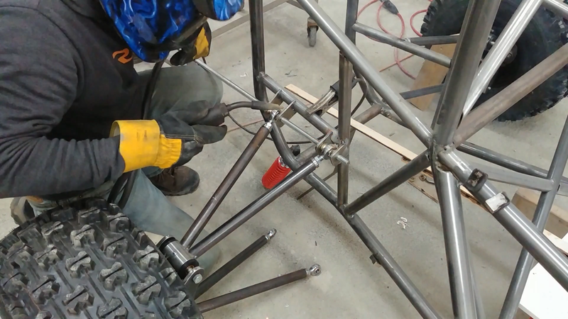
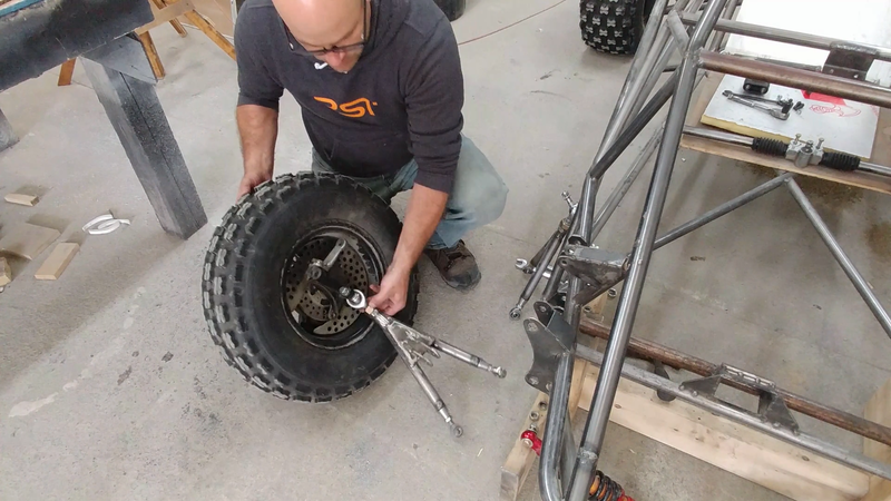
The front suspension was tackled next. The front of the chassis is low and wide so the control arms needed to be quite a bit shorter, and I had to be careful to allow enough room for the 11" 800 lb shocks to travel between the upper arms because they needed to be mounted to the lower arms due to the height constraint. I used heim joints to attach these arms to the chassis as well, but used ball joints to attach the arms to the steering knuckles, which were recycled from an old Yamaha Banshee atv.
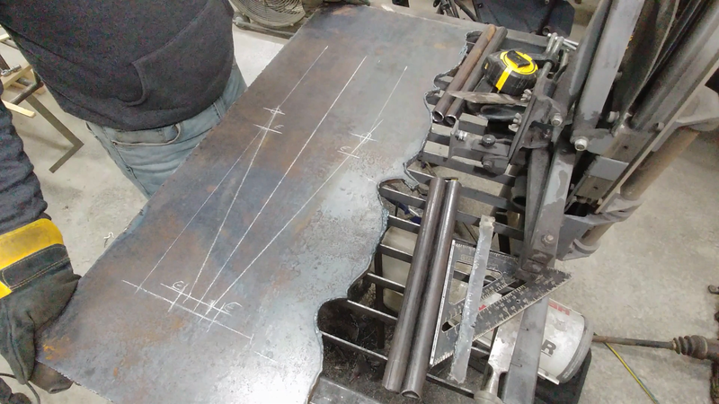
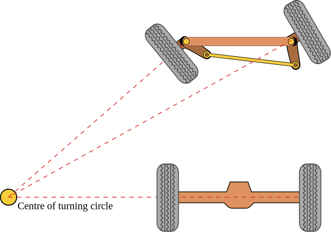
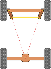
The only modification that I had to make to the knuckles was adjusting the angle of the steering arms relative to the rear axle to achieve proper Ackermann steering geometry. The steering arms need to point at the center of the rear axle to create a geometry that causes one wheel to turn more than the other when cornering. This compensates for the different turn radii that each wheel travels around a corner; the outside wheel will travel around a large radius than the inside wheel, so the angle of the outside wheel should be less than the inside wheel to minimize tire wear. Because the crosskart has a longer wheelbase than the Banshee that the steering knuckles came from, the Ackermann geometry would have been off if the arms weren't adjusted accordingly.
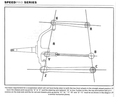
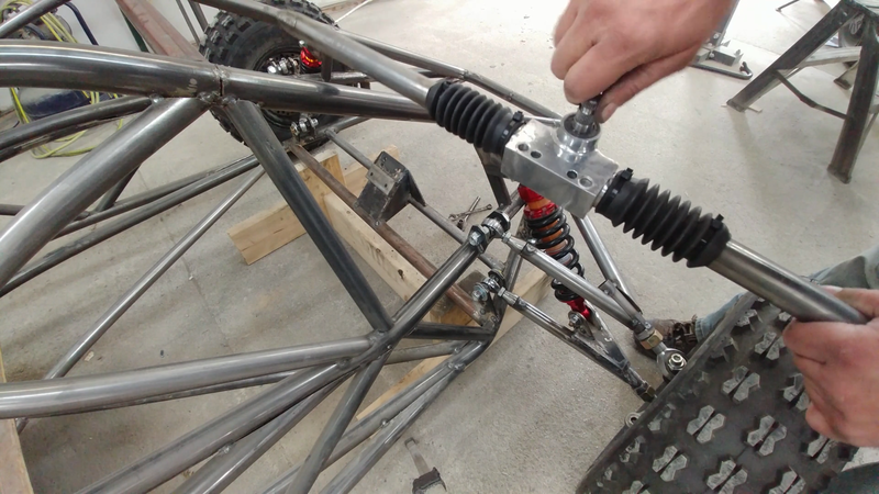
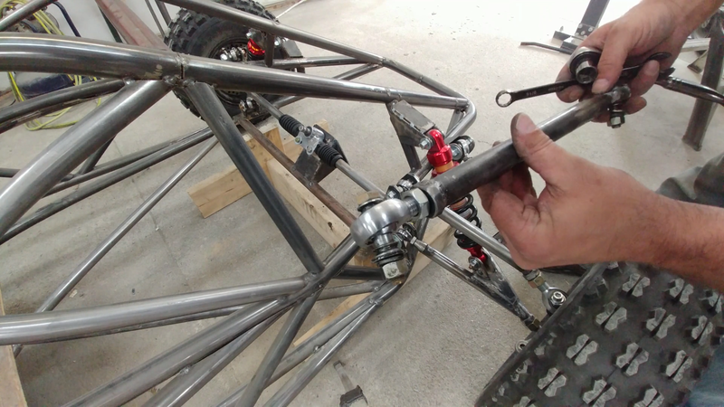
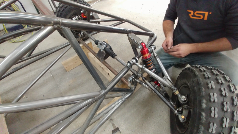
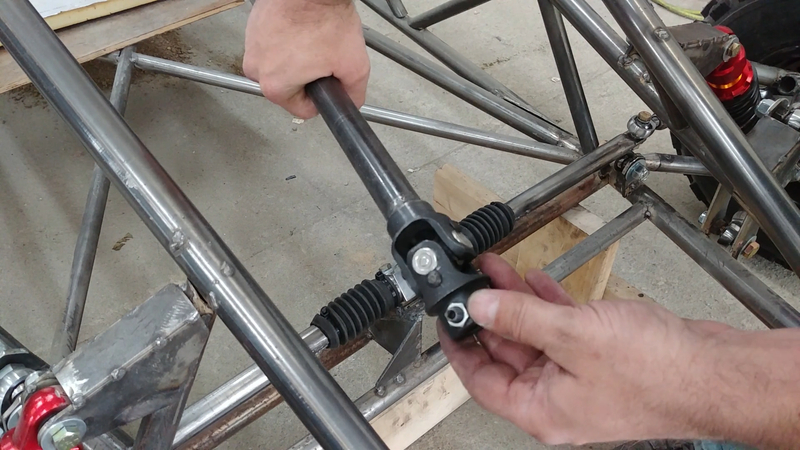
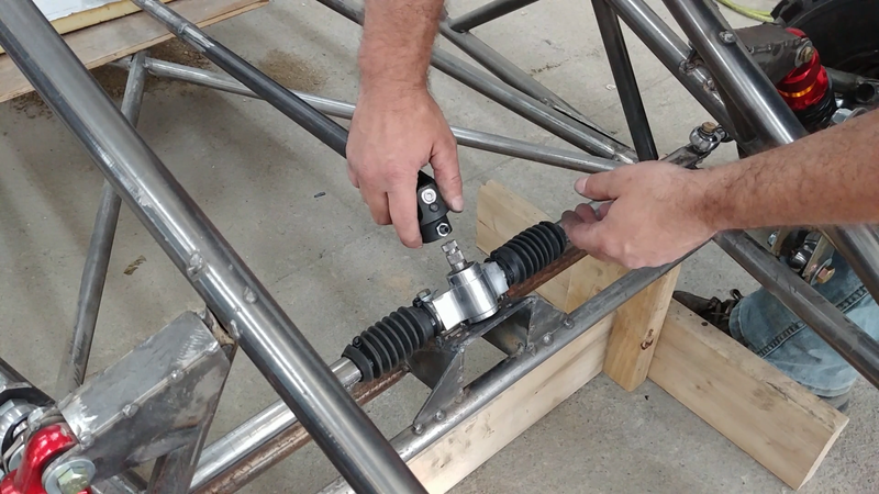
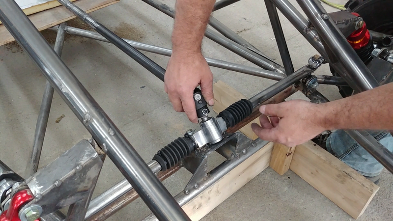
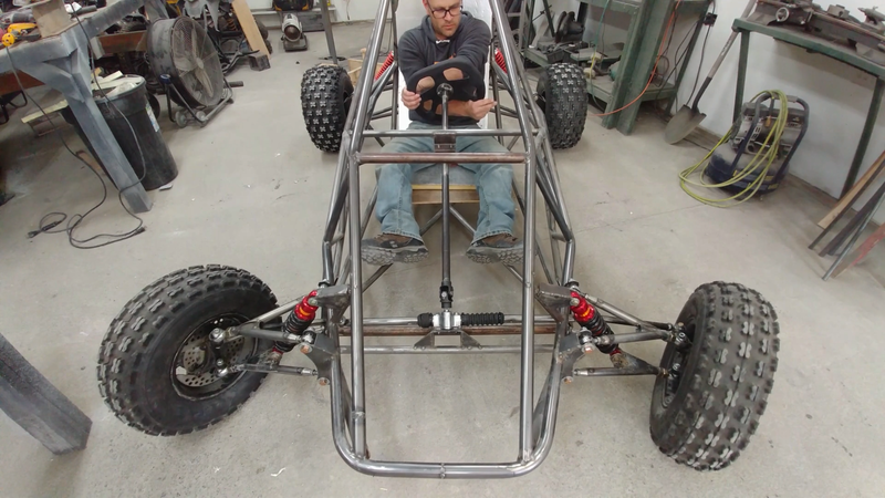
I then installed the steering rack, column, and tie rods. The tie rods are positioned at a certain height and angle relative to the control arms to minimize bump steer. Bump steer is the tendency of the tie rods to push or pull on the steering knuckle when the suspension is travelling up or down, causing the wheels to turn (or toe out) slightly, which affects handling and tire wear. If a tie rod or tie rod end is too high, too low, too short or too long for the suspension geometry, then bump steer will be increased. Simply put, to minimize or eliminate the effect, the control arm and tie rods need to be parallel with each other, and the chassis pick-up points and rod ends need to line up as the image below shows.
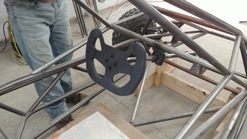
I then made a custom steering wheel. It's currently bolted to the column, but I'm going to add a quick release mechanism before painting to easily remove the steering wheel when I need to get in and out of the kart. You can check out how I made the custom steering wheel in the next post.
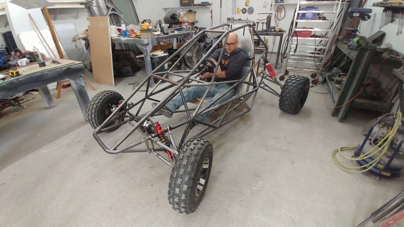
In this video I begin building the 55 kw off road electric crosskart buggy. Crosskarts are basically large, powerful off road go-karts built for racing on dirt and snow/ice tracks. I won't be racing this machine, so it's being built with more aggressive tires and a higher than normal ground clearance for ripping around in the trails.
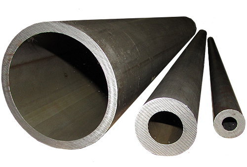
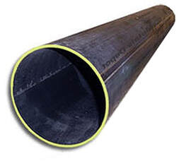
The chassis is made with 1.25" and 1" diameter x 0.12" thick wall DOM steel tubing. It can also be made with the same size HREW tubing, which is similar to DOM in dimension but has a welded seam and is more affordable. DOM is basically welded tubing like HREW that's been worked over a mandrel and ground and polished to precision inside and out so there's no welded seam to deal with when it's finished. DOM is slightly stronger than HREW, but not necessarily required for chassis building unless race regulations call for it.
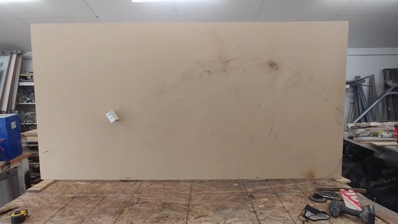
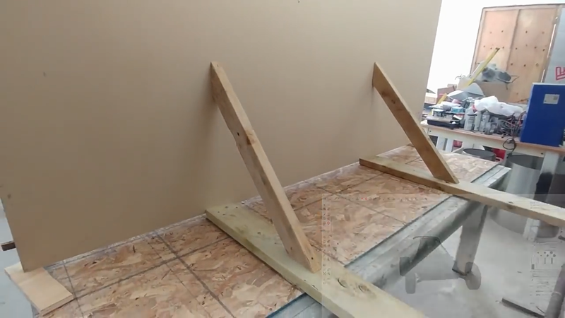
I first begin the build by laying out the bottom and side profiles of the chassis on a level workbench and a sheet of MDF that was attached at a right angle to the bench with 2x4 wood braces and screws. The reference lines drawn represent the center of the tubing, and make it easier to measure, mark, and fit each piece. The chassis was built in two halves that were later joined with crossmembers.
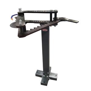
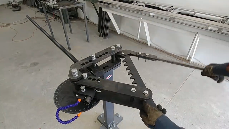
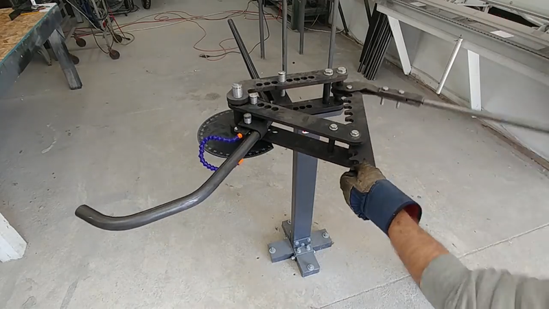
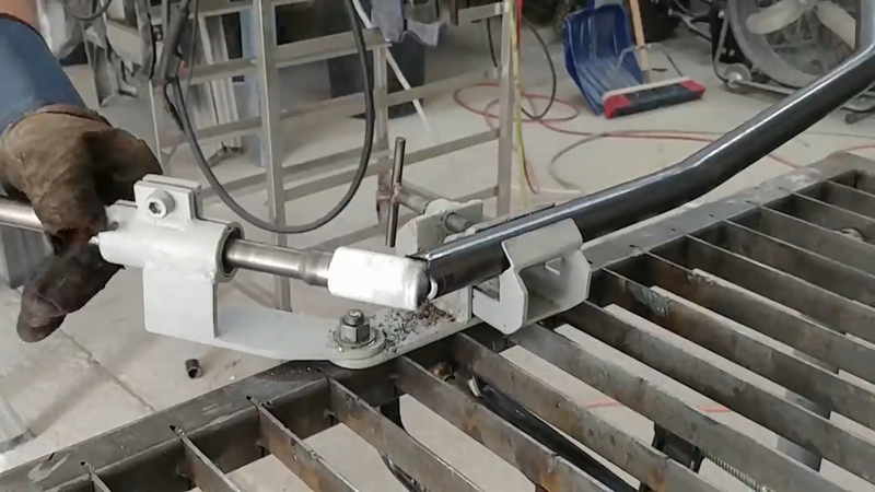
I used my TB-3 rotary draw bender from Kaka Industrial to bend the tubing. It's a bit pricy for a manual tool and might be a bit too much for the avg DIY'er to invest in, but if you're into this kind of stuff and plan on building more than one tube chassis in the future, then forget about miters - this is the tool for you. It works great, and I'm really happy to have it in the shop. This bender saved me a lot of work.
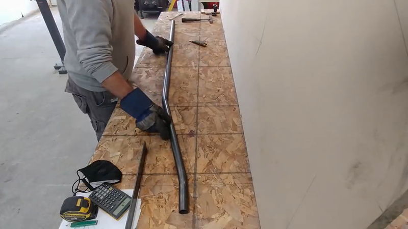
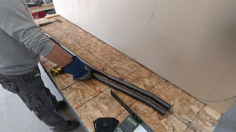
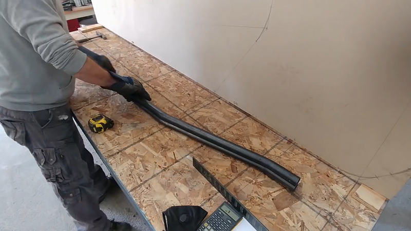
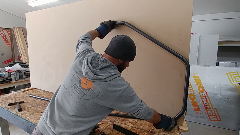
To avoid making mistakes, I bent each piece for both sides of the chassis and placed them next to each other on the layout lines to ensure they match in length, bend angle, etc.
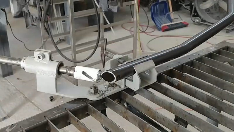
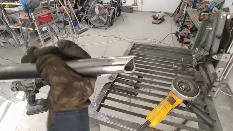
When necessary, I used my DIY tube notcher to notch the ends of the tubing where it needs to marry with another piece. The tube notcher saves a lot of work compared to using an angle grinder and it makes clean cuts that fit tightly with no gaps to save more time and $ when welding later. When I was satisfied with the fitment of each piece, they were tack welded in place.
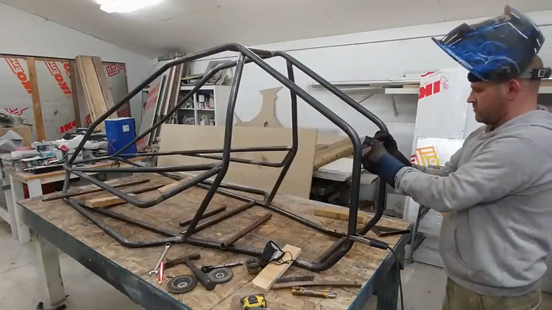
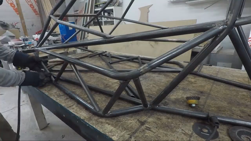
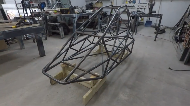
When the two halves of the chassis were finished, I removed the upright plywood from the bench and set up the halves so they were lined up with each other and spaced the right distance apart, then cut and welded the crossmembers between them. When the crossmembers were in place, I moved on to the diagonal bracing. The bracing went in the bottom, sides and back of the chassis. Its purpose is to form a truss assembly in these areas so they can support a load at any point and transfer it to the suspension, similar to how the roof trusses in a home are designed to carry and transfer a snow load from the middle of the roof toward the exterior load bearing walls.
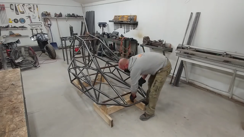
Once the halves were joined and the bracing was installed, I built a couple of wooden stands to set the chassis on at the desired (unloaded) ride height to prep for the suspension build. You can read more about that in the next post.
|
AuthorJames Biggar Archives
March 2023
Categories |


 RSS Feed