|
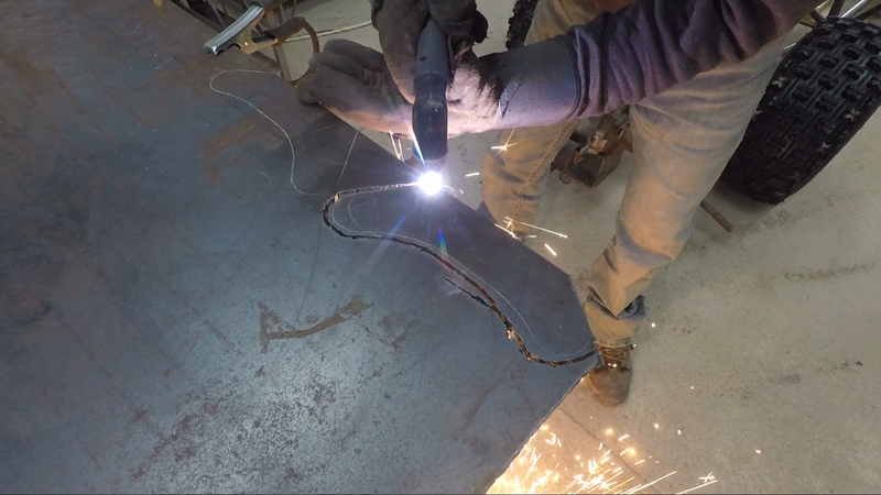
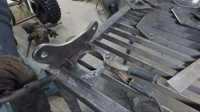
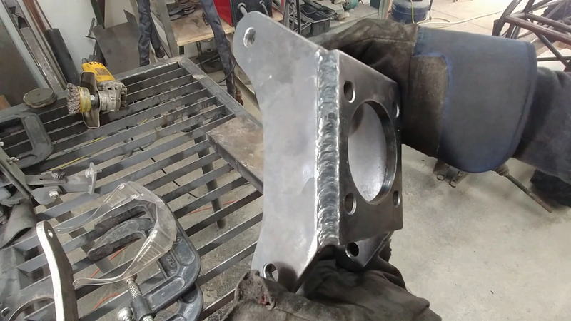
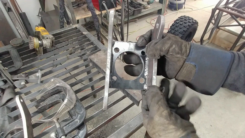
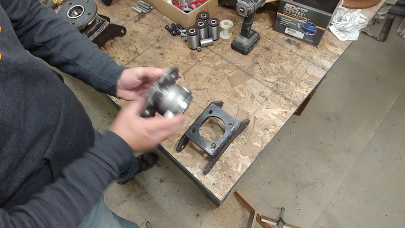
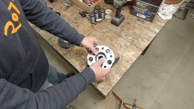
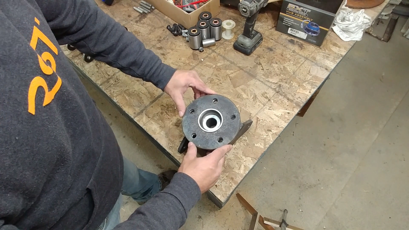
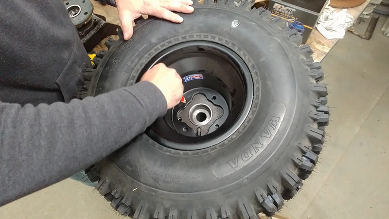
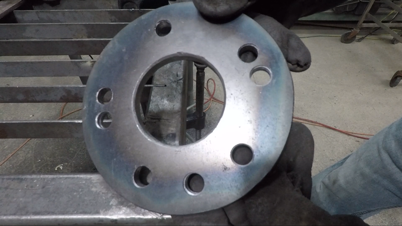
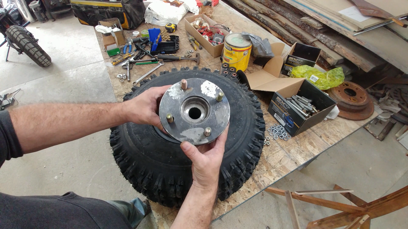
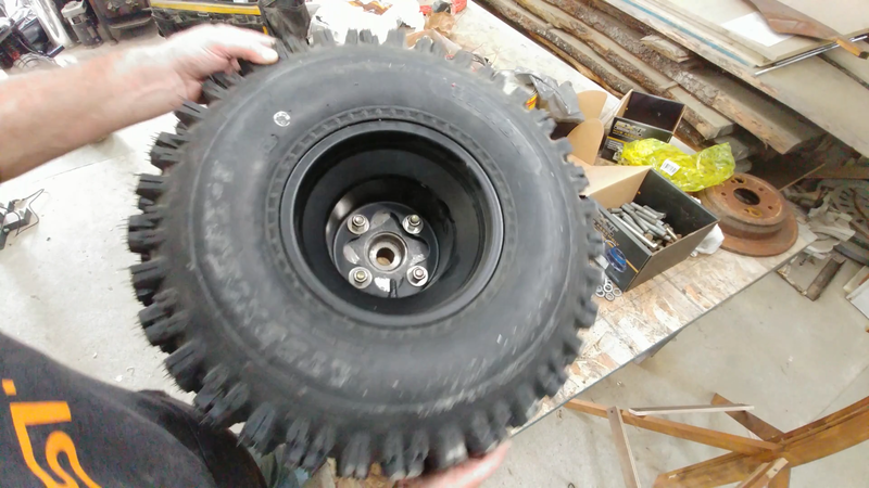
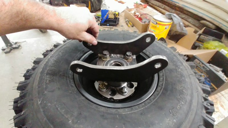
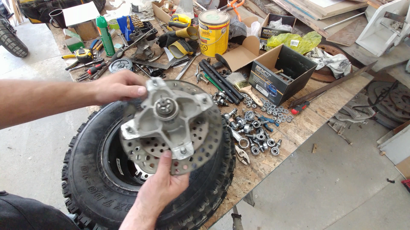
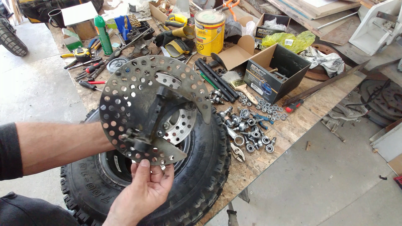
I began this stage of the build by fabricating some custom rear axle housings out of 3/8" steel plate to couple with the Honda CR-V wheel hubs/bearings and axles that will be installed later. I'm using these because I've chosen to install a CR-V rear differential as well (fitted with a limited slip conversion kit), so the drive components need to match up. Unfortunately, the CR-V wheel hubs are 5 bolt and don't match up with the 4 bolt 9" atv wheels that I'm using, so I had to make hub adapters to bolt up with them. The wheel hubs fit perfectly inside the wheel rims, so I used the bolt holes in the rims as a pattern to trace their location onto the new hub adapters and drilled them out.
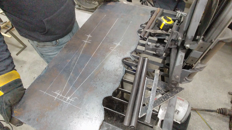
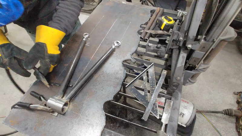
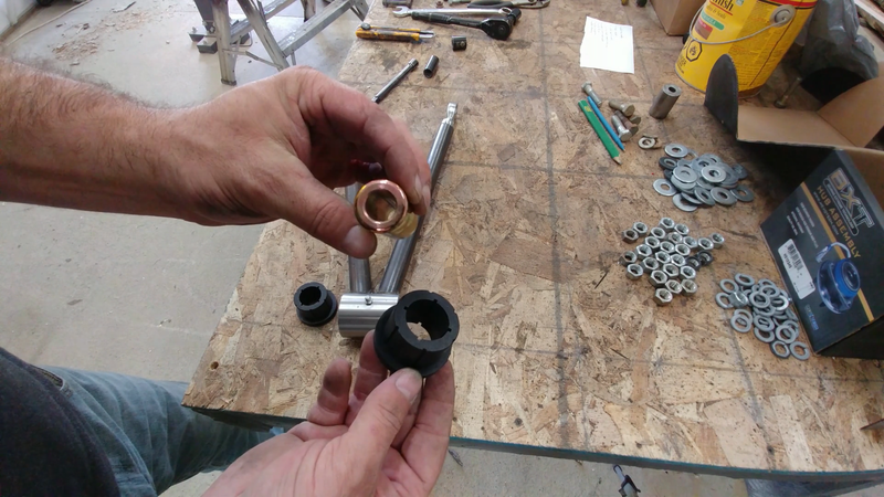
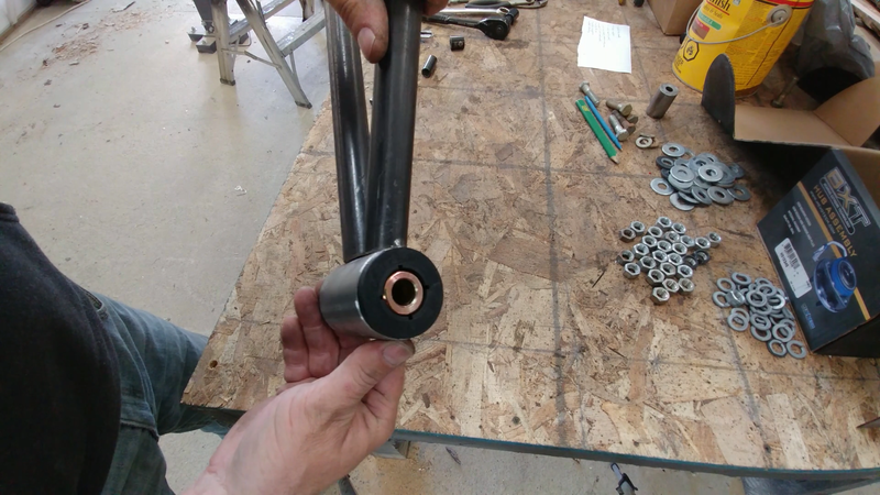
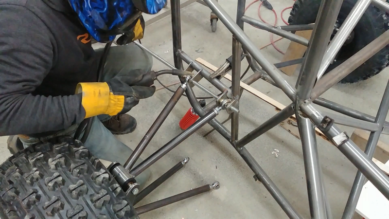
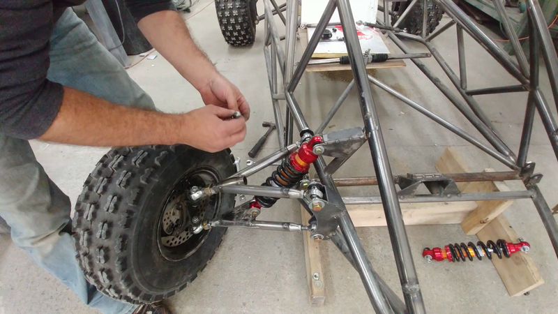
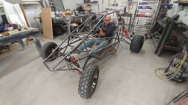
After the rear axle housings and detachable hub adapters were made, I then built the control arms for the rear double wishbone suspension using 1"x0.12" DOM tubing. These were designed with a specific geometry that will adjust the camber of the wheels when the shocks are compressed to increase anti-roll stability. I used 1/2" heavy duty heim joints to connect the arm ends to their mounts on the chassis, and weld-on polyurethane/steel bushings to connect the arms to the axle housings. Two 14" 400 lbs coil-over shocks where then fitted to each side.
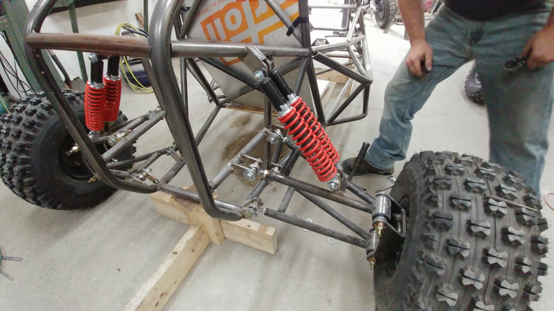
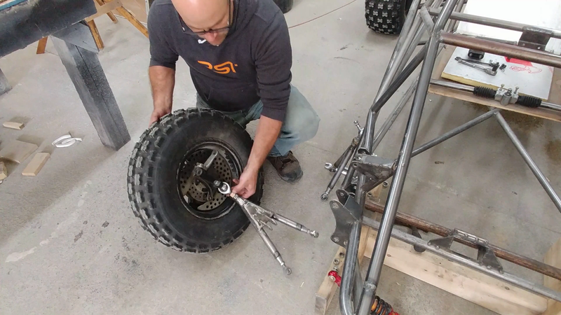
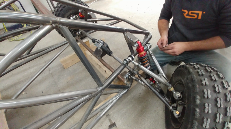
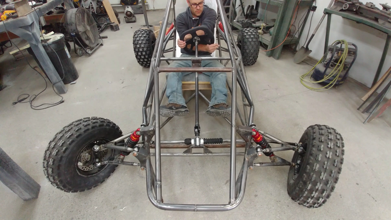
The front suspension was tackled next. The front of the chassis is low and wide so the control arms needed to be quite a bit shorter, and I had to be careful to allow enough room for the 11" 800 lb shocks to travel between the upper arms because they needed to be mounted to the lower arms due to the height constraint. I used heim joints to attach these arms to the chassis as well, but used ball joints to attach the arms to the steering knuckles, which were recycled from an old Yamaha Banshee atv.
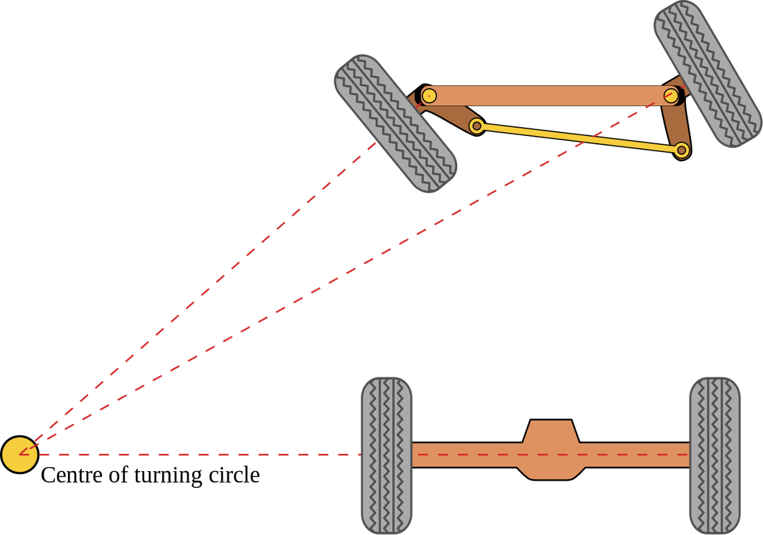
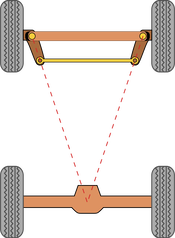
The only modification that I had to make to the knuckles was adjusting the angle of the steering arms relative to the rear axle to achieve proper Ackermann steering geometry. The steering arms need to point at the center of the rear axle to create a geometry that causes one wheel to turn more than the other when cornering. This compensates for the different turn radii that each wheel travels around a corner; the outside wheel will travel around a large radius than the inside wheel, so the angle of the outside wheel should be less than the inside wheel to minimize tire wear. Because the crosskart has a longer wheelbase than the Banshee that the steering knuckles came from, the Ackermann geometry would have been off if the arms weren't adjusted accordingly.
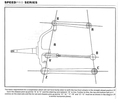
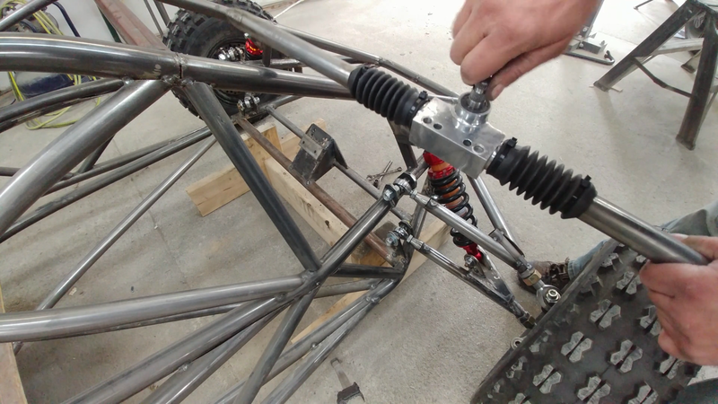
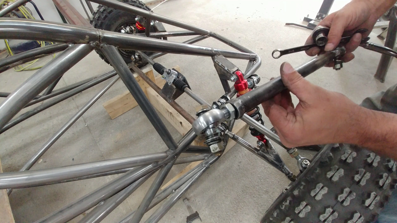
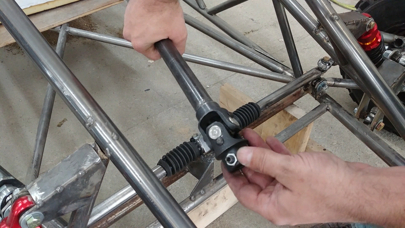
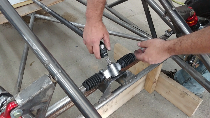
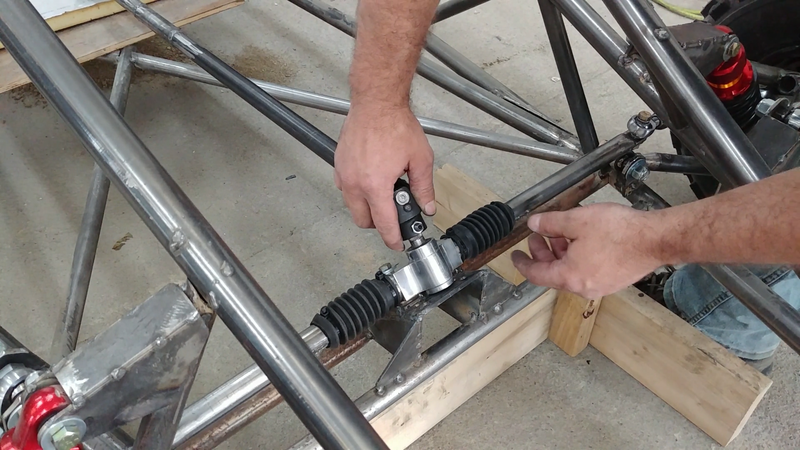
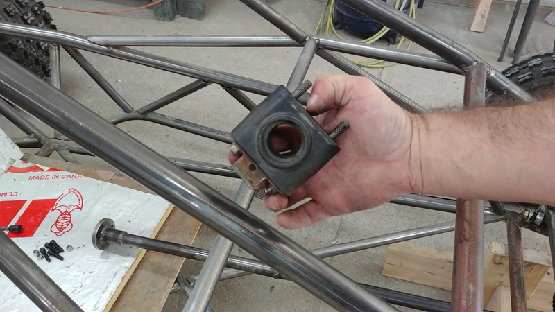
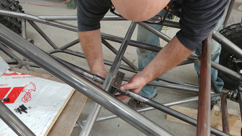
I then installed the steering rack, column, and tie rods. The tie rods are positioned at a certain height and angle relative to the control arms to minimize bump steer. Bump steer is the tendency of the tie rods to push or pull on the steering knuckle when the suspension is travelling up or down, causing the wheels to turn (or toe out) slightly, which affects handling and tire wear. If a tie rod or tie rod end is too high, too low, too short or too long for the suspension geometry, then bump steer will be increased. Simply put, to minimize or eliminate the effect, the control arm and tie rods need to be parallel with each other, and the chassis pick-up points and rod ends need to line up as the image below shows.
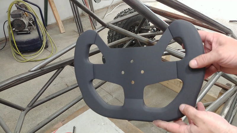
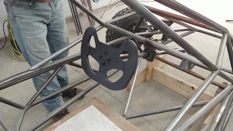
I then made a custom steering wheel. It's currently bolted to the column, but I'm going to add a quick release mechanism before painting to easily remove the steering wheel when I need to get in and out of the kart. You can check out how I made the custom steering wheel in the next post.
1 Comment
Moey
4/28/2022 02:24:48 pm
Hello, i was wondering if you may share or even sell me the plans. Id like to fabricate one
Reply
Leave a Reply. |
AuthorJames Biggar Archives
March 2023
Categories |

 RSS Feed