|
In this video I take a break from eating metal and abrasive dust in the workshop and make the battery modules for the electric crosskart project.
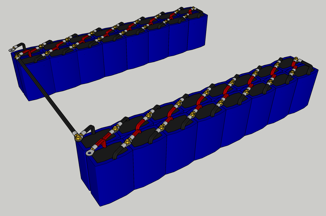
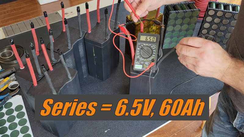
If you've been following the build from the beginning, you probably know that the original plan was to build the battery into the chassis' floor, like a typical EV. But I wanted a lower center of gravity and easier access to the battery for servicing, so I decided to split the battery into two packs that will be positioned on either side of the seat so that I can sit as low as possible without compromising ground clearance. The packs will each contain sixteen 3.2V, 120Ah LiFePo4 modules wired in series to produce 12.2 kWh at 102V nominal.
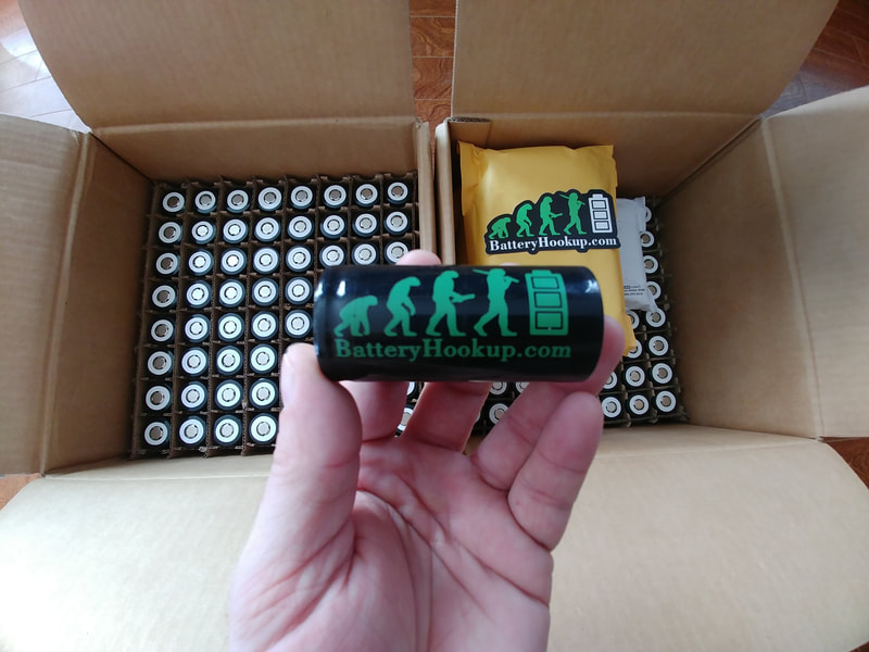
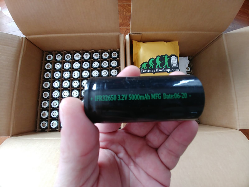
The modules are made up of twenty four 3.2V, 5000mAh 32650 LiFePo4 cells, all connected in parallel. The cells that I used were purchased from batteryhookup.com. I chose LFP (lithium iron phosphate) cells because next to LTO (lithium titanate oxide) they are the most stable lithium cells available, in that they won't explode and catch fire if there's damage or a short. The fact that batteryhookup.com is a domestic, family owned company with the best price online is another good reason why I chose these particular cells. They each have a continuous discharge current rating of 15A (3C, ie: 3 * amp hour capacity) and 50A peak (10C for approx. 10 seconds), and a continuous charge current rating of 5A (1C).
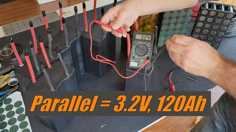
24 cells connected in parallel create a 3.2V module with 24 * 5Ah = 120Ah of capacity, 24 * 15A = 360A cont., 1200A peak discharge and 24 * 5 = 120A charge current capability.
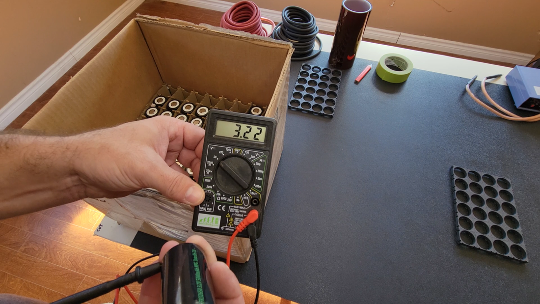
Before doing anything, I covered my work table with a sheet of ABS plastic to help prevent against accidental shorts while building the modules, and kept a pair of rubber gloves close by to wear when necessary. I then checked that the voltage of the cells were within 0.05V of each other. When cells of different voltages are connected in parallel, current will flow from the higher charged cell to the lower charged cell to equalize them, essentially turning them into one large cell. If the difference between any two cells is greater than 0.05V, then the rush of current after connecting them could be too great and cause damage to the cells or worse. 3.2V is nominal for LFP (lithium iron phosphate cells, or LiFePo4), so I used that as a benchmark and any cell that was between 3.2 and 3.25V. Cells that measured <3.2V were set aside and charged later to match.
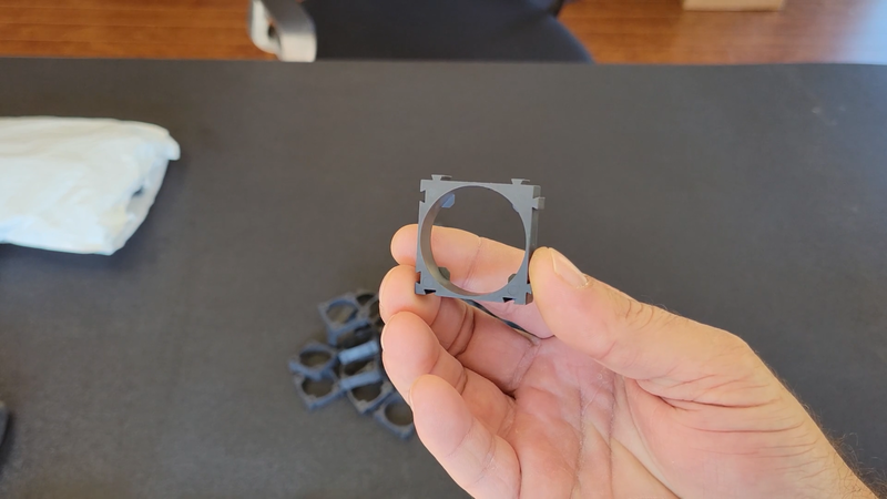
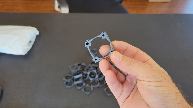
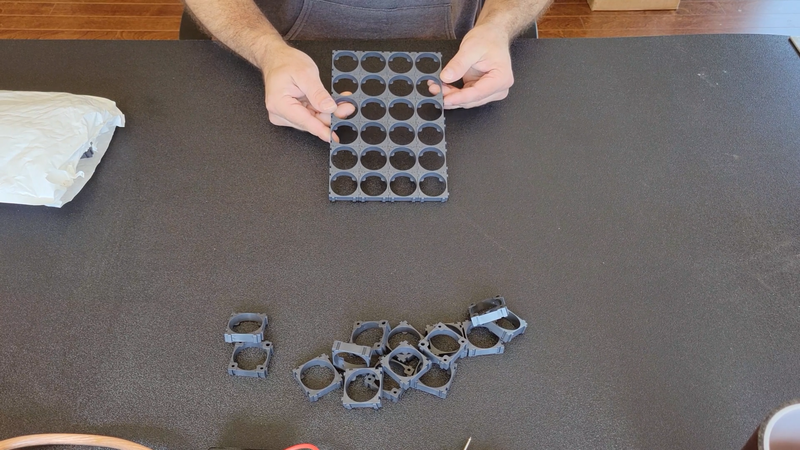
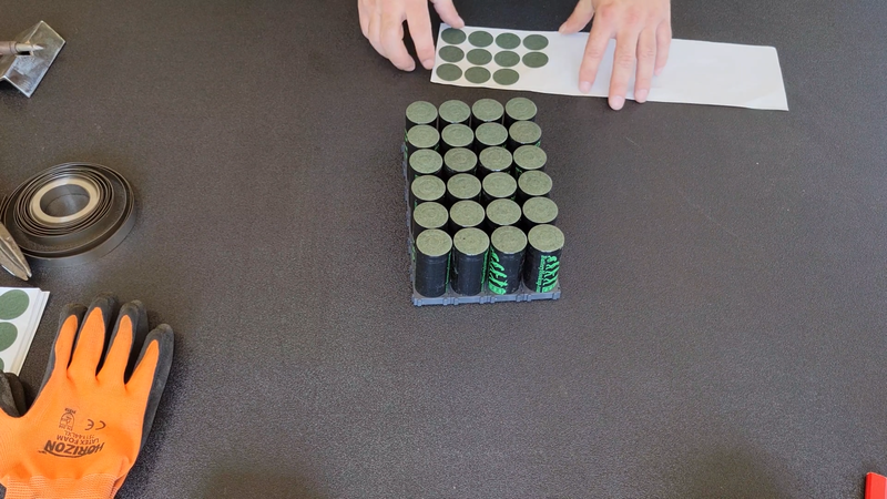
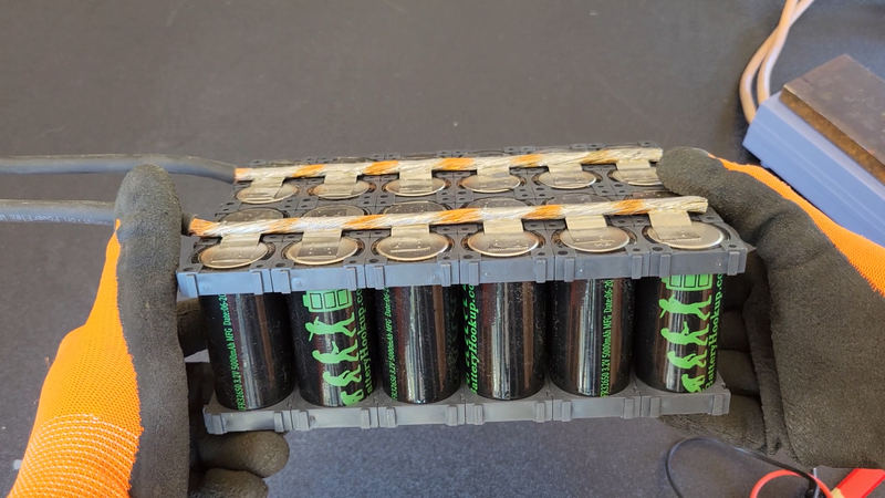
I used single 32650 cell holders from batteryhookup.com to assemble the cells into a 4x6 module configuration to suit the space constraints in the crosskart cabin. I had considered staggering the cells with hexagonal holders to fit them tighter together, but I couldn't find any to fit 32650's and ultimately I decided that the square holders will allow the cells to dissipate heat easier anyway.
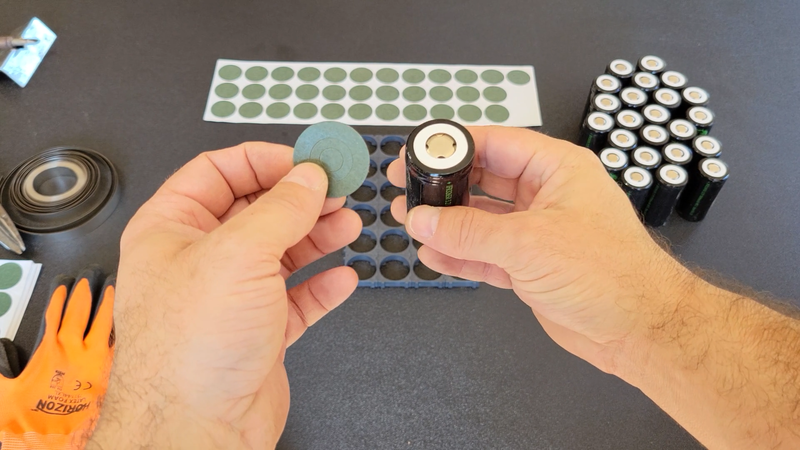
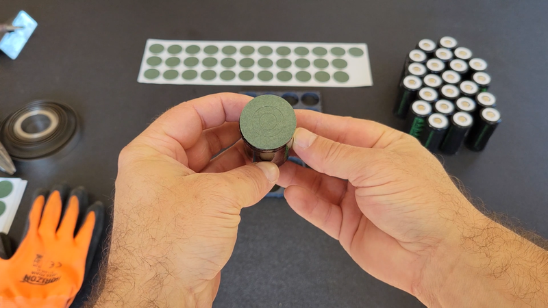
Batteryhookup.com also supplies insulation rings for their cells (sold separately). These have adhesive backings and are meant to cover the positive terminals on the cells to help prevent shorts while you're building your battery. The center of the rings are perforated so a small portion can be removed for making connections when needed. They also provide better insulation between the positive connections and the cell casing to prevent shorts after assembly.
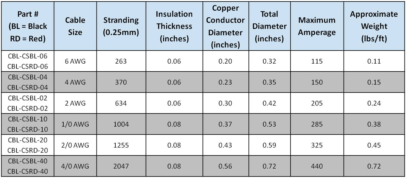
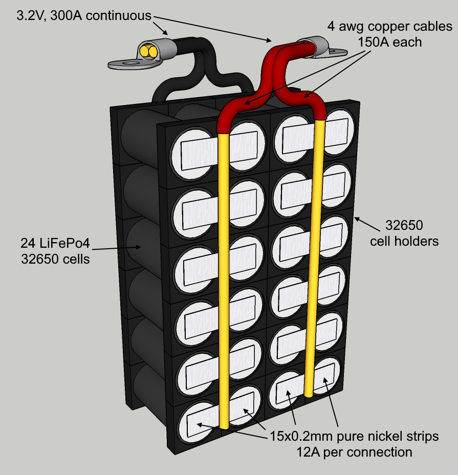
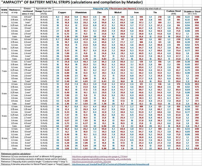
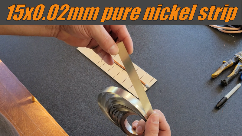
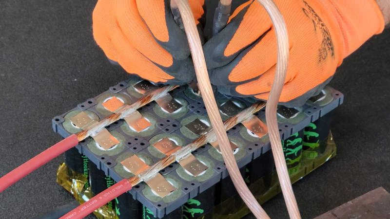
The cells were connected using 15x0.2mm (3 mm^2) pure nickel strips and 4 awg (21 mm^2) flexible copper cable from Windy Nation. As shown in the charts and image below, the cables and strips are sized large enough (cross sectional area in mm^2) to safely handle the current that the motor is going to pull from the battery without overheating, +10-20%.
The ME1616 motor is rated for 250A continuous and 600A peak. One layer of 3 mm^2 pure nickel strip can handle ~12A of current. With current draw being shared by every cell in a parallel (P) group, the nickel strips will only need to handle 250A / 24 cells = 10.4A continuously each. The chart below shows the ampacity of different sizes and types of conductors for connecting battery cells. Note that it only lists strips up to 10mm wide, but it's the cross sectional area of the conductor that determines its ampacity. For example, the 15x0.2mm pure nickel strips that I used have the same ampacity as 10x0.3mm pure nickel because the cross sectional area of both is 3 mm^2.
I should also point out that not all nickel strips that are sold are pure nickel, either. Some are copper or steel with nickel plating. The nickel plated copper strips will have a higher ampacity because copper is more conductive than nickel so thinner strips can be used, but because of the higher conductivity they'll be harder to spot weld to the cells without an expensive, high power welder that can generate enough heat to make a secure weld. Nickel plated steel has a lower ampacity than pure nickel and are easier to spot weld, but thicker strips are needed to compensate and the steel has a potential to rust. Aluminum is a good conductor but isn't common in battery packs, at least not home built packs, because soldering and conventional spot welding methods don't work for aluminum. Tesla has aluminum bus plates in their EV modules, for ex, but use ultrasonic welding (vibrations) for bonding fuse wire to them instead of electrical resistance welding.
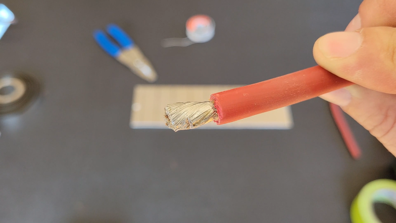
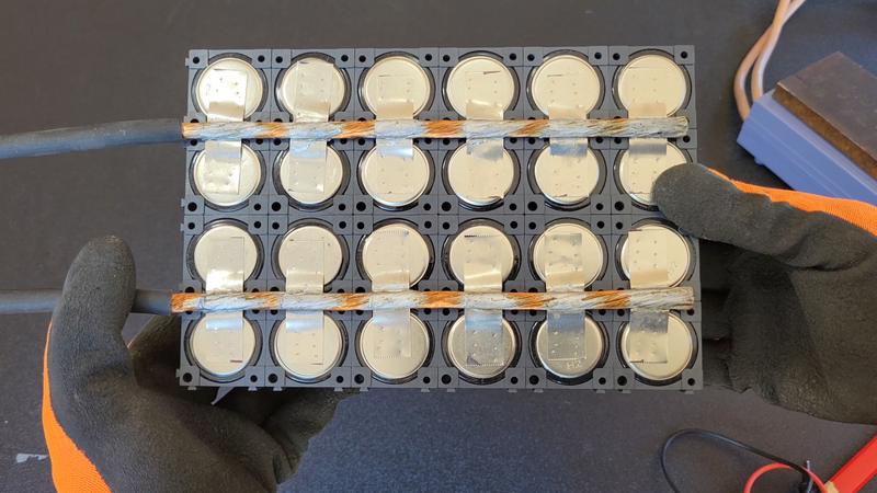
After the cells were assembled in the holders and the insulator rings were installed, I cut the 4 awg cables to length then stripped a short section of insulation off one end and soldered the wire. This kept the wire from unravelling after I stripped the rest of the insulation from it.
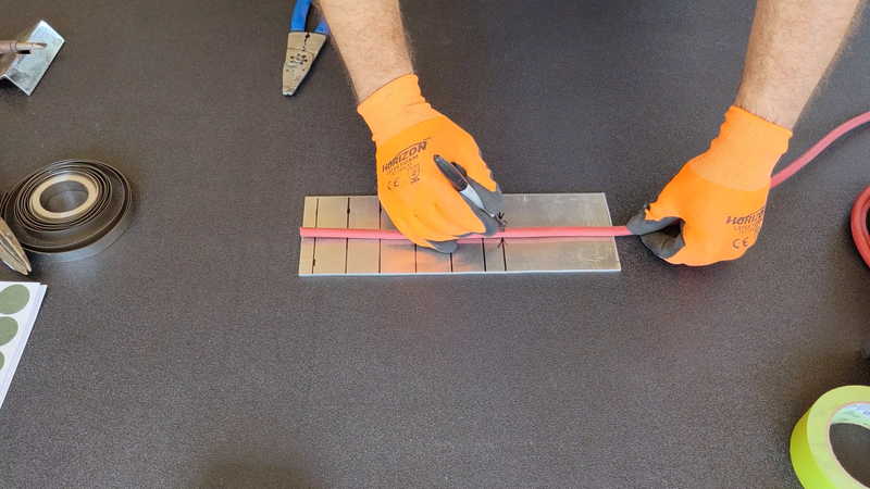
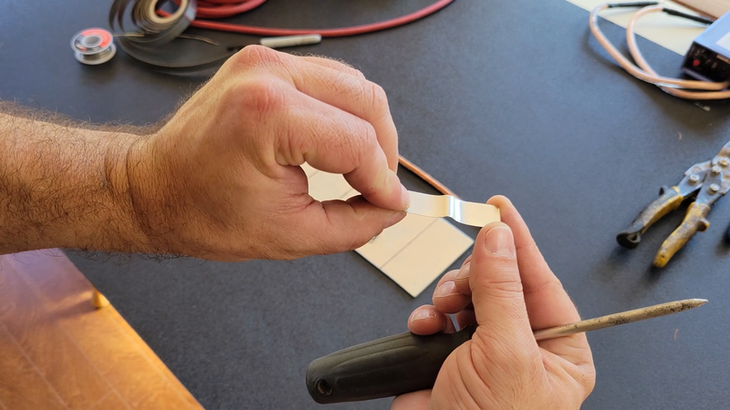
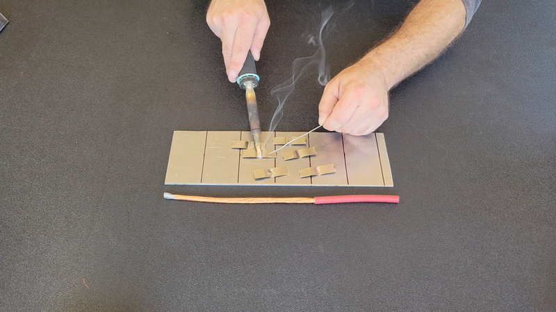
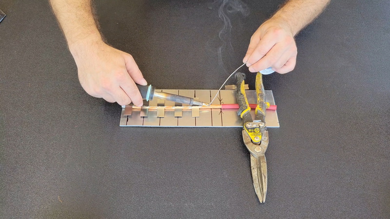
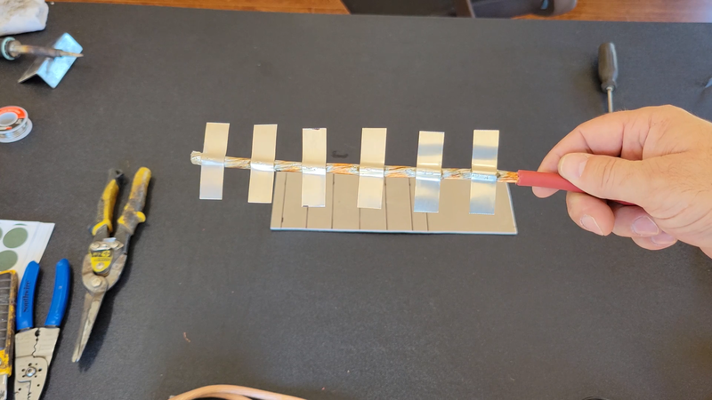
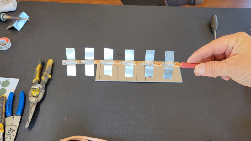
I then cut 6 pieces of nickel strip at 2" long, and bent them around a scratch awl to form a profile that will wrap around a portion of the copper cable. Then I tinned the strips and soldered them to the cable using a Weller W100PG heavy duty soldering iron, 40/60 rosin core solder (NOT acid core), and an aluminum template that I made to space the strips apart at the proper distance and location. The strips should be soldered to the cables BEFORE spot welding them to the cells because soldering to the cable requires a lot of heat that can transfer through the strips and damage the cells.
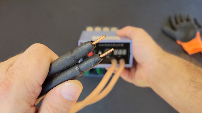
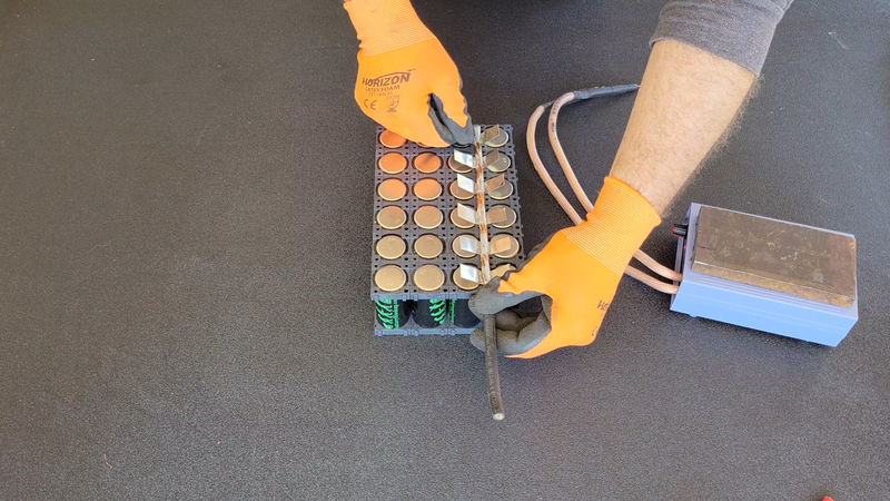
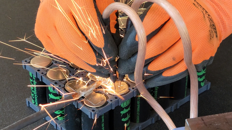
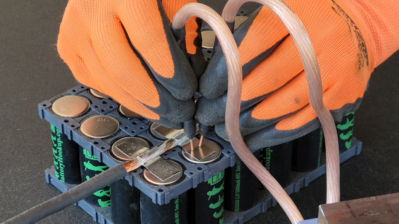
Once the strips were soldered to the cables, I cleaned off any remaining flux with rubbing alcohol, then welded the remaining ends of the strips to the cells negative terminals with a cheap 5000W spot welder, using 3-4 welds per connection. It did the job, the connections are plenty strong enough. But it's limited in the thickness of nickel strip that it can weld, being 0.25mm max, single layer. If you plan on building a big or a lot of batteries, I recommend getting yourself a K Weld. You'll need a powerful welder to make strong, reliable connections, otherwise vibrations from driving your EV later can work a weak weld loose and shut you down. Most of the sub $100 spot welders aren't up to the task.
Another thing to keep in mind is that the job of the welder is to hold the strip flat against the cell terminal, so avoid making unnecessary kinks in the strips where they're to be welded or short spaced center welds that could allow lifting of a portion of the strip and affect the connection and/or create a hot spot in the pack.
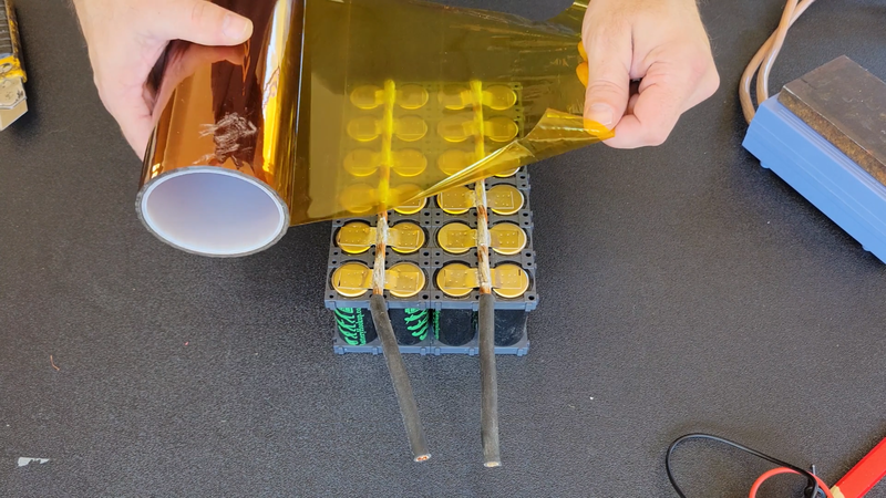
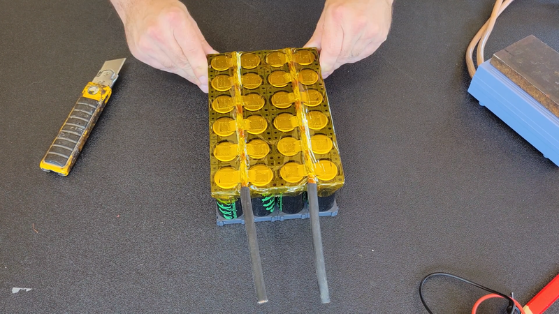
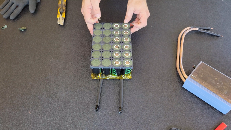
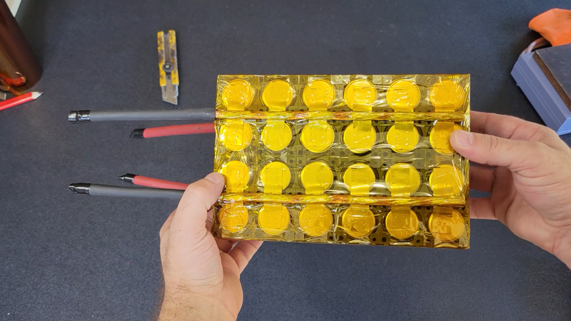
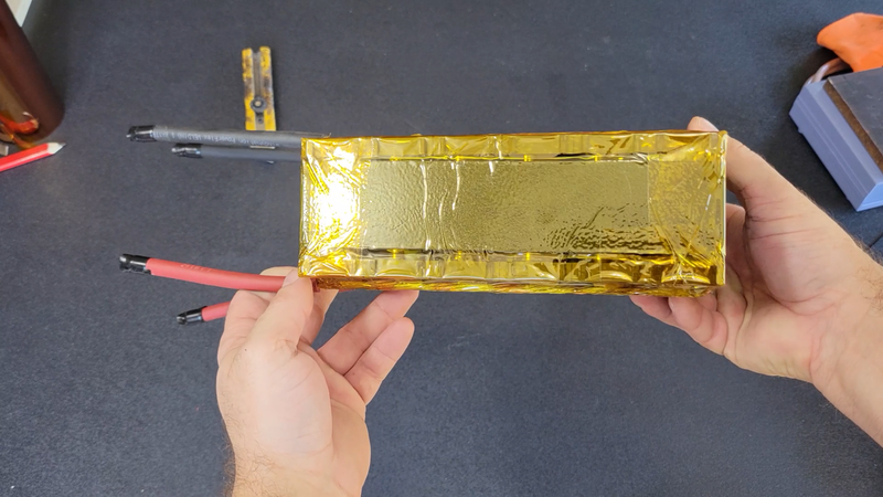
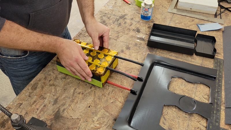
After the negative cables were connected, I covered that side of the module with Kapton tape to seal and protect it, then removed the center tabs from the insulator rings on the positive terminals and spot welded the positive cables in place.
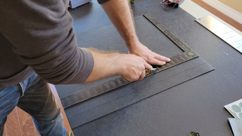
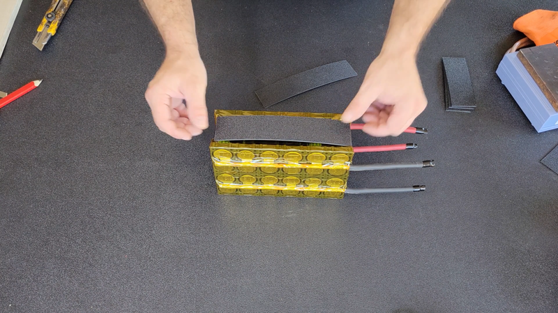
I also cut some strips of 1/16" thick ABS plastic and taped them to the sides, top and bottom of the modules to add more protection to the cells.
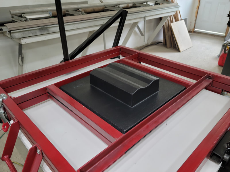
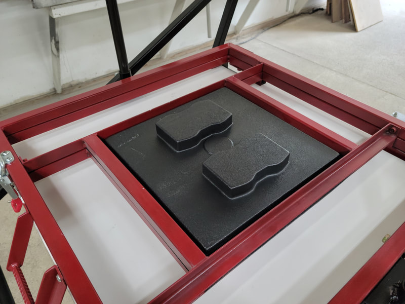
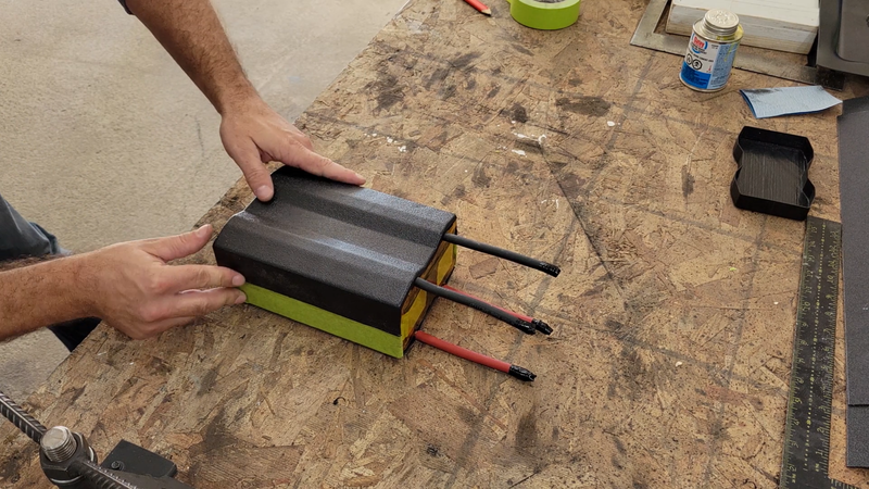
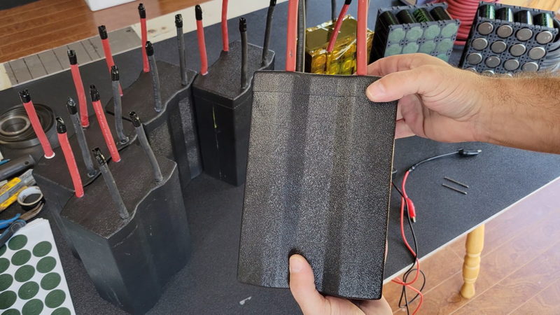
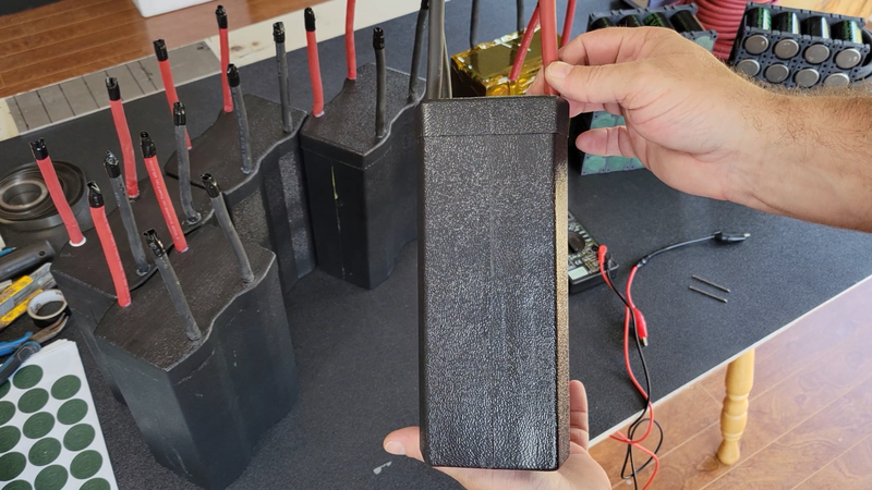
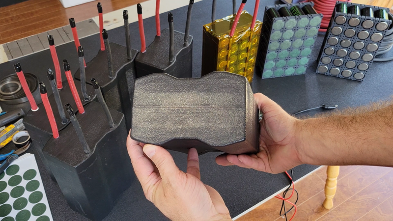
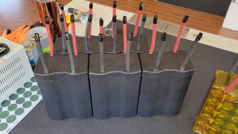
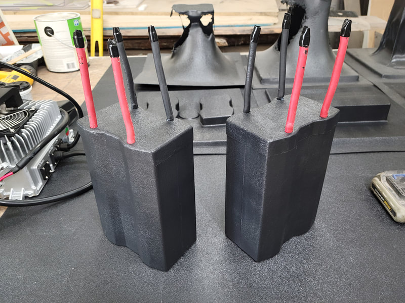
I then used my new vacuum former to make ABS cases for the modules. I built the former last month specifically for this job, but it's going to be a handy piece of equipment to have in the workshop that I can use for loads of other projects, so the time spent building it was well worth it. I recommend checking out the build article to learn how it works and how to build it.
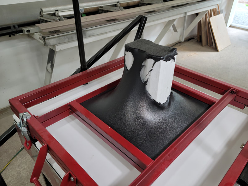
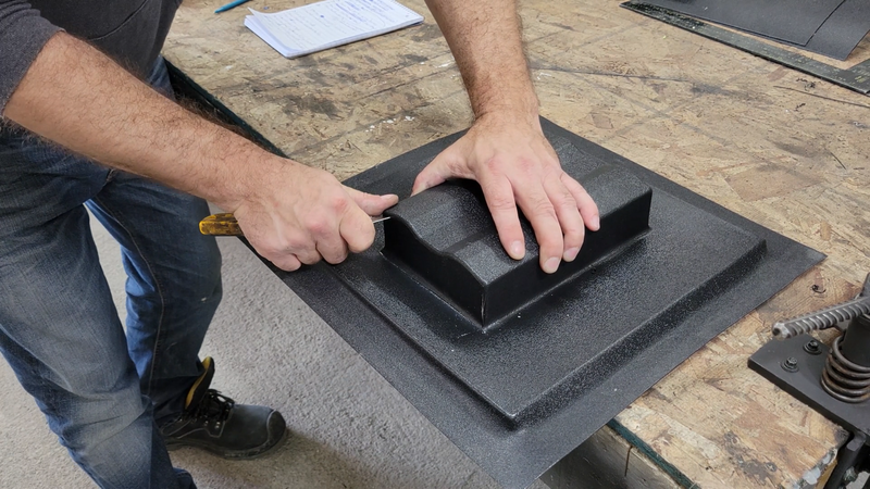
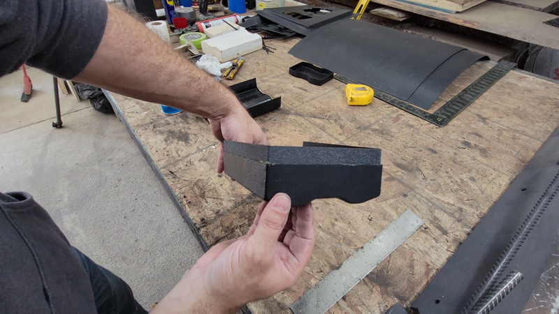
I tried to form the cases in just two pieces, ie: top and bottom, but the draw depth was too much for the sheet size and thickness, and the buck surfaces were too vertical. This caused the first few forming attempts to fail by stretching the ABS sheet too thin and tearing it and causing excess material to bunch up in the corners. I ultimately decided to form the cases in 3 pieces - one short cap for the top and two halves for the longer bottom section.
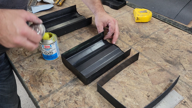
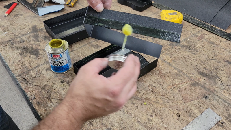
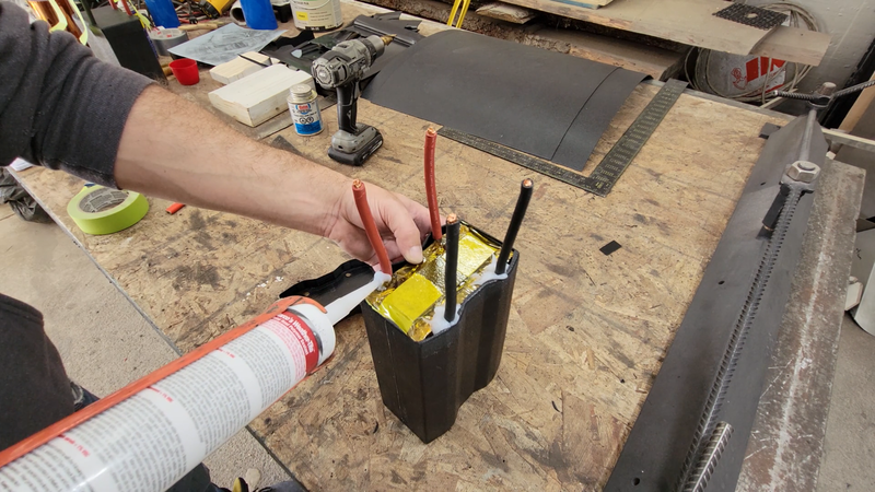
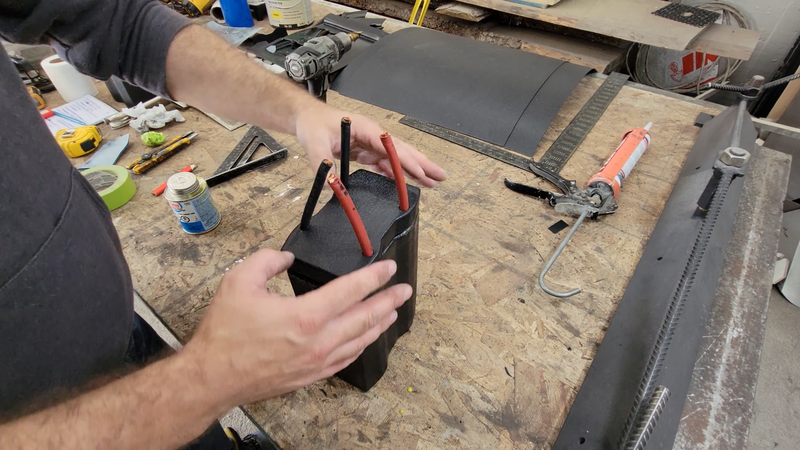
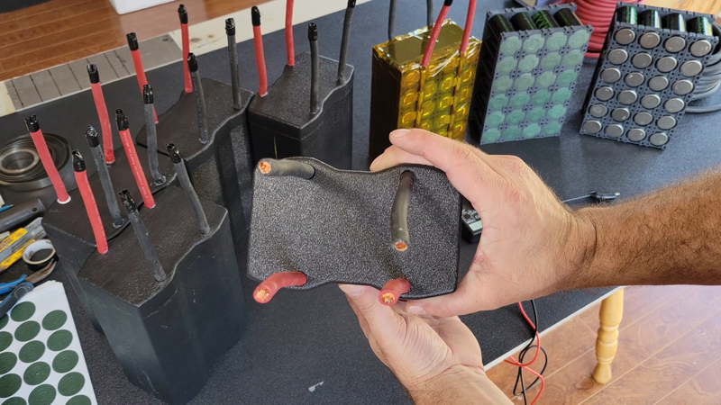
The cases were assembled using ABS backing strips and solvent cement. ABS solvent cement is more than just a glue; it reacts with the plastic to melt it to a point where the married surfaces are chemically welded together when the it cures. It's impossible to separate the joint without breaking the plastic if it's done right, and it's water tight. I also used silicone sealant under the cap where the cables exit, and installed the cap while the silicone was still wet.
I wouldn't go so far as to say that these modules are waterproof and can be submerged completely in deep water, but they're sealed well enough to be partially submerged at least (up to the cable exit locations), and will keep dust and splashes of water away from the cells when I'm riding in the trail or hosing mud off the kart.
14 Comments
|
AuthorJames Biggar Archives
March 2023
Categories |


 RSS Feed