how to build a sheet metal brake
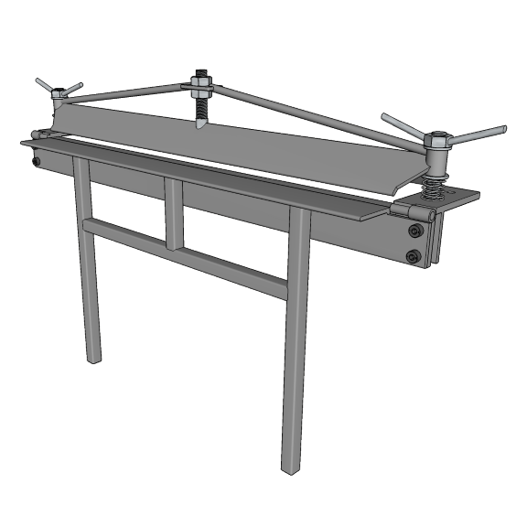
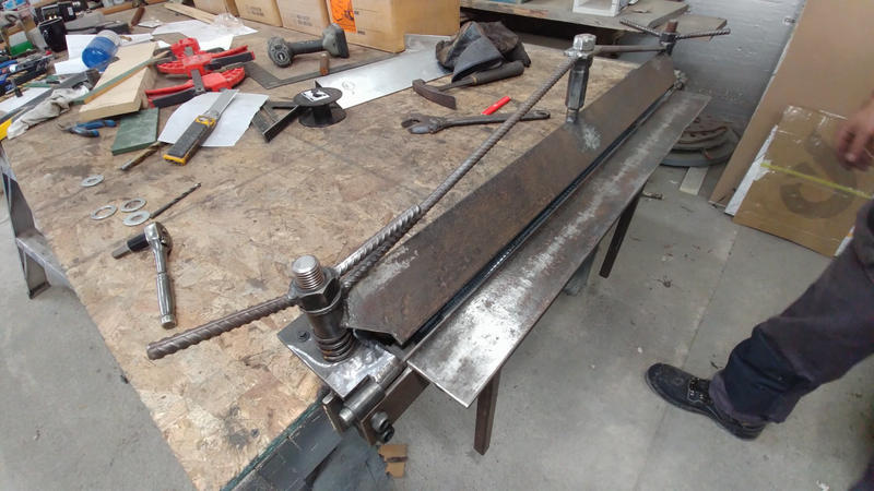
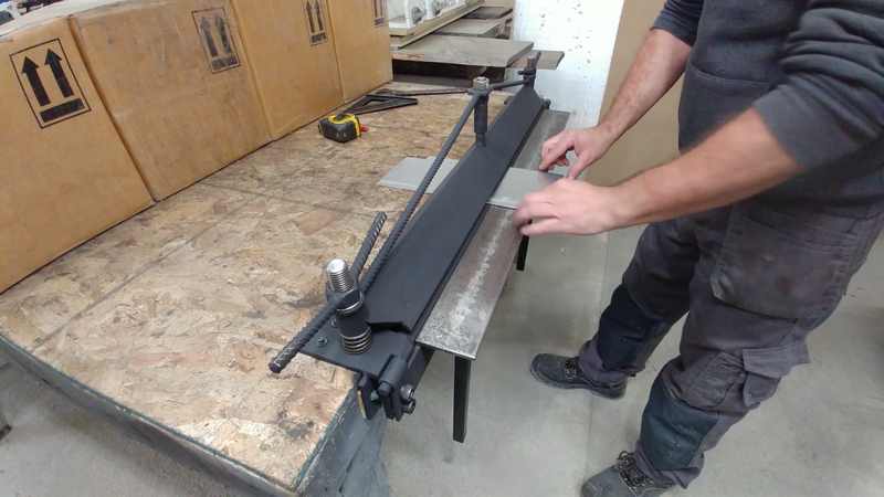
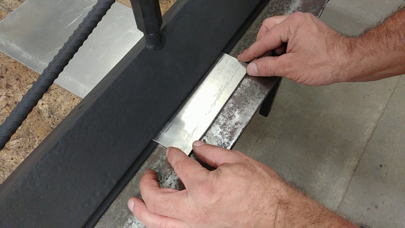
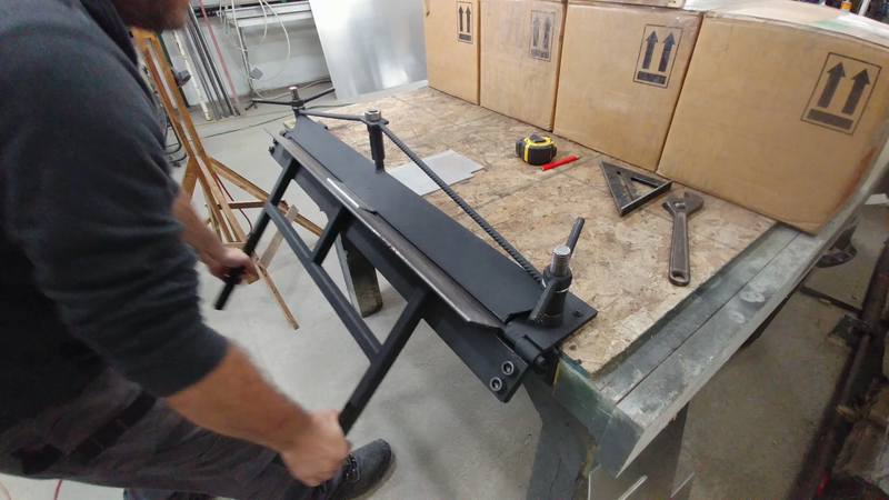
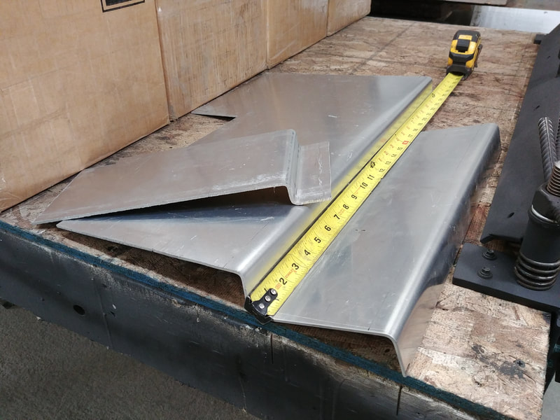
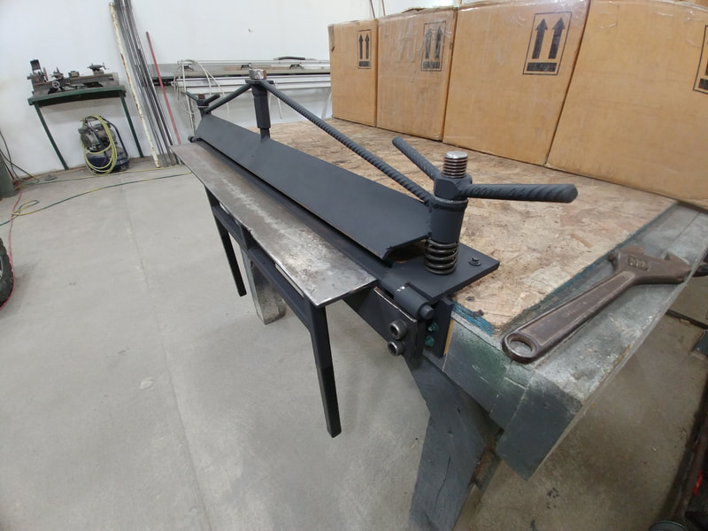
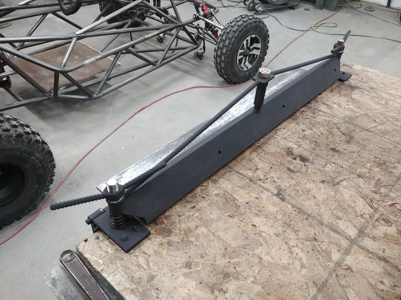
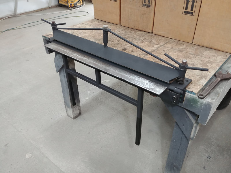
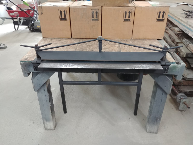
This sheet metal brake can be easily built in a home workshop for next to nothing, and will bend aluminum sheets 1/8" thick and 24" wide, and up to 135°, though it can bend thinner aluminum and steel sheets up to 36" wide. The build article below explains how with detailed step by step instructions. Dimensional drawings and a 3D model for this project are available for download here.
brake SPECS
Dimensions: 41"x6"x8"(LxWxH)
Capacity: <36" wide, 1/8" thick sheet metal
Capacity: <36" wide, 1/8" thick sheet metal
TOOLS NEEDED
Pencil/chalk/marker
Tape measure
Builder’s square
Hacksaw
Files
Hammer
Clamps
Pliers
Allen key set
Combination wrenches
Angle grinder with cut off, grinding, and wire brush wheels
Step drill bit (up to ⅞”)
Mig welder
Tap and die kit
Tape measure
Builder’s square
Hacksaw
Files
Hammer
Clamps
Pliers
Allen key set
Combination wrenches
Angle grinder with cut off, grinding, and wire brush wheels
Step drill bit (up to ⅞”)
Mig welder
Tap and die kit
MATERIALS NEEDED
6” of 1-¼”x0.12” HREW steel tubing
6” of ½” schedule 80 pipe
60” of ½” steel round bar
72” of 3”x3”x1/4” steel angle
12” of ⅞” threaded rod w/ 4 matching hex nuts & washers
36” of 1”x3”x0.12” rectangular steel tubing
78” of 1”x1”x0.12” square steel tubing
6”x6”x3/8” steel plate
6”x6”x1/4” steel plate
Two lawn tractor seat compression springs
Four ½”x3/4” long socket cap screws
suppliers
Steel angle, tubing, etc: https://www.metalsdepot.com/category/steel-products
Compression springs: https://www.ebay.ca/itm/224263132064
Socket cap screws: https://www.ebay.ca/itm/161898212485
Compression springs: https://www.ebay.ca/itm/224263132064
Socket cap screws: https://www.ebay.ca/itm/161898212485
makING THE bed
STEP 1
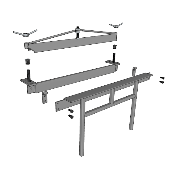
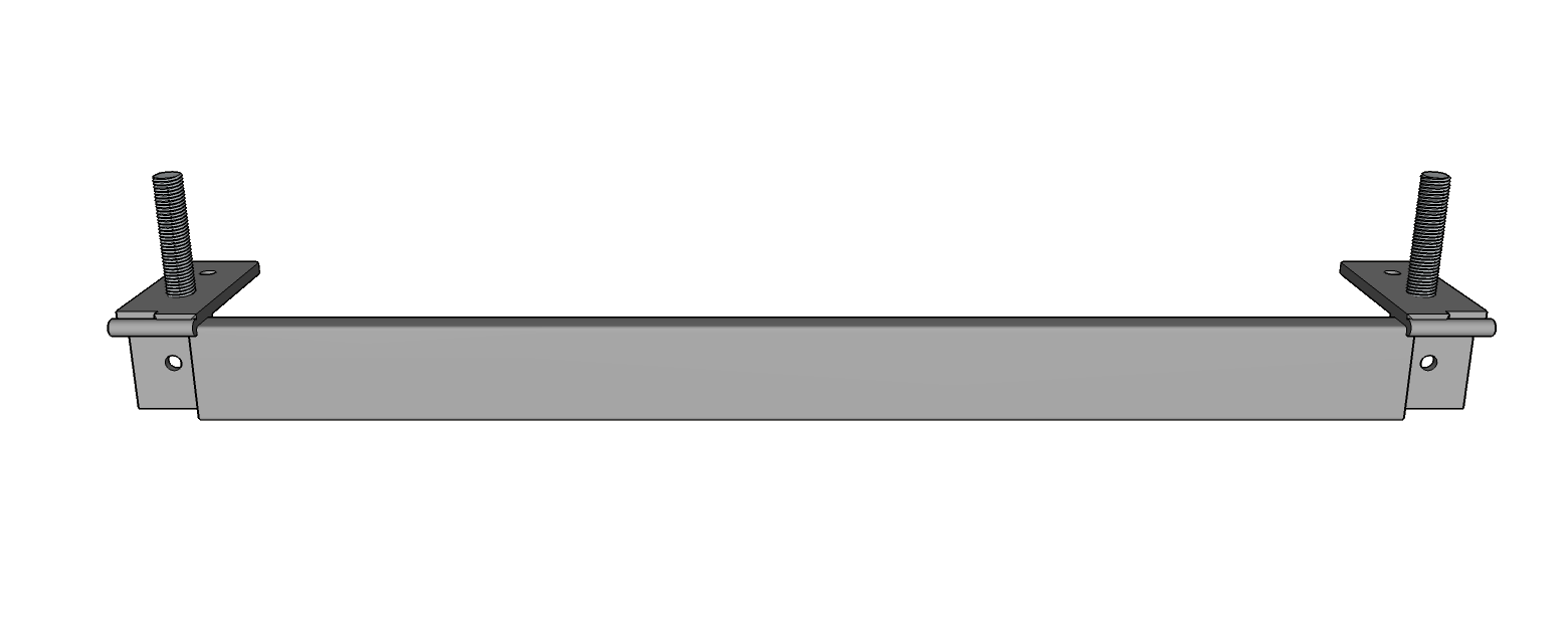
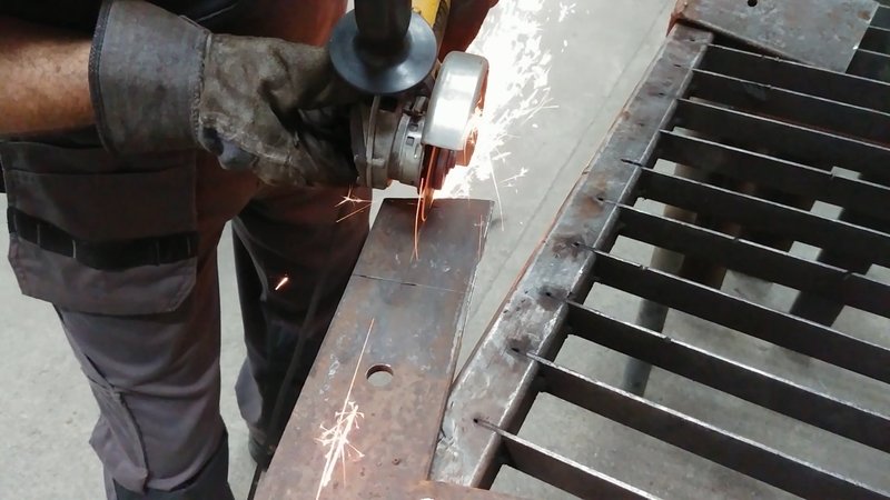
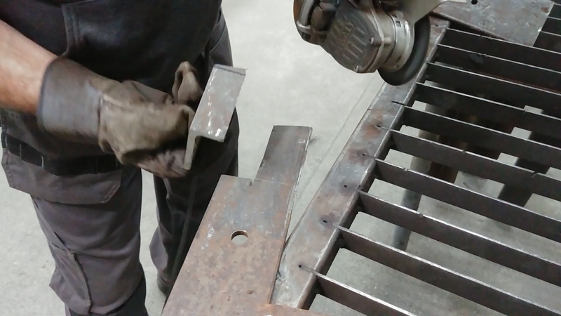
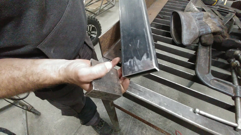
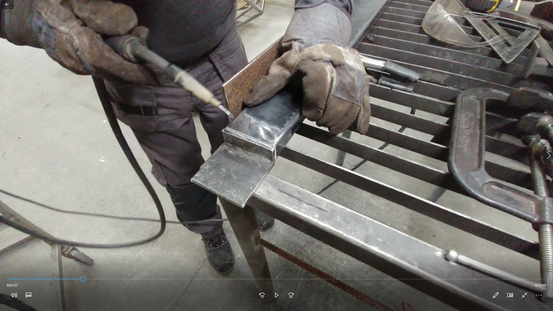
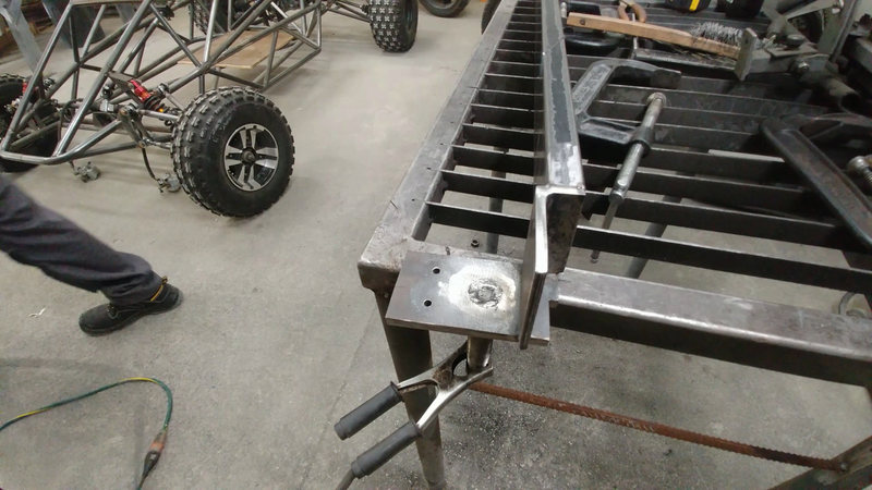
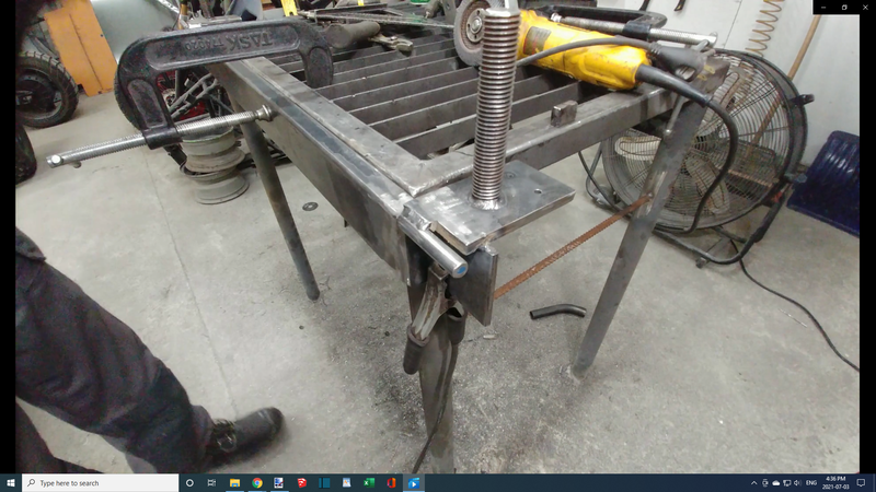
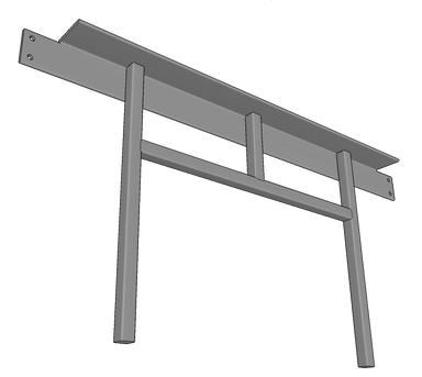
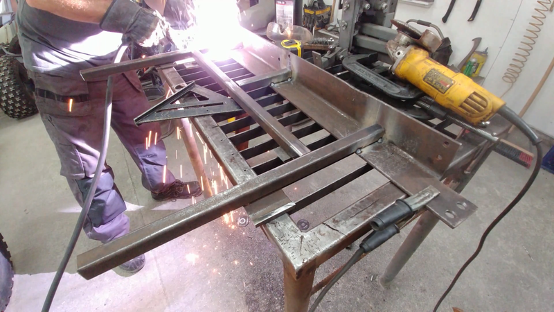
From 3"x3" steel angle, cut two pieces according to the dimensions shown in the plans, then tack weld them to a piece of 1"x3" rectangular tube. The angles will be mounting flanges and the 1x3" tubing is the bed that future sheet metal workpieces will be clamped to. The flanges are approx. 1/4" wider than the 1x3" tubing in order to keep the bed away from the table edge that it's mounted to. The space between them will allow you to form multiple alternating bends in one workpiece (refer to time stamp 12:25 in the build video), so feel free to set this gap to your preference but bear in mind that the pieces that will be added in the next step will need to be adjusted accordingly.
STEP 2
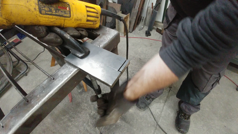
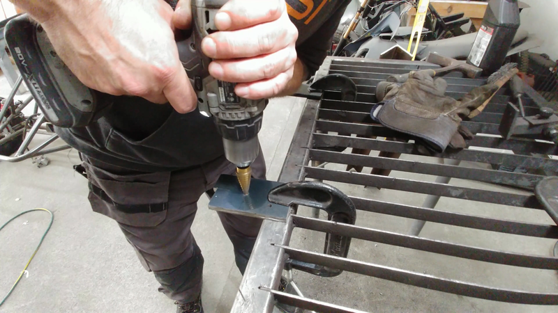
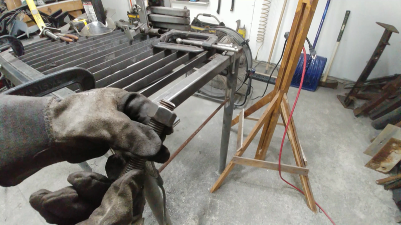
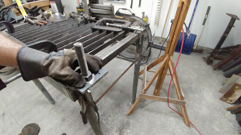
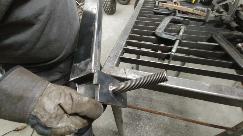
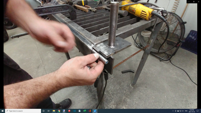
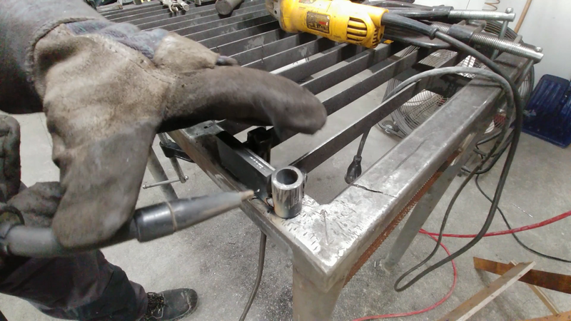
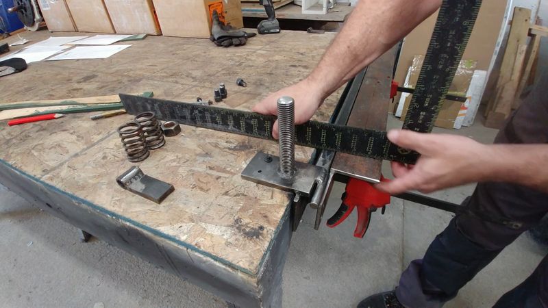
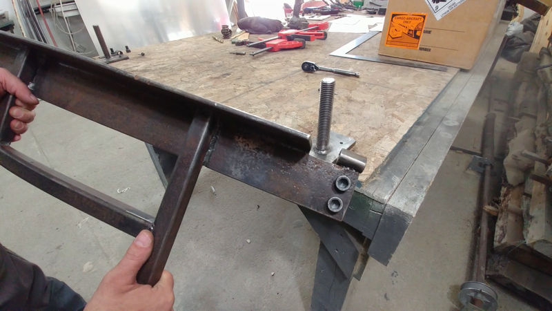
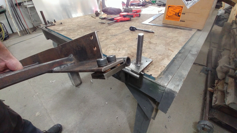
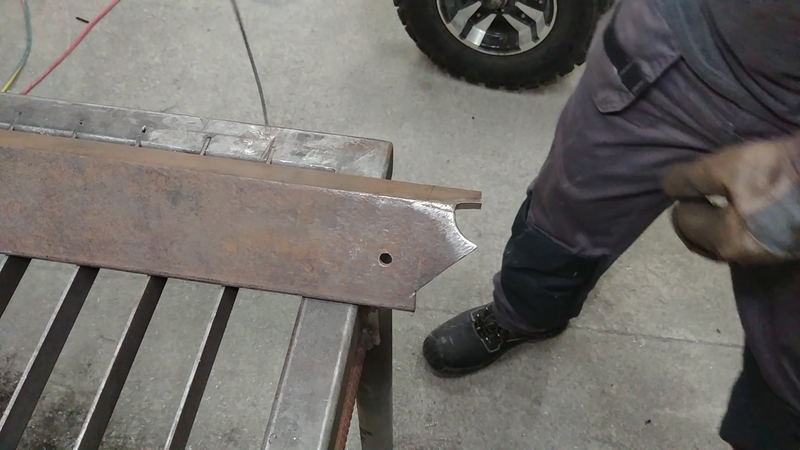
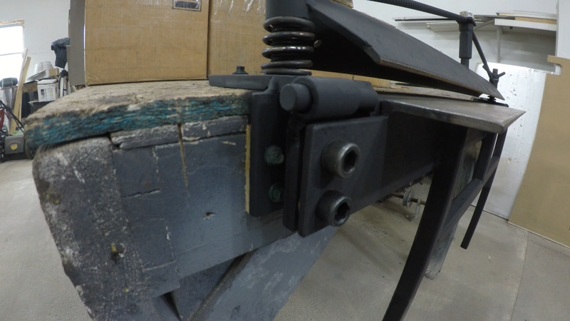
Cut two more mounting flanges from 3/8" steel plate, and notch them to the dimensions shown in the plans. Then drill them to receive a 7/8" threaded rod. Tack weld these to the bed as shown and chamfer the front, bottom edge of the upper flange to receive a 1/2" round bar. The threaded rod will guide the clamping bar and allow you to tighten it to the bed. The round bar will serve as the pin for the leaf hinge.
MAKING THE leaf
STEP 3
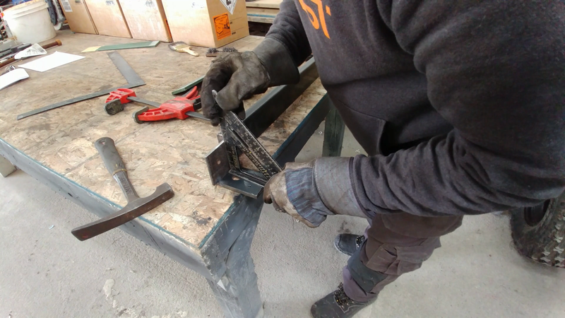
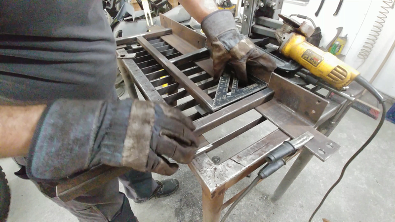
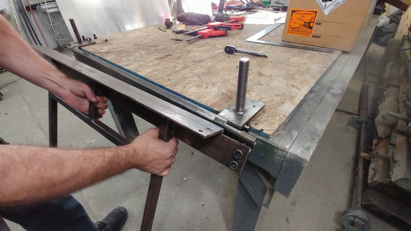
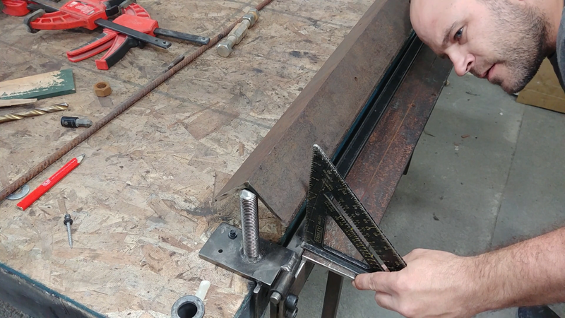
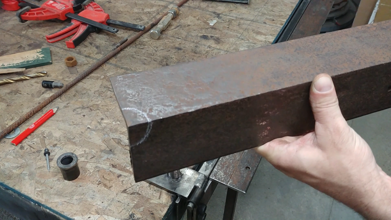
Cut the leaf from 3"x3"x1/4" steel angle according to the dimensions shown in the plans, then drill the ends to receive 1/2"-13x3/4" socket cap screws later. Fasten the bed to the table that you intend to mount it to, then clamp the leaf to the bed and check that everything is centered and flush with a straight edge. It wouldn't hurt to place a very thin piece of flashing between the bed and the leaf before clamping them together to allow some wiggle room for the leaf when it's being used.
STEP 4
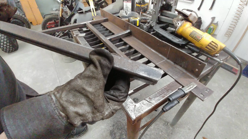
Cut some 1x1" square tubing to length and tack it to the leaf to form the handles. Use a third piece in the middle for reinforcement. This will help keep the leaf from twisting when bending thick sheet metal.
STEP 5
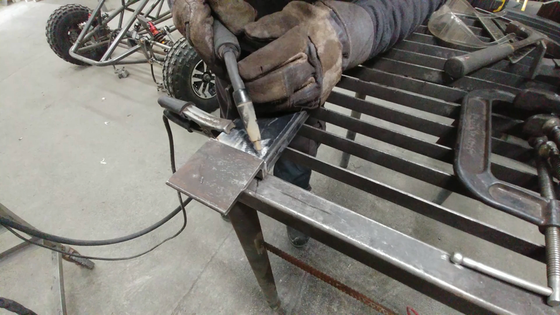
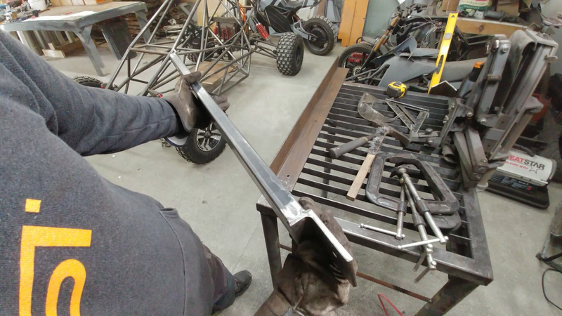
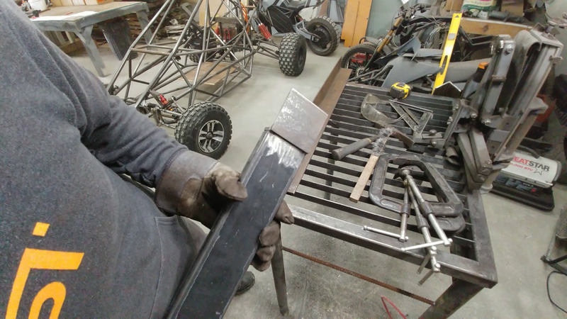
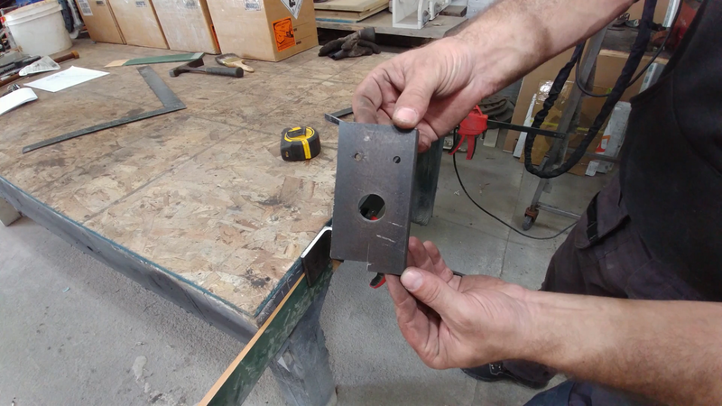
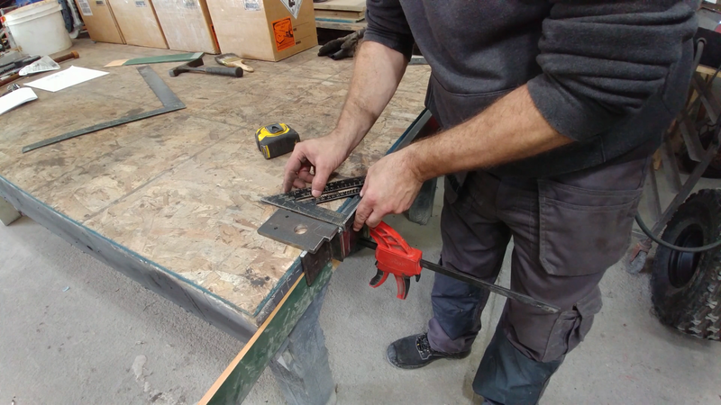
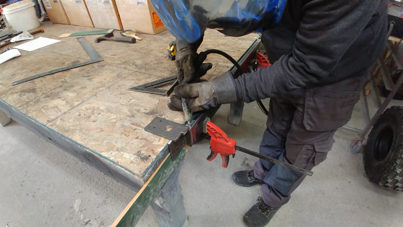
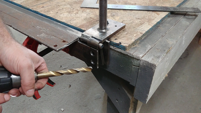
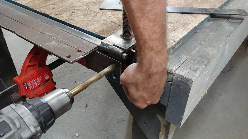
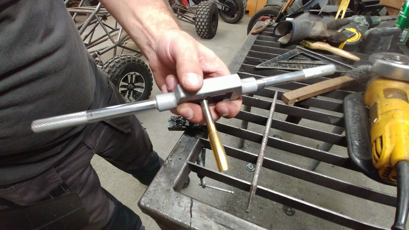
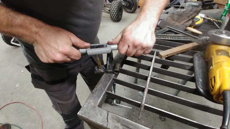
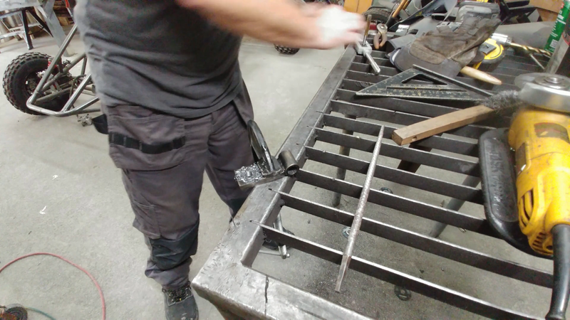
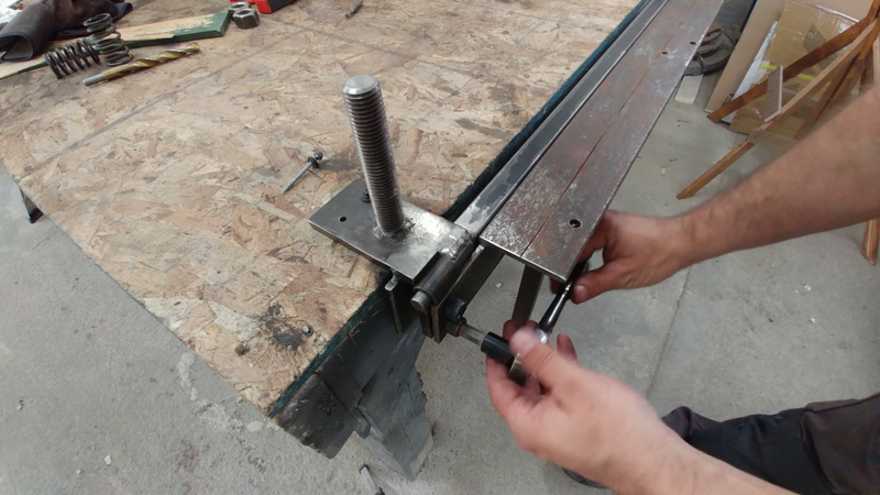
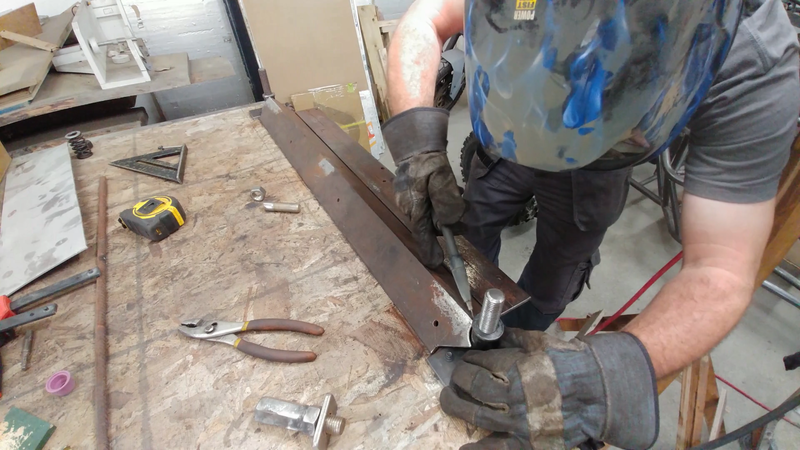
Cut a piece of 3/8" plate and 1/2" schedule 80 pipe to size and fasten them together as shown. These will form the hinge plates. The center of the pipe needs to line up with one face of the plate - this is critical for the brake to work properly, so take your time to be as precise as humanly possible. Once they're welded together, slide them onto the hinge pins, behind the leaf with the offset portion of the pipe facing forward. Use a drill to mark the holes for the socket cap screws onto the hinge plates, then drill and tap them.
STEP 6
Connect the hinge plates to the leaf with the socket cap screws and test that it operates properly.
MAKING THE clamp
STEP 7
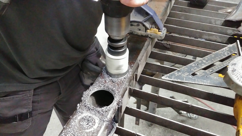
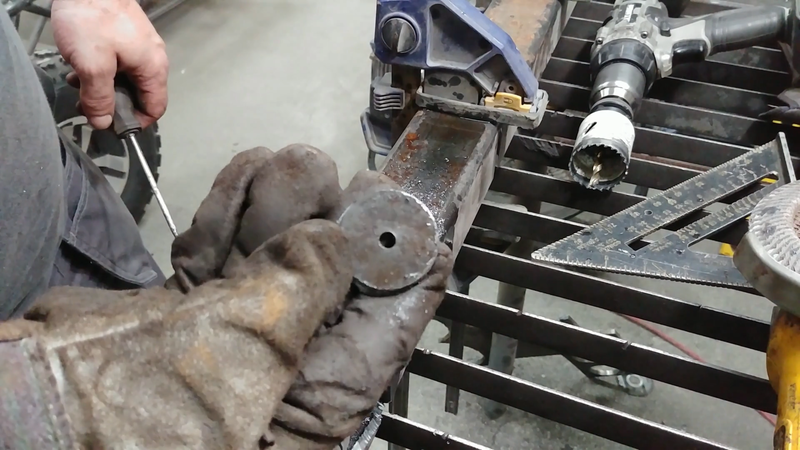
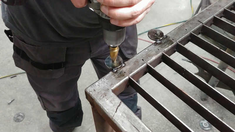
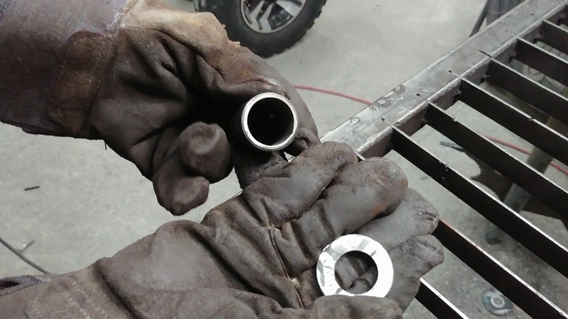
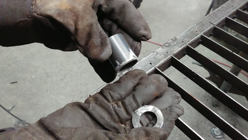
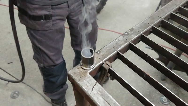
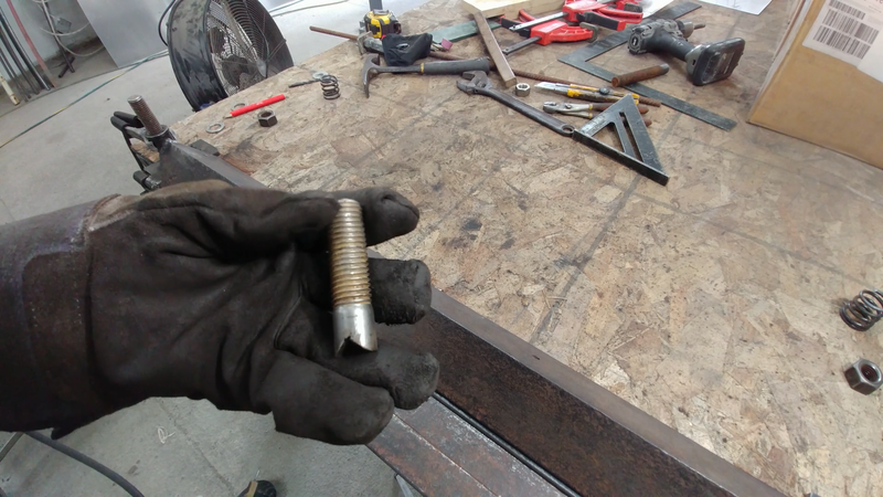
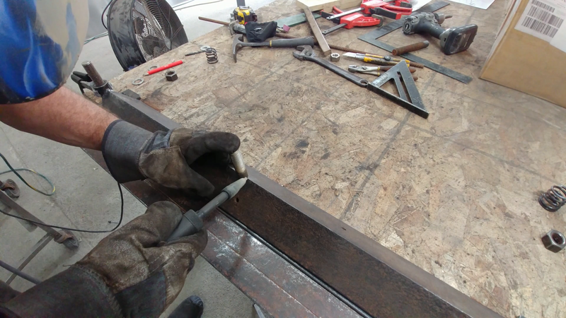
Use a 1.25" bi-metal hole saw to cut two circles from a 1/4" steel plate. Cut two pieces of 1.25"x0.12" tubing to length and tack the circular plates to one end of each tube. These will be part of the clamp guide that fits over the threaded rod.
STEP 8
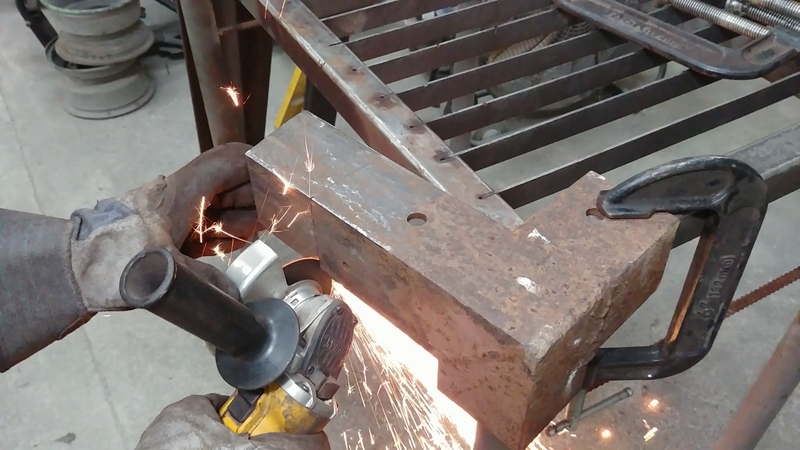
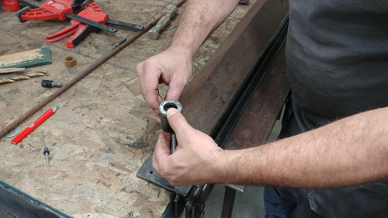
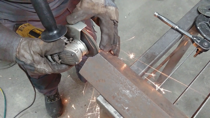
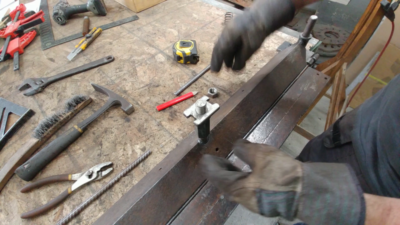
Cut a piece of 3x3x1/4" steel angle for the clamping bar, then center it over the threaded guide rods as shown. Place the tubes from the previous step over the threaded rods and mark their positions onto the steel angle. Then remove those portions of the steel angle with an angle grinder to cope the tubes into each end.
Set the clamping bar back into position on the bed, making sure that it's set back from the center of the hinge exactly the same distance as the thickness of the metal that you intend to bend. Different thicknesses of metal will require different setbacks as well as a different radius on the leading edge of the clamping bar - if the radius is too tight for a certain thickness, it could cause the metal to break. Thus, different sheet metal thicknesses will require making different clamping bars to suit them, or removable 'fingers' of different thickness and radii that can be bolted to the clamping bar when needed. The brake featured here is set up for 1/8" sheet metal. What you set up at this stage is entirely up to you. Once the clamp is set, tack weld the tubes to the ends.
Set the clamping bar back into position on the bed, making sure that it's set back from the center of the hinge exactly the same distance as the thickness of the metal that you intend to bend. Different thicknesses of metal will require different setbacks as well as a different radius on the leading edge of the clamping bar - if the radius is too tight for a certain thickness, it could cause the metal to break. Thus, different sheet metal thicknesses will require making different clamping bars to suit them, or removable 'fingers' of different thickness and radii that can be bolted to the clamping bar when needed. The brake featured here is set up for 1/8" sheet metal. What you set up at this stage is entirely up to you. Once the clamp is set, tack weld the tubes to the ends.
STEP 9
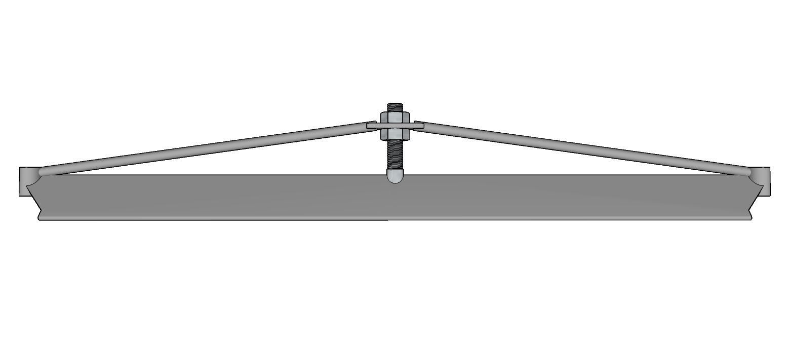
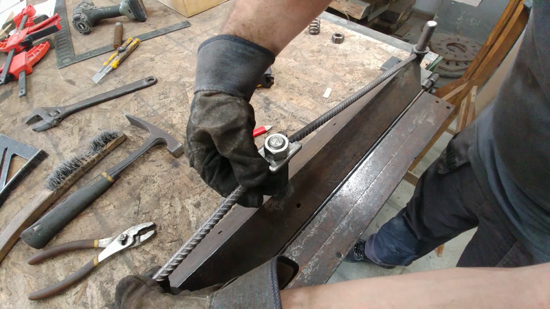
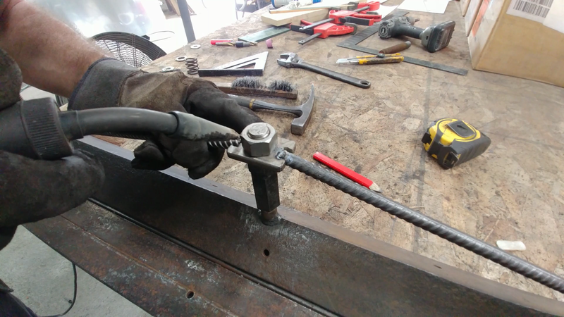
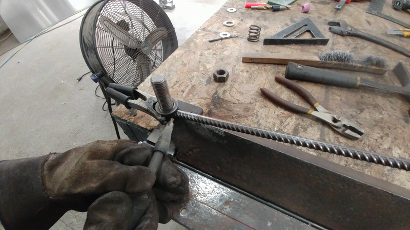
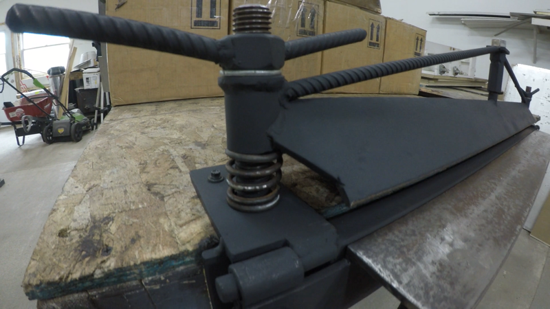
Cut a piece of threaded rod with a 'v' notch in the bottom and tack it to the top, center of the clamp bar. Thread a hex nut on approx. halfway, then cut and drill a piece of 1/4" plate to the dimensions shown in the plans and set it on the hex nut. Cut two pieces of 1/2" round bar and tack one end of each to the plate on the hex nut (do not weld the hex nut to anything), and tack the other ends to the corners at the top ends of the clamp. These will form an adjustable truss to add strength to the back of the clamp and allow you to adjust how much pressure is on the center of your workpiece.
STEP 10
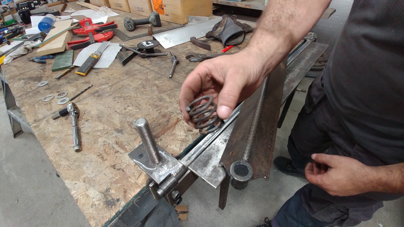
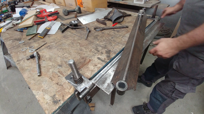
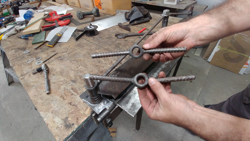
Cut four pieces of 1/2" round bar and weld two to each of the 7/8" hex nuts for the threaded guide rods. These will be the 'T' handles for tightening the ends of the clamp to your workpiece. Remove the clamp from the bed and place a compression spring over each guide rod, then put the clamp back in place and tighten it down to a scrap piece of sheet metal to check that the clamp works properly. If you find there's a gap between the clamp and the workpiece in the center or at the ends, adjust the hex nut on the truss to push or pull the center of the clamp where you need it to be.
When you're satisfied, test bend a short piece of sheet metal. If it bends fine, test a wider piece. The wider the workpiece is, the more force it will take to bend. You might find that pieces nearing the capacity of the brake may have a slight concave in the middle on the leaf side after bending. It's best to test bend to capacity with scrap pieces in order to gauge exactly what your brake is capable of bending and what pushes the limits of your welds. The strength of the brake lies as much in the hinge pin as it does the steel clamp and leaf, and it will only be as strong as the welds that you produce. If you're a beginner at welding, you might end up breaking it a few times before you get it right. If you're experienced, then I'm just wasting your time now. Enjoy your new brake!

