Sizing Your Charge Controller & Power Inverter |
|
Charge Controller Types: PWM Vs MPPT
If you want to charge batteries, then you're going to need a charge controller. A charge controller will control the power input to the batteries when they're charging, and will turn off or divert the power input when the batteries are fully charged to protect them from damage.
There are two main types of charge controller: pulse width modulation controllers (PWM), and maximum power point tracking controllers (MPPT)
There are two main types of charge controller: pulse width modulation controllers (PWM), and maximum power point tracking controllers (MPPT)
Sponsored by
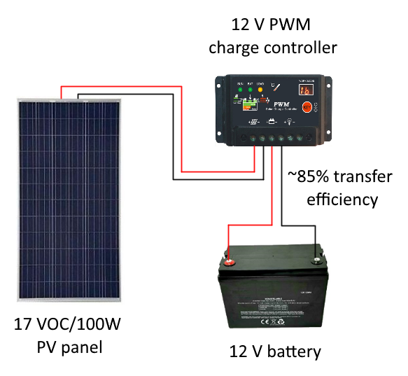
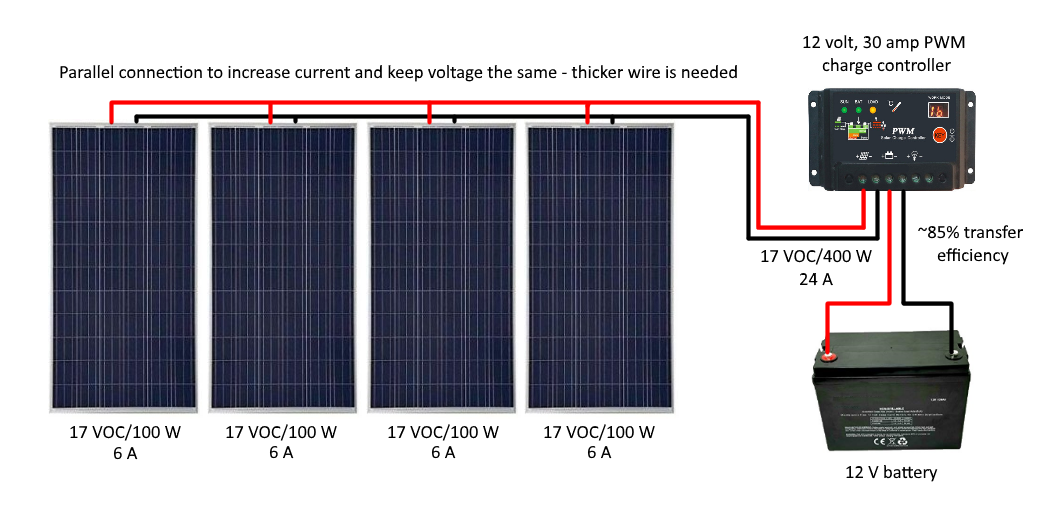
PWM controllers were among the first introduced to the market years ago and are still common today. They are the simpler and more affordable controller type, but they're also less efficient compared to MPPT (~80% for PWM versus ~98% for MPPT). PWM controllers are basically switches that rapidly connect and disconnect a power source to and from the batteries to optimize charge and regulate voltage. These controllers are usually designed for charging 12, 24, or 48 V battery banks, and will drag the voltage of the power source down to the voltage of the battery bank that it's connected to, if required. But there's a loss of power as a result.
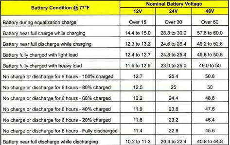
For example, a standard 32-36 cell, 100-150 watt solar pv panel will output somewhere between 17-19 open circuit volts, which is ideal for charging a 12 V battery (the charging voltage will always need to be a few volts higher than the battery bank voltage at full state of charge - see chart below).
For example, a standard 32-36 cell, 100-150 watt solar pv panel will output somewhere between 17-19 open circuit volts, which is ideal for charging a 12 V battery (the charging voltage will always need to be a few volts higher than the battery bank voltage at full state of charge - see chart below).
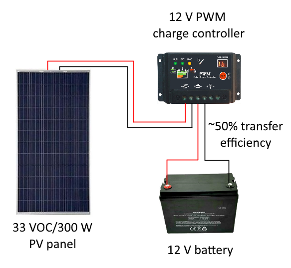
In this scenario, a PWM controller won't need to drag the charge voltage down to suit the battery voltage. However a 60 cell, 300 watt panel will output around 33 open circuit volts. A person 'could' connect this panel to a 12 V battery via a PWM controller as long as the controller is rated to handle the higher input voltage, but the controller would just drag the voltage down from 33 V to around 17-18 V to suit the battery, which means that nearly half of the power from the panel will be lost. So when using a PWM controller in your system, you'll need to make sure that the open circuit voltage rating of the panels (and the array as a whole) and the voltage rating of the controller is suitable for the battery bank voltage in order to minimize losses and prevent damaging the controller.
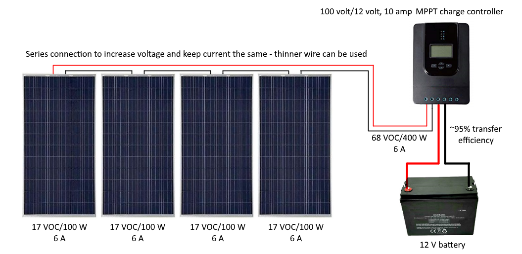
As mentioned previously, MPPT controllers are more expensive but more efficient than PWM controllers. Maximum power point tracking controllers are intelligent controllers that use an algorithm that constantly measures the power coming from a solar array or wind turbine, and adjusts the charge voltage and current to suit the batteries and optimize efficiency. MPPT controllers are designed for charging 12, 24, or 48V battery banks, but they're also designed to allow a high input voltage from the power source, usually up to 200 V but this will differ between manufacturers. Unlike a PWM controller, there's no or very little loss in power when an MPPT controller lowers input voltage to match battery voltage because it will increase the current (amps) to compensate and allow the same power to the batteries (volts x amps = watts). This helps with array design/configuration, because multiple larger panels can be connected in series before the controller to increase voltage and minimize wiring requirements. If the panels need to be connected in parallel to keep the voltage low and matching the batteries, then that increases the current (amps) x the # of panels instead of the voltage, and subsequently the required gauge for the transmission wires will also need to increase in order to minimize resistance and carry the current safely, which will increase the cost of an installation. This is why most large off grid installations done today are utilizing large panels and MPPT controllers. This controller may be more expensive, but thanks to its efficiency there are cost savings to be had.
Diversion ControllersPWM and MPPT controllers are both available for solar, wind, or hydro power applications. However, controllers for wind and hydro systems differ from controllers for solar PV systems. A solar charge controller is the standard type, and simply limits or completely cuts off power input to the batteries when they're charged. Because solar panels have no moving parts, this is no cause for concern.
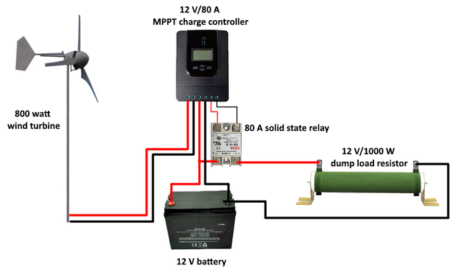
If a wind turbine were connected to a standard solar charge controller, then when the controller begins to limit or cut off power to the batteries, the wind turbine will become 'unloaded' and the blades can spin out of control, known as "free wheeling". Not only is this dangerous for any bystanders, it also causes excess wear on bearings, speeds up edge erosion on the blades, and puts the generator at risk of burning itself out. The same is true when it comes to hydro generators. To prevent free wheeling, a wind or hydro power specific controller needs to be used. These are called diversion or dump controllers. They're designed so that when the battery bank is completely charged and the controller goes into float mode, excess power from the turbine is diverted to a dump load to keep it operating under a load at all times while keeping the batteries from being overcharged. When the battery bank voltage begins to drop below a user set point, the controller will automatically switch the power supply back to the batteries again. A dump load can be anything from another bank of batteries to a bank of resistors or water heating elements - anything that matches the battery bank voltage and slightly more than the total wattage of the incoming power supply, ~ 20%. Refer to the controller manufacturer's instructions for connecting a dump load to their equipment. |
|
Charging Modes
Your charge controller will operate in one of three charging modes; boost charge, float charge, and equalization charge.
Boost charge is just as it sounds. This charging mode allows the maximum amount of power possible to the batteries without damaging them, in order to bring them up to a full state of charge (SOC) as soon as possible.
Float charge occurs when your battery bank is fully charged, but the controller lowers the charging voltage and current to a small trickle charge just to compensate for the banks natural discharge and keep it topped up.
Equalization charge will occur for a short period once per month, and is sometimes programmable in the controller. This mode will slightly overcharge the batteries for a short period to desulphate the plates and help balance out the SOC of each battery in the bank. This helps to improve the health of the battery bank and prolong its life.
Sizing A PWM Charge Controller
Sizing a PWM controller is relatively simple. For example, a person wants to power an aeration system for a fish pond. The power supply is a 1000 watt solar PV array, the storage is a 12 V battery bank, and they want to use a PWM controller because it's just a small system which doesn't require or justify an expensive MPPT controller.
Because the battery bank is only 12 V and the PWM controller will limit input power to just a few volts above the battery's full SOC level (ie: 17-19 V), the panels should have an open circuit voltage rating that matches the battery bank to minimize losses. Looking over some manufacturer spec's, a 100 watt panel produces 17-19 V open circuit, so if ten of them were connected in parallel then that would amount to 1000 watts while staying within the charging voltage range of the battery bank.
The next thing to figure out is how much current will be delivered to the charge controller/battery bank. If the input voltage is 17 V and the total power is 1000 watts, then the current would be watts divided by volts: 1000 / 17 = 58.8 amps
At times, the sun can deliver much more energy than the 1000 watts per square meter conditions that solar panels are tested in and rated for, so it's always best to oversize the charge controller by around 20-25% to prevent damage from potential power surges. For the example above: 59 amps x 1.25 = 73.8 amps. So a PWM controller rated for 12 V and at least 74 amps is needed. It's highly unlikely that a 74 amp charge controller exists, but there are 80 amp charge controllers. If one can't be sourced affordably, then the PV array can be split into two separate systems, and two 12 V, 40 amp PWM charge controllers can be used to charge the battery bank instead of the one 80 amp controller.
Sizing An MPPT Charge Controller
As mentioned previously, MPPT controllers can accept a high input voltage and convert it down to the appropriate charge voltage for the battery bank without loosing power by substituting with more current (volts x amps = watts). Because of this, there are two voltage ratings that you need to consider when sizing an MPPT controller; the input voltage rating and the charge voltage rating. The input voltage rating should match the voltage coming in from the power source, +25% to compensate for voltage spikes on cold, sunny days. So if there will be 66 V total coming in from two 300 W panels connected in series (based on the manufacturer's power rating), then the controller should be able to handle at least 66 x 1.25 = ~83 volts. Most MPPT controllers can handle between 100-200 V, but it's important to check the rating and be sure. The charge voltage will be either 12, 24, or 48 V - some controllers can handle all and will auto-select the appropriate charge voltage when connected to the battery bank.
The next thing you need to determine is the boost current. The boost current is the total amps that will be delivered to the battery after the controller adjusts the voltage from the power source. The boost current will almost always be higher than the current coming from a high voltage power source. For example, if you connected two 33 V/300 W panels in series, the result would be 600 W at 66 V. The current would be 600 divided by 66 = ~9 amps. If those panels are connected to an MPPT controller with a 100 V input rating to charge a 12 V battery, then in order to deliver the same or close to the 600 W coming from the panels after dropping the charge voltage to suit the battery, the controller has to increase the current from 9 amps to around: 600 / 12 = 50 amps. Remember to add another 25% to account for power surges on cold, sunny days when the panels are likely to operate more efficiently. 50 x 1.25 = 62.5 amps. So the boost current is around 63 amps, which means a 70 or 80 amp controller would suffice. Always remember that the boost current is what an MPPT controller's amp rating will be based on. If a person were to try to connect a 10 amp controller to the same array and charge a 12 V battery, then the controller would likely burn out before they finish their morning coffee the day after installation is complete. To find your boost current, just divide the total power of your array or turbine in watts by the voltage of your battery (bank), then multiply by 1.25 to increase the result by 25%.
The next thing you need to determine is the boost current. The boost current is the total amps that will be delivered to the battery after the controller adjusts the voltage from the power source. The boost current will almost always be higher than the current coming from a high voltage power source. For example, if you connected two 33 V/300 W panels in series, the result would be 600 W at 66 V. The current would be 600 divided by 66 = ~9 amps. If those panels are connected to an MPPT controller with a 100 V input rating to charge a 12 V battery, then in order to deliver the same or close to the 600 W coming from the panels after dropping the charge voltage to suit the battery, the controller has to increase the current from 9 amps to around: 600 / 12 = 50 amps. Remember to add another 25% to account for power surges on cold, sunny days when the panels are likely to operate more efficiently. 50 x 1.25 = 62.5 amps. So the boost current is around 63 amps, which means a 70 or 80 amp controller would suffice. Always remember that the boost current is what an MPPT controller's amp rating will be based on. If a person were to try to connect a 10 amp controller to the same array and charge a 12 V battery, then the controller would likely burn out before they finish their morning coffee the day after installation is complete. To find your boost current, just divide the total power of your array or turbine in watts by the voltage of your battery (bank), then multiply by 1.25 to increase the result by 25%.
Power Inverter Types: Modified Vs Pure Sine Wave
|
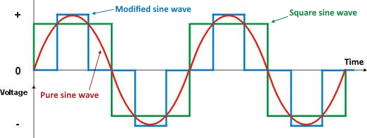
A power inverter converts direct current (DC) into household alternating current (AC). Until the past decade or so, the modified sine wave inverter was the most common (and simplest) type. The earliest version accomplished the conversion by adjusting the voltage straight up and down, which results in a square sine wave signal. Later version made the adjustments in smaller increments in an attempt to smooth out the curve. It works fine for powering anything that doesn't have delicate electronics like a computer, battery charger, or digital devices. Things like radios, brushed motors, old tube TVs and incandescent lights will run fine on modified sine wave. Some modern appliances might seem to work fine, but will consume much more power and run hotter than normal, which will decrease lifespan and increase the risk of an electrical fire. So a person has to take care with what they operate from a modified sine wave inverter. These inverters aren't suitable for general household use, in most cases.
The alternative to a modified sine wave inverter is a pure sine wave inverter. These are generally more expensive, but they produce a much smoother sine wave signal which can operate delicate electronics more efficiently (25-30%) and without risk of damaging them, as long as the inverter is sized properly, of course. Despite their price, pure sine wave inverters have become the more popular choice these days simply because they're the most versatile. |
|
Off Grid Vs Grid Tie Inverters
Whether you want a grid tied or off grid system will further determine what you need for a power inverter. Off grid power inverters are designed to convert DC power from a battery bank to AC power that will supply the home or business, and are generally rated for 12, 24, or 48 VDC input to 120 and/or 240 VAC output.
In a grid tied system, there's no need for charge controllers or batteries. As such, grid tie inverters connect directly to the main grid, and convert the DC power directly from a PV array or wind turbine to AC power that will help supply the grid and lower your energy use from it. Like MPPT controllers, grid tie inverters will accept a high input voltage (sometimes up to 500 VDC), and step it down (or up) to 120 V - 240 VAC to match the grid.
Some inverters are hybrids, meaning they can supply power to the grid as well as connect to a battery bank for back up power in case the grid goes down, effectively serving as an uninterrupted power supply (UPS). Others, called inverter/chargers, draw power from a battery bank for off grid power, but can connect to the grid (if available) to charge the battery bank in case the PV array or wind turbine goes down.
Sizing A Power Inverter
How big a power inverter needs to be will first depend on what type of inverter it is. If it's an off grid inverter, then its size will depend on the total instantaneous power it will be expected to provide. This can be determined by simply adding up the total power rating of all appliances and electrical devices that it will power. For example, if you're considering a small backup system for grid outages, and want to power a 400 W refrigerator, a 500 W deep freezer, a 500 W hot plate, and 100 W of LED lights, then the minimum continuous power rating for the inverter will be 1500 watts. This is how much power can be drawn from it continuously.
Power inverters are also rated for surge power. When a device with an electric motor turns on, the initial power draw can be twice as much as what it's rated for or more. This surge only lasts for a split second and inverters are typically designed to only handle a surge for a few seconds, but it does need to be accounted for to protect equipment. For the example above, a 1500 W continuous/3000 W peak power rating would suffice.
If your sizing a grid tie inverter, then its total power rating will depend on how much power will be feeding into it from your PV panels or wind turbine. As in the above example, you'll need to be mindful of surges. With PV, simply add 25% to the total array power and this will be the minimum power rating for your grid tie inverter. For example a 1000 W array would need 1000 x 1.25 = 1250 W power inverter. When it comes to a wind turbine, refer to the manufacturer's peak power rating at braking speed (when the turbine's automatic braking feature activates in high winds, in most cases it's a furling tail mechanism). The peak power rating will be the minimum power rating of your grid tie inverter.
The next thing to consider is voltage. For an off grid inverter, you'll need to know the voltage of your battery bank, and the out AC voltage that you need to supply your electronics. As mentioned previously, off grid inverters are generally rated for 12, 24, or 48 VDC input from the batteries, converting to 120 and/or 240 VAC split phase output.
For a grid tie inverter, you'll need to know the total peak input voltage from your PV array or wind turbine +25% to compensate for surges, as well as the AC grid voltage that the inverter needs to convert it to.


