
Solar HVAC 1: Molecular Sieve Rotor Testing
Updated July 26, 2016: Double Rotor 'Matrix' (scroll to bottom)
|
|
Share with your friends:
|
The testing and information presented below was done to approximate the effectiveness of using recycled molecular sieve desiccant beads to dehumidify an air stream produced in a small co-generative solar HVAC system.
Introduction/Hypothesis:
A desiccant is a material with a highly porous surface that adsorbs moisture from the air (unlike a'b'sorption, adsorption is when moisture collects on a material's surface only). The pores are microscopic, only nanometers in width - the more pores there are, the more surface area there is and the more moisture that can be adsorbed. Desiccants are commonly used in applications like packaging to keep products/goods dry during shipment and storage, and in window and door panes to prevent condensation build up on the glass. Desiccant rotors or 'desiccant wheels' are typically used for dehumidifying air in a living or work space and are manufactured in a variety of sizes, but are costly. A variety of materials can be used as a desiccant, but the most common are activated clay and molecular sieve (windows & doors), silica gel (goods/produce packaging), and activated alumina (used in some high performance desiccant rotors).
A desiccant is a material with a highly porous surface that adsorbs moisture from the air (unlike a'b'sorption, adsorption is when moisture collects on a material's surface only). The pores are microscopic, only nanometers in width - the more pores there are, the more surface area there is and the more moisture that can be adsorbed. Desiccants are commonly used in applications like packaging to keep products/goods dry during shipment and storage, and in window and door panes to prevent condensation build up on the glass. Desiccant rotors or 'desiccant wheels' are typically used for dehumidifying air in a living or work space and are manufactured in a variety of sizes, but are costly. A variety of materials can be used as a desiccant, but the most common are activated clay and molecular sieve (windows & doors), silica gel (goods/produce packaging), and activated alumina (used in some high performance desiccant rotors).
|
Compared to conventional air conditioners, evaporative coolers - aka, swamp coolers - use much less electricity because they don't have to run a compressor to pressurise and pump a refrigerant; with the exception of a blower fan and small water pump, swamp coolers rely on the principle of evaporative cooling, whereby a stream of hot dry air can be cooled as it absorbs moisture from a cool water source. A simple example of the evaporative cooling process is the way our bodies sweat to keep us cool; our skin secrets fluids when we're hot so that when it evaporates into the air it will take some body heat from us with it. Unfortunately, the more humid the air is, the less moisture it will absorb so swamp coolers tend not to work well in climates where the average daytime relative humidity is above 50%, which normally limits their use to the south west United States.
|
|
The ultimate purpose of this research is to develop an affordable desiccant rotor with recyclable materials that can be incorporated with solar air heating and evaporative cooling units in a prototype co-generative HVAC system to investigate it's potential in lowering both cooling costs during the summer in humid north eastern regions, as well as lower heating costs during the winter. Specifically, the rotor developed from this research will be used to adsorb moisture from fresh outdoor air to lower it's humidity before it enters the swamp cooler to help it cool more effectively before it's blown into the living space. A solar air heater will remove warm air from the ceiling to help cool and equalise the pressure in the living space. The warm air is then heated as it passes through the solar heater and this 'waste heat' will then be used to regenerate the desiccant rotor (remove moisture from the desiccant) as it slowly rotates between (absorbing moisture from) the humid incoming outdoor air and the exhausted hot air in a sealed double chambered housing.
The average daytime relative humidity in most of Canada and the north eastern United States is between 60-65%. If the incoming air stream passing through the desiccant rotor can be dehumidified by 20% or more, then it should be dry enough to be cooled efficiently via an evaporative cooler in these humid regions.
The average daytime relative humidity in most of Canada and the north eastern United States is between 60-65%. If the incoming air stream passing through the desiccant rotor can be dehumidified by 20% or more, then it should be dry enough to be cooled efficiently via an evaporative cooler in these humid regions.
|
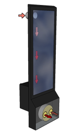
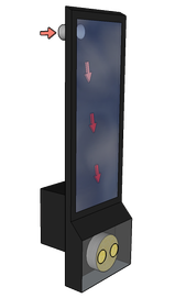
Summer Cooling/Dehumidify Mode
Warm indoor air is removed from the ceiling via the solar heater and is used to dry the desiccant wheel. Fresh outdoor air is pulled through the desiccant wheel to be dried before entering the evaporative cooler |
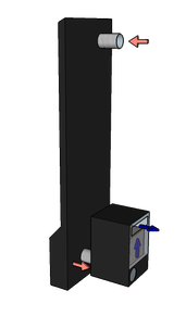
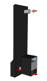
Winter Heating Mode
Indoor air is pulled from the ceiling and through the solar heater to be heated before being exhausted back into the living space at floor level (where it's the coldest) |
|
|
|
|
|
Methods:
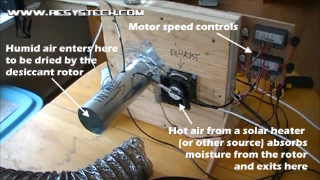
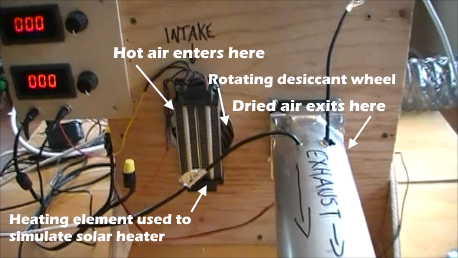
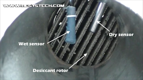
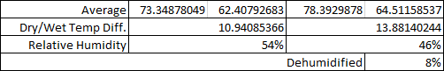
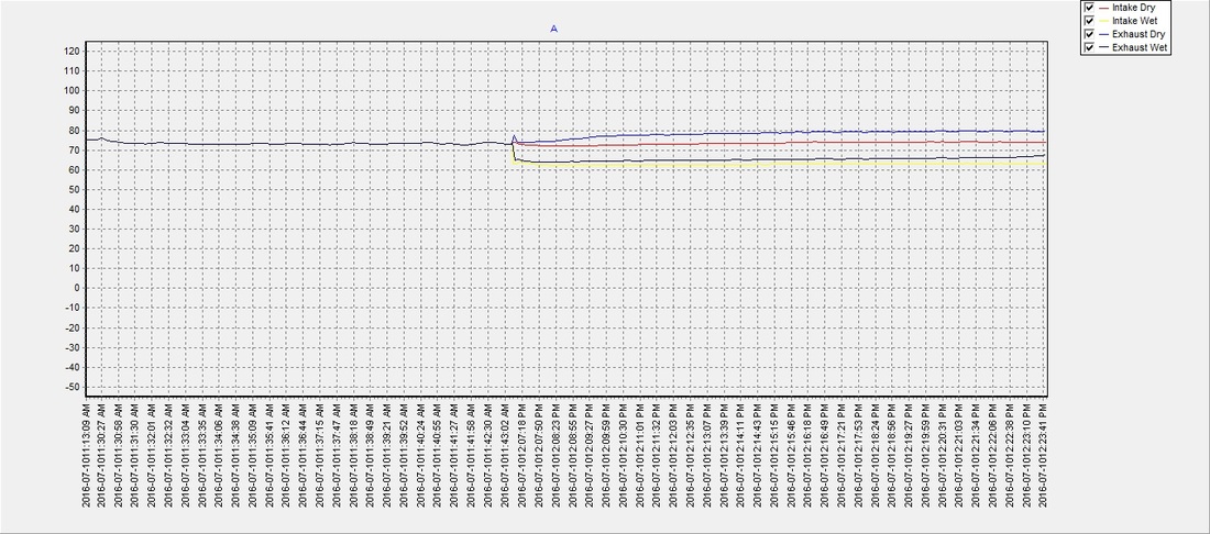
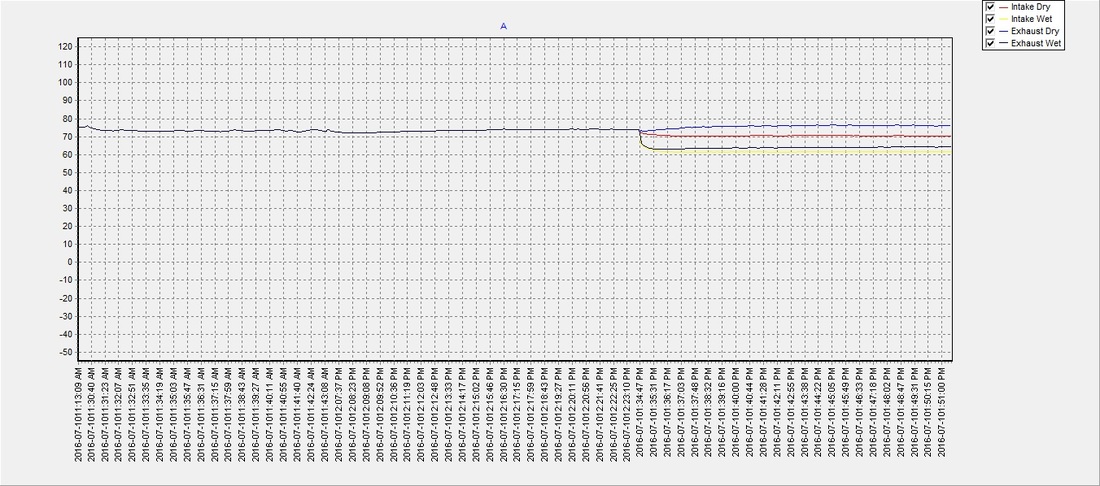
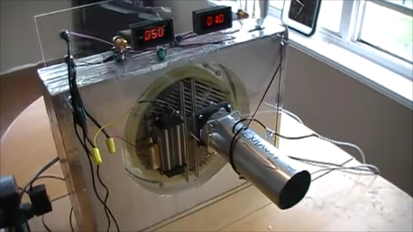
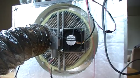
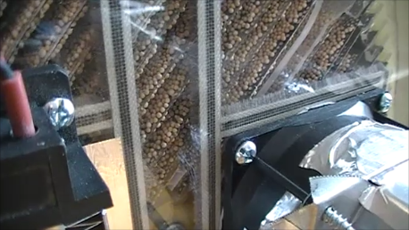
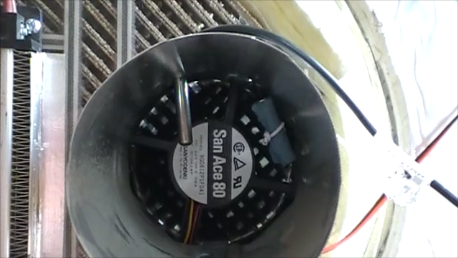
The desiccant rotor measures 11 1/2" in diameter and is 2" deep in total; for the sake of maintaining a low profile in the solar heater, I'm starting with a shallow rotor - if it's determined that more dehumidification is needed then a deeper rotor with more desiccant can be made accordingly. The rotor 'rings' were cut from 3/4" birch plywood as can be seen in the video to the right, and saw kerfs were made with a jigsaw and spaced ~5/16" apart to hold the desiccant 'wafers'. The wafers were constructed from 2" wide strips of 0.023" thick aluminium flat stock. The desiccant was adhered to the aluminium via a thin layer of a two part, non-shrink, high temperature epoxy that contained no VOC's. Once cured, the wafers were cut to length and friction fit into the saw kerfs in the rotor rings. The rotor was then 'quartered' by placing narrow strips of wood in the centre of the rotor, between the wafer laminations; this will help keep the two air streams from mixing within the rotor. A simple housing was constructed from 3/8" fir plywood and a couple of layers of 1" polyisocyanurate foam board (for depth). The finished desiccant rotor was fitted to a 12VDC motor (speed adjusted to 2 rpm) and placed in the housing; a ~1/8" gap was maintained around the perimeter of the rotor for clearance and a strip of felt was used for a seal that provided minimal friction on the rotor. Two 12VDC, 38mm x 80mm axial fans were used to produce separate 35 cfm air flows (velocity dictated by the solar collector size/design) through the dehumidification and regeneration chambers. A 120VAC/500W PTC heating element was fastened to the intake port of the regeneration chamber to simulate the hot air flow from a solar air heater. The relative humidity of the air flow before and after entering the dehumidification chamber will be approximated using the wet and dry thermometer method. This involves using a pair of thermometers at each port to measure temperature differences, however one thermometer in each pair will have a wet wick wrapped around it so that as the air passes by it will cause the water to evaporate, and the wet thermometer will be slightly cooler than the other as a result (another application of the evaporative cooling effect mentioned previously), which tells us something about the moisture content in the air - the greater the difference in temperature between the dry thermometer and the wet thermometer, the lower the humidity is. The relative humidity can then be determined by inputting the temperature difference (among other factors) into a complex equation, or an online chart/calculator can be used. The data from this test will be collected via four NTC sensors, and logged/graphed using PC software and Microsoft Excel. |
Making The Rotor
Performance Test Video
|
|
|
|
Results:
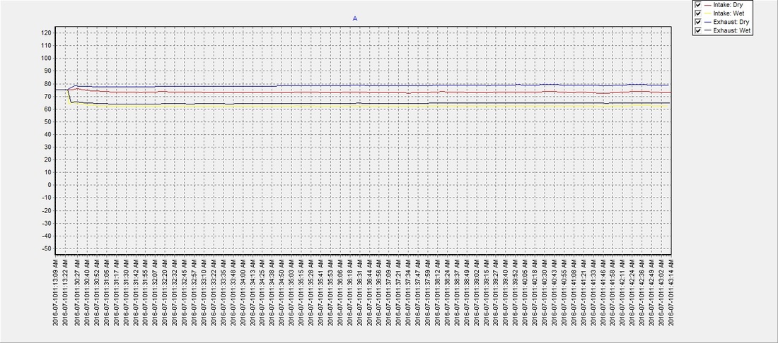
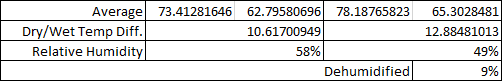
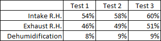
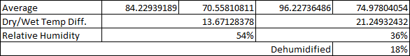
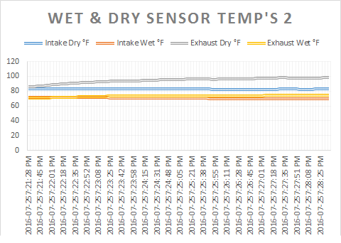
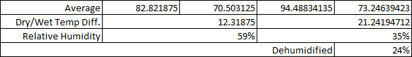
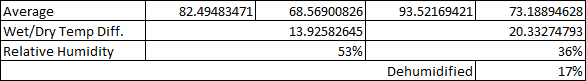
All functions operated well. However, the air flow was only dehumidified between 8%-9% in each test - which isn't too bad considering the rotor is only 2" deep. There was also a small transfer of heat from the regeneration chamber to the dehumidification chamber that was stored by the desiccant beads after they were dried, and subsequently the dehumidified air temperature was raised a few degrees more than the intake temperature - more airflow through the regeneration chamber may help keep this transfer to a minimum and help the swamp cooler work more efficiently, which will be investigated in the next test.
The next step in trying to achieve the 20% dehumidification goal before moving on with the prototype build will be to make another, deeper desiccant rotor that contains more desiccant for more surface area contact with the airflow and (hopefully) a higher adsorption rate. Silica gel wafers will also be tested in the future and compared with the results from this molecular sieve research.
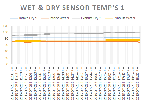
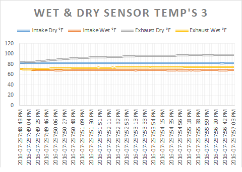
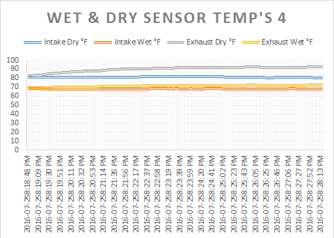
Wet & Dry Sensor Temperature Data
|
Test 1
|
Test 2
|
Test 3
| ||||||
Relative Humidity Results
|
07/26/16 Update: Double Rotor 'Matrix' Testing
As mentioned previously, to reach the 20% dehumidification goal I made a new rotor with twice as much surface area and desiccant as the first. The new rotor is actually a combination of two rotors configured at right angles to each other to form a 'matrix' so that they split up the air stream better as it passes through and transfers moisture to the beads. The only other difference between the construction of the new rotor and the old is the new one has an acrylic frame to make it lighter (machined from aluminium would be ideal for real world applications, but the acrylic will do fine for testing purposes). Acrylic also replaced the 3/8" plywood used in the housing for a better view of the rotor when operating. The test methods remained exactly the same as the previous test. |
|
|
|
|
|
|
Results:
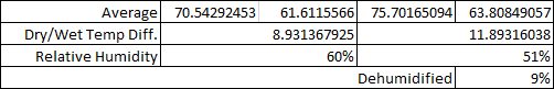
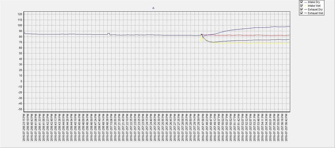
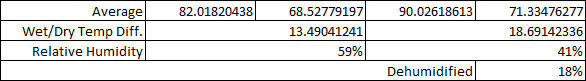
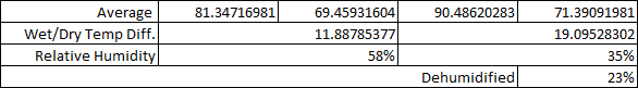
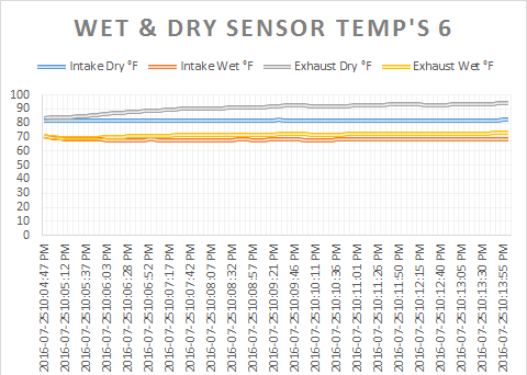
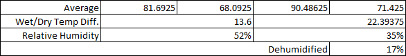
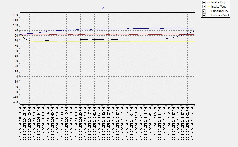
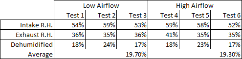
The new rotor performed as expected by dehumidifying the air stream by ~19% on average. There was still a considerable heat transfer from the regeneration chamber to the dehumidification chamber and the dry air reached up to 98°F (37°C) as a result. Another set of tests were later done with a faster airflow through the regeneration chamber (90 cfm) to help distribute the heat from the PTC element to more air and lower the amount absorbed by the desiccant beads, which resulted in a lower heat transfer between the two chambers and subsequently lowered the dry air temperature exhausted from the dehumidification chamber to approximately 90°F (32°C). The extra airflow to lower the temperature came at a cost of ~10 watts/h (electrical power to fan), but this will be beneficial later when it comes to lowering the work load on the (soon to be built) evaporative cooler and helping it operate more efficiently. Data from these latest tests can be viewed below: |
|
Wet & Dry Sensor Temperature Data (w/ low airflow)
|
Test 1
|
Test 2
|
Test 3
| ||||||
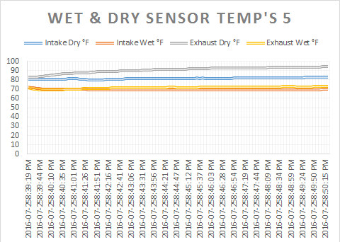
Wet & Dry Sensor Temperature Data (w/ high airflow)
|
Test 4
|
Test 5
|
Test 6
| ||||||
Relative Humidity Results
|
|
|